Note: Descriptions are shown in the official language in which they were submitted.
CA 02484196 2004-10-28
WO 03/095349 PCT/US03/14347
1
ADJUSTABLE, SELF-CORRECTING WEB
SUBSTRATE FOLDING SYSTEM
FIELD OF THE INVENTION
The present invention relates to an adjustable, self-correcting web substrate
folding system that can sense a physical characteristic of a moving web
substrate that is
undergoing folding and adjust the fold angle geometry to provide the correct
tension.
BACKGROUND OF THE INVENTION
As is known in the art, folding a web substrate generally involves the
manipulation of the web substrate according to principles of equal path
length. Simply
stated, the machine direction (MD) folding of a web substrate for equal path
lengths
requires each cross-machine direction (CD) point of the web substrate to
travel an equal
geometric distance (equal path geometry) across a folding surface. Thus, each
portion of
the web substrate is provided with equal tension and proper web tracking. As
is known in
the art, equal path geometry provides the best processing for a uniform web.
Tearing or the reduction of baggy edges during a folding operation generally
requires stopping the folding line to enable personnel to effect manual
changes to the
equal path geometry. Stoppages result in lost production time and increased
production
costs. Additionally, manual changes are generally inaccurate and may require
additional
production stoppage in order to affect further serial, or incremental, equal,
or unequal,
path geometric changes. Further, a line stoppage requires an entire web
substrate
processing line be shut down at the parent roll stage. Such a shut down can
result in
capital losses, due to the inability to produce any intermediate or end
products during the
period of time the processing line is down. I
Equipment for completing folds in high-speed web processes is well known in
the
art. Folding formers, folding plates, and "V"-folders, and the like, are
machined detours
and polished sheet metal elements over which a web substrate is guided. A
typical "V"-
folder would consist of a generally triangular structure that would include a
folding plate
surface that initially receives the moving web substrate. A folding plate is a
generally flat
CA 02484196 2004-10-28
WO 03/095349 PCT/US03/14347
2
surface with a pair of spaced-apart converging edges. A folding plate
typically has a
terminal nose surface contiguous to the transition nose surface and merges
smoothly
therewith forming an oblique angle with it. The terminal nose portion
terminates in a
point that defines the location of the fold.
Typically, and as is generally known to one of skill in the art, a folding
detour
generally has a first, or input, angle, a, a second, or side, angle, 0, and a
third, or resultant,
angle, y, and will generally fold a web substrate along the longitudinal axis
of the web
substrate. During folding, failure to maintain a proper relationship between
the input
angle, a, side angle, 0, and/or resultant angle, y, can cause folding
equipment stoppages.
This is because one edge of the web substrate is longer than the other, and
the fold
geometry must be adjusted accordingly.
The tendency for a web substrate passing over folding structures to not run or
lay
flat and straight is generally due to a folding phenomenon hereinafter
referred to as a
"baggy edge." A baggy edge can result when one edge of a roll of web stock is
physically
longer than the other edge. This physically longer, or curved, edge can be
demonstrated
by rolling out an amount of web material and observing a general "C"-shape, or
curve, in
the rolled-out portion.
A baggy edge could exist because of either a deviation of strain, stress, or
flatness
in the web substrate. Additionally, cambered web substrates, common on narrow
webs
that have been cut from a wide parent roll of web substrate, can also have
sufficient
deviation to produce a baggy edge in a web substrate folding operation.
A baggy edge, or baggy web substrate, can cause wrinkling during a folding
operation due to an insufficient machine direction (1VID) tension. This baggy
edge may
result in a bubble, leaving wrinkles in the folded substrate and causing
potentially
significant deviations in the ability to laminate or coat, or the lack of
ability to produce
flat material bonding, or provides difficulties in passing a moving web
substrate over flat
rollers. This off-quality product requires operator intervention to correct
and typically
requires the complete shut down of a folding operation and an ensuing loss of
production
efficiency.
,
CA 02484196 2004-10-28
WO 03/095349 PCT/US03/14347
3
A typical folder is shown in Dutro, U.S. Patent No. 3,111,310. Dutro discloses
a
complex series of folding plates for making a fold in a web or ribbon of
paper. Curved
flanges bound the converging edges of the fold plate and transition nose
surfaces. A flue
is formed integrally within the flanges. Dutro uses conventional folding plate
technology
and does not allow for in situ adjustment of the folding plate to reduce a
baggy edge in a
passing web substrate.
Similarly, other patents show the use of folding plates in various
configurations.
Exemplary patents include: Great Britain Patent Nos. GB 946,816, GB 1,413,124,
and GB
862,296, and U.S. Patent Nos. 4, 131,271; 4,321,051; and 5,779,616. However,
none
teach or disclose a device that provides continuously adjustable, self-
correcting tension on
a passing web substrate undergoing folding.
However, because nips are widely used in the industry for laminating,
printing,
winding, coating and calendaring, it is essential to minimize bagginess, or
over-tension, in
a moving web substrate. Roisum, Web Bagginess: Making, Measurement and
Mitigation
Thereof, suggests that line tension can be increased in the machine-direction
to remove
contraction from the shorter edge of a web to reduce bagginess. Thus, only a
machine
direction tension is applied to the shorter edge of a web substrate in an
attempt to lengthen
the shorter edge. However, Roisum also suggests that this method has several
limitations
and can be difficult to achieve. Most significantly, it is suggested that this
technique does
not work well with stiff webs that may break before flattening. Additionally,
it is
suggested that this process may not provide uniform results as small puckers
may still
occur in the web substrate, resulting in an imperfect edge. Further, the
application of
additional machine direction tension becomes difficult in application when
several web
substrates are combined in-line. If one web substrate exhibits properties of
non-
uniformity, in-line tension must be applied to all webs being combined. To
apply tension
to only one web of a plurality of combined webs can cause ruffling in the
final product, a
potentially undesirable end result.
Accordingly, it would be desirable to provide an adjustable, self- correcting
web
substrate folding system for in situ folding of a web substrate that can
provide continuous
CA 02484196 2005-08-18
4
adjustments to the web substrate folding system prior to web substrate contact
with a
folding detour. This can minimize web substrate bagginess during folding and
yet still
provide a high quality finished product.
SUMMARY OF THE INVENTION
The present invention is an adjustable web folding system for folding a web
substrate having a machine direction and a cross-machine direction. The
adjustable web
folding system comprises an adjustable folding detour disposed in a position
and having a
longitudinal axis coincident with the machine direction of the web substrate;
at least one
sensor for measuring a characteristic of the web substrate prior to said web
substrate
contacting the adjustable folding detour; and, wherein the position of the
adjustable
folding detour is adjustable in response to the value of the characteristic of
the web
substrate prior to the web substrate contacting the adjustable folding detour.
The present invention is also an equal path folder comprising a folding detour
having a longitudinal axis for producing a fold in a web substrate having a
longitudinal
axis, a machine direction, and a cross-machine direction, with the web
substrate moving
in the machine direction. The folding detour has a folding angle disposed
thereon; a first
force measuring sensor for measuring a first force in the web substrate prior
to the web
contacting the folding board; a second force measuring sensor for measuring a
second
force in the web substrate prior to the web contacting the folding board. The
first force
and the second force are compared and produce a resultant force; and, the
folding angle is
adjustable in relation to the value of the resultant force prior to the web
contacting the
folding board.
All patent and non-patent references cited are herein incorporated by
reference.
BRIEF DESCRIPTION OF THE DRAWINGS
FIG. 1 is a perspective view of a preferred embodiment of an adjustable, self-
correcting, web substrate folding system, with an exemplary web substrate
being folded,
in accordance with the present invention;
FIG. 2 is an elevational view of an adjustable, self-correcting, web
substrate,
folding detour;
CA 02484196 2004-10-28
WO 03/095349 PCT/US03/14347
FIG. 3 is a bottom view of an adjustable, self-correcting, web substrate,
folding
detour;
FIG. 4 is a view of an exemplary single-sensor for use with an adjustable,
self-
correcting, web substrate folding system; and,
FIG. 4A is a cross sectional view of the exemplary single sensor of FIG. 4
taken
along the line 4a-4a.
DETAILED DESCRIPTION OF THE INVENTION
The present invention is an adjustable, self-correcting web substrate folding
system. The adjustable, self-correcting web substrate folding system is
generally capable
of measuring a differential, or comparative web characteristic, such as a
resultant tension
force, and adjusting the fold angle of the web folding system in response to
the value of
the measured differential web characteristic. As used herein, "machine
direction" refers
to the general direction of travel of a web substrate along the longitudinal
axis of the web
substrate. As used herein, "cross-machine direction" generally refers to the
axis that is
orthogonal to the 1VID and coplanar with the web substrate. The "z-direction"
generally
refers to the axis that is orthogonal to both the machine- and cross machine
directions.
Further, it is generally known that the first, or input, angle, a, generally
refers to a fold in
the z-direction of a web substrate. It is also generally known that the third,
or resultant,
angle, y, generally refers to a fold in the cross-machine direction of a web
substrate. It is
further generally known that the second, or side, angle, 0, generally refers
to a con7pound
fold between the input angle, a, and the resultant angle, y, and generally
comprises a fold
in both the z- and cross-machine directions. The transition point is generally
known as
the point of intersection for angles a, 0, and y.
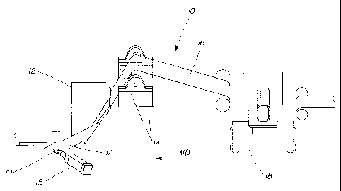
As shown in FIG. 1, the adjustable, self-correcting, web folding system is
represented by the numeral 10. The adjustable, self-correcting, web folding
system 10
generally comprises an adjustable folding detour 12 and at least one sensor
(sensor) 14 for
measuring a characteristic of a web substrate 16 traveling in the machine
direction (MD).
The adjustable, self-correcting, web folding system 10 can also comprise
optional guide
18, and an optional at least one sensor 19 positioned downstream, in the MD,
from folding
CA 02484196 2004-10-28
WO 03/095349 PCT/US03/14347
__
6
detour 12 or in the resultant angle, y, of folding detour 12. Within the scope
of the present
invention, sensor 14 can comprise any number of sensors. However, it is
preferred that
sensor 14 be capable of producing a measurement that is representative of some
characteristic of the web substrate 16 that may ultimately bear a relationship
to the folding
of web substrate 16. That is, the characteristic of the web substrate 16
chosen should be
indicative of a characteristic of web substrate 16 that can vary from one
substrate to
another, or within the same substrate, in either the machine- or cross-machine
direction, or
any combination thereof.
As would be known to one of skill in the art, non-limiting and exemplary,
folding
detours 12 can comprise a single, or a cascaded series of folding boards,
folding plows,
folding rails, goat horns, ram horns, turn bars, folding formers, folding
fingers, and
combinations thereof. As would also be known to one of skill in the art, any
combination
of folding devices can be combined to form any number of folds as required by
a folding
operation. For example, two folding rails, each having a folding edge disposed
thereon,
can be combined to make a "V"-folder. Likewise, as would be known to one of
skill in
the art, a series of "V"-folders can be combined to produce a "C"-folder.
Similarly, as
would be known to one of skill in the art, several folding plows positioned in
series in the
machine direction can complete a series of two tucks in web substrate 16 to
produce a
"Z"-folder. In any regard, as web substrate 16 progresses through each portion
of folding
detour 12, it is desirable that web substrate 16 maintain equal path folding
geometry.
Illustrative depictions of exemplary, but non-limiting, adjustable, self-
correcting, web
folding systems are described in Examples 11-13 iizfra.
Exemplary, but non-limiting, web characteristics that can be measured include
tension, opacity, caliper, shear, basis weight, denier, elongation, air flow,
stress, strain,
modulus of elasticity, coefficient of friction, surface finish RMS, yield
strength, color,
stiffness, bending modulus, temperature, dielectric constant, static electric
charge,
physical composition, and combinations thereof. Exemplary, but non-limiting,
sensors 14
for measuring web characteristics include a beam and fulcrum, strain gauges,
optical
sensors, photoelectric sensors, electrical sensors, electro-mechanical
sensors, opacity
CA 02484196 2004-10-28
WO 03/095349 PCT/US03/14347
7
sensors, ultrasonic sensors, inductive sensors, variable reluctance sensors,
magneto-
strictive sensors, laser sensors, nuclear sensors, and combinations thereof.
In a preferred
embodiment, sensor 14 includes a pair of load cells sensitive to the tension
present in
cross machine direction edges of moving web substrate 16. Illustrative
depictions of
exemplary, but non-limiting, sensor 14 arrangements and techniques are
detailed in
Examples 1-10 iyafra.
As shown in FIGS. 2 and 3, folding detour 12 can be moveable, adjustable,
and/or
provided with at least one surface that is moveable and/or adjustable, or
provided with an
edge, or break, 17 with which it is possible to change at least one angle (a,
(3, or y) of the
overall equal path geometric fold provided by folding detour 12. Thus, the
edge can be
disposed at and angle relative to the longitudinal axis, thus defining an
angle
therebetween. In other words, moveable break 17 could be associated with a
change in
any one of angles a, 0, or y, or can be arranged to adjust any combination of
angles a, P,
or y, and thus, the included angle. In a preferred embodiment, folding detour
12, or
moveable break 17, can be adjusted in response to the value of at least one
differential
web characteristic present between cross machine direction edges of web
substrate 16 as
measured by sensor 14. The value of at least one differential web
characteristic can be the
magnitude of the differential web characteristic. For example, if the
resultant of the
sensor 14 measurement determines that one edge of web substrate 16 has a
higher tension
(i.e., has a shorter overall length) than the other edge (i.e., a
differential, or resultant,
tension is present), then input angle a, side angle (3, and/or resultant angle
y of folding
detour 12 could adjust away from the higher tension side of web substrate 16
(i.e., angle a
becomes smaller) until the value of the measured differential web
characteristic
approaches zero. Ideally, a web substrate 16 experiencing no differential web
characteristic as measured by sensor 14, and adjusted by folding detour 12,
produces a
fold exhibiting no bagginess. It is believed that actuator 15 could be coupled
to moveable
break 17, or folding detour 12, to provide movement of moveable break 17,
and/or folding
detour 12, upon detection of a differential web characteristic by sensor 14.
As shown in FIGS. 3 and 3A, an exemplary, and non-limiting, sensor 14 capable
CA 02484196 2004-10-28
WO 03/095349 PCT/US03/14347
8
of measuring a differential web characteristic of web substrate 16, for
example a
differential tension, could be a mechanical beam pivotable about a fulcrum. As
the web
substrate 16 passes over the beam, the beam could balance about the fulcrum in
relation to
the differential tension present in the cross machine direction of web
substrate 16. As the
cross machine direction web tension of moving web substrate 16 increases, or
decreases,
on one edge due to inconsistent web substrate 16 edge lengths, the beam could
pivot about
the fulcrum, thus providing a measurement of the differential tension between
both edges
of the web substrate 16. The differential tension measured could then result
in an
adjustment of moveable break 17 or folding detour 12 in any one of the angles
(a, 0,
and/or y) present in folding detour 12 in response to the magnitude of the
upstream
measurement.
As shown in FIG. 2, an exemplary, and non-limiting, sensor 14, capable of
measuring a differential web characteristic, would provide two sensors capable
of
measurement of a differential web characteristic of web substrate 16. It is
preferred that
both sensors 14 be equally spaced from the longitudinal axis of web substrate
16,
however, one of skill in the art would be able to place two sensors 14 at any
two points
bounding web substrate 16 in the machine direction, cross machine direction,
or any
combination thereof, and still be able to provide a measurement of a
differential web
characteristic of web substrate 16. For example, the differential tension of
web substrate
16 present between the sensors 14 could result in an adjustment in any one of
the angles
(a, 0, and/or y) present in folding detour 12 in relation to the magnitude of
the upstream
measurement.
An exemplary, and non-limiting, sensor 14 system comprising multiple sensors
14
capable of measuring a differential web characteristic would provide a
plurality of sensors
14 capable of measurement of the web substrate 16 differential web
characteristic in the
general cross machine direction of web substrate 16. As would be known to one
of skill
in the art, generally arranging a plurality of sensors 14 in the cross machine
direction of a
web substrate 16 could supply the additional benefit of providing a more
accurate
depiction of any web deformities, or inconsistencies, in terms of a deformity
profile of a
CA 02484196 2004-10-28
WO 03/095349 PCT/US03/14347
9
web substrate 16. Additionally, the deformity profile could provide the
ability to track
single or multiple web substrate characteristics over time in order to develop
angle
adjustment profiles for various web substrates. Based upon the profile
provided by a
plurality of sensors 14, it could be possible to provide for an even more
consistent fold
and further reduce web substrate 16 bagginess. Additionally, a plurality of
sensors 14
could be advantageous in the ability to accommodate virtually an infinite
arrangement of
folds in terms of the number of folds undergone by web substrate 16 and amount
of fold-
over undergone by web substrate 16 as web substrate 16 progresses though a
series of
folding detours 12.
Referring again to FIG. 1, in any regard, it is preferred that sensor 14 be
capable of
producing at least one quantifiable measurement of a characteristic of web
substrate 16.
Thus, it would be known to one of skill in the art that the quantifiable
measurement made
by one sensor 14 could be compared with the quantifiable measurement made by
another
sensor 14. The value of the comparison of quantifiable measurements made by at
least
one sensor can be used so that folding detour 12 can be adjusted, as described
supra, to
maintain uniform tension in the web substrate 16 prior to contact with folding
detour 12.
In essence, this would be known to one of skill in the art as a feedback loop,
or a form of
error correction. Maintenance of constant web tension throughout web substrate
16 can
reduce the bagginess in web substrate 16 after contact with folding detour 12.
Additionally, one of skill in the art would realize that it is possible to
place at least one
sensor 19 downstream in the machine direction from folding detour 12 to
provide
additional measurements of web substrate 16. Additionally, sensor 19 can be
placed in
the resultant angle, y, of folding detour 12, however, one of slcill in the
art could place
sensor 19 in any of the included angles a, (3, and/or y, or downstream, in the
machine
direction, from the resultant angle, y, of folding detour 12. Such additional
measurements
of web substrate 16 can provide further feedback of web characteristics to
enable folding
detour 12 to be incrementally adjusted to further reduce web substrate 16
bagginess.
Again referring to FIG. 1, continuously adjustable web folding system 10 can
be
provided with guide 18. The central portion of guide 18 could be placed prior
to sensor
CA 02484196 2004-10-28
WO 03/095349 PCT/US03/14347
14 to provide for tracking of the longitudinal axis of web substrate 16 in the
machine
direction. That is, the longitudinal axis of web substrate 16 would preferably
align with
the MD axis of sensor 14 and/or folding detour 12. Overlapping the
longitudinal axis of
web substrate 16 with the MD axis of sensor 14 and folding detour 12 could
also facilitate
the removal of any bagginess in the web by ensuring that any folds experienced
by web
substrate 16 are produced around the MD axis of folding detour 12.
It is also believed that one skilled in the art could fold a web substrate
using an
adjustable, self-correcting web substrate folding system by supplying a web
substrate and
an adjustable folding detour. The skilled artisan could then measure a
characteristic of the
web substrate prior to the web substrate contacting the adjustable folding
detour. The
adjustable folding detour could then be adjusted, as described supra, in
response to the
value of the measured characteristic of the web substrate.
Examples
The following examples describe non-limiting, exemplary web substrate 16
baggy,
or tight, edge detection methods consistent with the scope and spirit of the
present
invention. All detection methods could provide a control signal that activates
the
adjustable, self-correcting, web substrate folding system (system) by
increasing the
tension on the loose edge, or decreasing the tension of a taut edge of a
moving web
substrate 16.
Example 1- Strain Gauge (Load cells):
An electrical voltage is passed through a calibrated wire or semi conductor
matrix
bonded to a flexural member. A force applied to the flexural member causes
flexion in
the matrix thereby varying the resistance of the matrix. The change of voltage
is
calibrated to known forces for a given flexion range.
Employing two strain gauges on opposing ends of a connecting bar or idler can
facilitate monitoring of both edges of a web substrate. As a substrate passes
over a
connecting idler, the two edges of the web can be monitored to indicate if one
edge is
exerting less force on the respective strain gauge than the other.
It is believed that hydraulic load cells, pneumatic load cells, and
capacitance
CA 02484196 2004-10-28
WO 03/095349 PCT/US03/14347
11
pressure detectors (measurement of change in capacitance resulting from the
movement of
an elastic element) can be used in a similar fashion.
Example 2 - Fulcrum / Potentiometer
A simple fulcrum system can be fashioned, to position a potentiometer
(variable
resistor) in the center of a balanced bar or idler system. This pivoting
system becomes
unbalanced when the force exerted by one edge of a web substrate against the
fulcrum
member is greater than the force exerted by the other edge of the web
substrate against the
fulcrum member. This imbalance causes the fulcrum system to move in the
direction of
the greater force.
A radial potentiometer, connected to the fulcrum, adjusts the voltage of an
applied
control signal that activates the system. This method is also believed to be
applicable to
mechanical lever scales.
Example 3 - Photoelectric Sensing
An optical system can be designed to emit light through a polarizing filter.
As a
web substrate passes over the light source, the web substrate acts as a
reflective surface to
reflect at least a portion of the polarized light toward a detector. Two or
more
photoelectric sensors can be used provide comparative feedback.
When the web substrate is taut, maximum reflected signal is received. As the
web
substrate edge bagginess increases, the amount of reflected polarized light
decreases,
thereby activating the system.
Example 4 - Opacity Sensing
A through beam opacity frequency sensor can be used to sense the relative
tension
in a web substrate. Using ultra-low frequency (ULF), or back electro magnetic
force,
senses physical changes in the web substrate, activating the system.
Example 5 - Laser
A laser sensor projects a beam of visible or non-visible laser light onto the
web
substrate. A line scan camera views reflected light from the web substrate.
The light
travel distance is then computed from the image pixel data. Alternatively, a
laser sensor
can also be used with a triangulation method to calculate distance, as would
be known to
CA 02484196 2004-10-28
WO 03/095349 PCT/US03/14347
12
one of skill in the art. The presence of a baggy edge alters the distance the
reflected light
travels indicating that a correction to the folding detour is necessary,
thereby activating
the system.
Example 6 - Ultrasonic
Ultrasonic technology can provide a non-contact sensor to detect distance.
Typically, three main variations of ultrasonic sensing modes exist: proximity,
retro-
reflective, and thru-beam. These sensors provide continuous monitoring of the
distance to
the edge of a web substrate, causing the system to adjust web substrate
tension, as
necessary.
Example 7 - Nuclear Radiation
Gamma rays are directed through a section' of a moving web substrate, for
example, the edges. The amount of non-absorbed radiation passing through the
web
substrate is generally dependent upon the physical characteristics of the web
substrate. A
radiation sensor converts this non-absorbed radiation into an electrical
signal that bears a
known relationship to the amount of web substrate material and the resulting
force
applied thereon, activating the system, as necessary.
Example 8 - Inductive SensingTechnique
Inductive weight and/or force sensors utilize the change in inductance of a
solenoid coil with changing position of an iron core. In a first embodiment,
two coils are
present with a common iron core. The system inductance is monitored in both
coils as the
web substrate physically moves the iron core more toward one coil than the
other.
Alternatively, a third coil can be physically located between the two
previously
described coils, as known to one skilled in the art of inductive sensors. The
overall
system inductance is monitored and appropriate folding detour corrections made
as
necessary.
Example 9 - Variable Reluctance Sensing Technique
The inductance of one or more coils is changed by altering the reluctance of a
small air gap. For example, solenoid coils are mounted on a structure of
ferromagnetic
material. A "U"-shaped armature is used to complete the magnetic circuit
through air
CA 02484196 2004-10-28
WO 03/095349 PCT/US03/14347
13
gaps. As a web substrate passes between the solenoid coils, a Wheatstone
bridge
develops a voltage proportional to the translation of the coil assembly. This
voltage then
activates the system, as needed.
Example 10 - Magneto-strictive Sensing Technique
Based on the Villari effect, this sensing technique utilizes the change in
permeability of ferromagnetic materials with applied stress. For example, a
stack of
laminations forms a load-bearing column. Primary and secondary transformer
windings
are wound on the column through holes oriented in a particular arrangement.
The primary
windings are excited with an AC voltage and the secondary windings provide the
output
signal voltage.
When the column is loaded, the induced stresses cause the peirneability of the
column to be non-uniform, resulting in corresponding distortions in the flux
pattern
within the magnetic material. Magnetic coupling now exists between the two
coils and a
voltage is induced into the signal coil as a web substrate passes between,
providing an
output signal proportional to the applied load, activating the system.
The following numbered examples describe non-limiting exemplary continuously
adjustable, self-correcting web folding systems consistent with the scope and
spirit of the
present invention. However, it should be realized that the present invention
is applicable
to folders that provide adjustment in discrete increments and/or only a single
time.
Example 11 - "V"-folder
A "V"-fold generally comprises a folding system consisting of two folding
rails
placed at a pre-determined inclination. One of the two folding rails is
constructed so that
the terminal end is pivotable, thereby allowing expansion of the "V" on one
side. The
pivotable folding rail is connected to an actuator, preferably a servomotor,
so that
adjustments can be made by a closed loop feedback from web-edge sensors as
discussed
supra. The sensors, upon indication of a differential web-edge tension, send a
signal to
the controller energizing the actuator. The actuator pivots, or increases the
included angle
of the "V" configuration, thereby increasing tension on the loose edge.
Conversely, when
an edge sensor indicates excess tightness in the web substrate, the sensor
signals a
CA 02484196 2004-10-28
WO 03/095349 PCT/US03/14347
14
stoppage to the angle adjustment or even a retraction of the included angle to
produce web
substrate edge equilibrium.
If both web substrate edge sensors are above, or below, a threshold level,
another
activator can be activated that decreases, or increases, folding detour
inclination. An
increase in folding detour inclination simultaneously tightens both web
substrate edges
until a threshold force and/or tension is met.
Example 12 - "C"-folder
A "C"-fold equal path folding system, as would be known to one of skill in the
art,
generally comprises an inlet elevation angle, a, a side angle, (3, and a
resultant, exit angle,
y, as discussed supra. When a web substrate has a baggy edge, a differential
edge tension
is generally present. When at least one sensor, described supra, senses a
differential edge
tension, the resultant angle, y, is adjusted accordingly. Continuous
adjustment can be
supplied by a closed loop feedback control between the edge sensor and the
pivotable
folding detour.
If the low-tension edge is sensed, a signal is sent to a motor controller,
energizing
a servomotor actuator, thereby changing the angle of the pivotable folding
detour. As the
edge tension increases, the sensor reduces signal to the controller, reducing
the angular
increase until equal web-edge tension equilibrium is achieved.
Example 13 - "Double-Break"-folder
A complex "double break"-folder, as would be known to one of skill in the art,
incorporates additional pivoting folding rails into a second brealc section.
In other words,
a "double break"-folder could be thought of as two individual folders series.
Without wishing to be bound by theory, it is believed that the side angle, (3,
of the
first folding section, should be made adjustable, rather than the exit or
resultant angle, y.
If the side angle, (3, is adjusted, then the path length of the entire folding
system could be
increased or decreased to optimize the first fold section. It is likely that
the second fold
section will also need a pivoting folding rail, in case the overall tension of
the second fold
section is not translated back to the sensors of the first fold section.
Therefore, it would
be preferable to provide a secondary, closed-loop system to continuously
sense, control,
CA 02484196 2004-10-28
WO 03/095349 PCT/US03/14347
activate, and/or maintain optimum tension within the second fold section of a
double
break system.
The foregoing examples and descriptions of the preferred embodiments of the
invention have been presented for purposes of illustration and description
only. They are
not intended to be exhaustive or to limit the invention to the precise forms
disclosed, and
modifications and variations are possible and contemplated in light of the
above
teachings. While a number of preferred and alternate embodiments, systems,
configurations, methods, and potential applications have been described, it
should be
understood that many variations and alternatives could be utilized without
departing from
the scope of the invention. Accordingly, it is intended that such
modifications fall within
the scope of the invention as defined by the claims appended hereto.