Note: Descriptions are shown in the official language in which they were submitted.
CA 02484236 2004-10-28
PCT/EP 03/02113
Connective coupling with a data interface
The invention relates to a connection coupling for
transferring gaseous and/or liquid fluids, especially for
filling motor vehicle gas tanks.
Such connection couplings are to ensure a secure transfer of a
fluid from a pressurized source, e.g. from a filling station
to a vehicle. The particularly important aspect in this
respect is the simple and secure ability to operate the same,
so that even in case of refueling pressures of 200 bars and
more, easy handling is ensured.
Such a connection coupling is described in WO 98/05898 of the
applicant, with the quick-action connection coupling having a
housing with a fluid inlet and a fluid outlet as well as
several valves in order to ensure a secure sealing of the
quick-action connection coupling until the complete
establishment of the connection. Said valves are switched
after the attachment of the quick-action connection coupling
by twisting a control lever in a predetermined sequence, with
the discharge valve being opened first by sliding the quick-
action connection coupling onto a connection nipple, whereupon
following further movement of the control lever the collet
chucks acting as locking elements are closed and finally the
inlet valve is opened. The control valve is in engagement via
an eccentric shaft with the sliding sleeve for activating the
collects and with a sealing piston which also releases the
fluid inlet after the performed connection of the connection
coupling. The relevant aspect is that the connection coupling
and the connection nipple match each other precisely and are
adjusted to each other for different types of fluids, so that
partly mechanical encodings are provided in order to
optionally prevent hazardous confusion or wrong refueling.
The invention is accordingly based on the object of providing
a connection coupling which in combination with a simple
CA 02484236 2004-10-28
configuration allows an especially secure handling and
Connectivity.
This object is achieved by the connection coupling according
to the features of claim 1. Preferable further developments of
the invention are the subject matter of the dependent claims.
The proposed connection coupling with data interface,
especially in the form of a data transmitter, is preferably
suitable for the use in a quick-action connection coupling for
refueling natural gas vehicles. An especially simple and
compact configuration is obtained because the data transmitter
is attached on the outside on the sliding sleeve and is thus
able to clearly identify already at the beginning of the
connection process the matching of the connection coupling
with the connection nipple. In particular, the data interface
in the preferred embodiment is capable of transmitting the
type of fluid or filling quantity, thus securely preventing
wrong refueling and ensuring an especially secure and
convenient handling.
A secure guidance is achieved as a result of a data line
integrated within the connection nipple along the central
portion of the housing and thus a protected, uncomplicated
configuration of the connection nipple is achieved. Since the
data line can be guided in a preferable manner along a fluid
line (which is present anyway) to the base station or
refueling system, a simple, twist-free handling is ensured, so
that the connection coupling can be connected even by non-
professionals with ease.
An embodiment will be explained below in closer detail by
reference to the enclosed drawings, wherein:
Fig. 1 shows a side view of a connection coupling with an
integrated data interface, with the connection coupling being
shown in a longitudinal semi-sectional view and in the
connected position with a connection nipple.
2
CA 02484236 2004-10-28
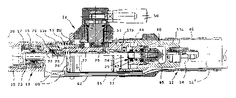
Fig. 1 shows a preferred embodiment of a connection coupling
in the form of a so-called quick-action connection coupling
which is coupled to a connection nipple indicated in this case
on the left side. The connection coupling 10 comprises a
tubular housing 11 with several mutually screwed-down housing
parts 11a, 11b and 11c, with the right housing part 11c being
used as the inlet region and the left region as outlet 13 for
the forwarding of the fluid to be transmitted to the
connection nipple 30. The inlet region 12 comprises a
connection adapter 14 to which a fluid line 12' can be
connected via a thread for supplying the fluid to be
transferred. The connection adapter 14 with an inserted filter
sleeve can be configured in adjustment to the fluid to be
transferred, especially to the desired feed pressure values,
opening cross sections, etc.
Several oblong collet chucks 15 are provided which are
arranged in tubular form and which can be spread in a radially
outward fashion shortly before the insertion on the connection
nipple 30. At the left outer end with inwardly crimped
surfaces, the collet chucks 15 comprise engagement profiles 17
which are configured so as to correspond to a groove-like
connecting profile section of the connection nipple 30. Its
configuration is also described in closer detail in the
aforementioned state of the art, so that any further
explanation can be omitted. It merely needs to be mentioned
for reasons of completeness that in the region of the outlet
13 a sealing piston 22 is inwardly guided which comprises at
its front face side a conical sealing surface 23 for sitting
close to a sealing ring of the connection nipple 30, so that
the gaseous andlor liquid fluid which substantially flows
along the central axis of the connection coupling 10 cannot
escape to the outside.
An outside sliding sleeve 18 is provided around the collet
chucks 15, which sliding sleeve is guided on the cylindrical
outside jacket of the housing part 11a which is on the left
side in this case and is pre-tensioned with pressure spring 19
in the direction away from the connection nipple 30. The
3
CA 02484236 2004-10-28
pressure spring 19 rests on a support ring 20 and thus pushes
the sliding sleeve 18 towards a control lever 50 with an
eccentric shaft 51. A data transmitter 60 is arranged as a
data interface on the circumference of the sliding sleeve 18.
Its data line 61 leads through a protective tube 62 to the
fluid line 12' in order to be fastened along the same, e.g.
with cable clips or straps. As a result, data from and to the
connection coupling 10 can be transmitted from a stationary
refueling system or can be sent to the same in order to
control the refueling pressure or flow quantities in
adjustment to the employed connection coupling 10 and/or
connection nipple 30 and their flow cross sections. Moreover,
the locking of the collet chucks 15 and the sliding position
of the sliding sleeve 18 can be checked in order to release
the refueling process with a respective signal.
The discharge valve 25 provided on the sealing piston 22 seals
by means of a sealing ring as valve seat 26 relative to the
sealing piston 22 in the closed position. The discharge valve
25 is pressurized by a pressure spring 28 which rests on a
switch slide 27 towards the right side. This discharge valve
25 ensures that in the uncoupled position (not shown here) or
shortly before the connection of the connection coupling 10
with the connection nipple 30 the fluid supplied through the
connection adapter 14 cannot flow out. The position of the
sealing piston 22 can also be determined by the data interface,
so that the data query preferably occurs via the data
transmitter at this time in order to avoid mistakes during
refueling.
The switch slide 27 is displaced during the uncoupling of the
connection coupling 10 from the connection nipple 30 along the
connection coupling axis and thus forms a ventilation valve 35
in combination with a sealing disk 24. The ventilation valve
35 and the switch slide 27 are actuated by pivoting the
control lever 50 because the eccentric shaft 51 is coupled
with the switch slide 27, namely through the engagement of
several bolts 29 which are in connection with an outside ring
slide 31.
4
CA 02484236 2004-10-28
As can be seen from the connection position of the connection
coupling 10 as illustrated here, the engagement profile 17 of
the collet chucks 15 is brought into engagement with the
connection nipple 30 during the insertion on the connection
nipple 30. In this position the data transmitter 60 is in
ultimate vicinity of the connection nipple 30, so that in the
manner of a proximity switch its magnetic properties for
example (or other parameters) can be queried in order to send
its size or connection dimensions via the data line 61 to the
base station. It can then choose the refueling values that
match the respective design of the connection nipple and
release or block the same. The data transmitter 60 can also be
arranged circularly about the sliding sleeve 18, as is
indicated by the dot-dash lines and can also be arranged as a
transponder. In this configuration, the data transmitter 60 is
preferably shrunk onto the sliding sleeve 18 or embedded in a
covering (e.g. in the manner of a shrink-down tubing or a
plastic housing).
By moving (pivoting by approx. 180°) the control lever 50 to
the position as shown here, the sliding sleeve 18 is pushed
over the collet chucks 15 and thus locked. This position can
also be determined by the data transmitter 60, especially when
the data transmitter 60 is fastened along the sliding sleeve
18 in a protruding way at the front end of the protective tube
62 in order to thus detect the displacing movement of the
sliding sleeve 18 relative to the housing 11.
When the pressure is applied (the beginning of the refueling
process), the sealing piston 22 is displaced at first to the
left (also under the action of spring 28). When it sits close
to the sealing surface 23, the valve seat 26 on the sealing
piston 22 and thus the discharge valve 25 are opened under
displacement of the sealing piston 22 to the right. In this
process, the engagement profile 17 has already engaged on the
correspondingly configured connecting profile section of the
connection nipple 30. As a result of the axial movement of the
sliding sleeve 18, the same engages over the radially outer
CA 02484236 2004-10-28
ends of the collet chucks 15, so that they are held in an
interlocked way on the connection nipple 30.
For releasing the connection coupling 10 and thus returning
the connection position as shown here to the opening position,
the sliding sleeve 18 is pushed back by the pressure spring 19
after the twisting of the control lever 50. After a short path,
the collet chucks 15 can spread again in a radially outward
manner. Since the fluid pressure was interrupted beforehand
(e.g. by closing the refueling valves), the sealing piston 22
is pushed here to the right in the direction towards the inlet
region 12. This position can also be detected by the data
transmitter 60.
The inlet region 12 further comprises an inlet valve 45 with
an associated valve seat 46 centrally in the housing 11 or the
housing part 11c of the connection coupling 10. The inlet
valve 45 is also axially displaceable by the control lever 50
and its eccentric shaft 51 by coupling with the switch slide
27. Said switch slide 27 displaces a valve slide 47 of the
inlet valve 45 to the opening.position via the sealing disk 24
in the illustrated connection position, so that the fluid
flowing in from the inlet region 12 can flow through the valve
slide 47 and a pass-through in the sealing disk 24 and the
tubular switch slide 27 towards the outlet 13.
When the connection coupling 10 is released, the switch slide
27 is displaced via bolt 29 to the left by twisting the
control lever 50 (by approximately 180°), so that the sealing
disk 24 can detach from the sealing engagement. The pressure
can thus degrade within the connection coupling 10 via the
pass-through slots to a pressure compensation chamber 44. Any
still applying pressure medium can thus flow via the pressure
compensation chamber 44 to a ventilation bore (not shown)
which extends parallel to the central fluid passage (through
valves 45, 35 and 25) in the housing part 11c of the
connection coupling 10. This ventilation bore can open into a
second line which is preferably arranged as a return hose and
is enclosed by a housing cap 48 like the feed line 12' in
6
CA 02484236 2004-10-28
order to be used as a handle for easy handling. The vent line
and the fluid line 12' which is connected to adapter 14 as
well as the data line 61 thus always extend substantially
parallel with respect to each other, so that a twisting of the
data line 61 during use is prevented.
7