Note: Descriptions are shown in the official language in which they were submitted.
CA 02484856 2004-10-15
CROSS-OVER RIB PLATE PAIR FOR HEAT EXCHANGER
BACKGROUND OF THE INVENTION
This invention relates to heat exchangers that are formed from plate pairs
s in which an internal flow path through the plate pair is defined by cross-
over ribs.
Heat exchangers are often formed from multiple plate pairs that are
stacked and brazed, soldered, or mechanically or otherwise joined and sealed.
In
some applications, for example in refrigerant evaporator systems, heat
exchangers are formed from stacked plate pairs that each define an internal U-
o shaped flow path for the refrigerant. In some plate pair heat exchangers
outwardly projecting ribs provided on each of the plates of a plate pair
cooperate
to form the internal U-shaped flow path. In such a ribbed plate construction,
the
ribs on each plate are angled in a common direction, such that when two plates
are arranged facing each other to form a plate pair, the internal groove
provided
15 by each rib on one plate crosses-over a number of the internal grooves
provided
by ribs on the facing plate, thereby forming the internal flow path.
Typically, at the
U-turn portion of the flow path, the angled ribs are longer in order to pass
the fluid
around the U-turn. Examples of cross-over rib heat exchangers can be seen in
U.S. Patent No. 3,258,832 issued July 5, 1966 and U.S. Patent No. 4,249,597
2o issued February 10, 1981.
In conventional designs for U-shaped flow path cross-over rib heat
exchangers, the internal fluid is subjected to a relatively large pressure
drop at
the turn-around portion of a plate pair flow path, relative to the total drop
across
the rest of the plate pair. Additionally, in conventional designs, the
internal fluid is
2s not always directed around the turn-around portion in the most efficient
manner
for promoting heat exchange. For example, fluid entering the turn-around zone
may have different phase characteristics based on a relative location of the
fluid
within the internal flow path. In conventional cross-rib plate designs, fluid
passing
around the turn-around portion is indiscriminately mixed without regard for
such
o differing characteristics. Thus, there is a need for a cross-rib type plate
pair heat
exchanger in which the pressure drop in transferring fluid around the turn-
around
portion is minimized and fluid is routed around the turn-around portion in a
-2-
CA 02484856 2004-10-15
pattern that increases heat exchanger efficiency.
SUMMARY
According to one example of the invention, there is provided a multipass
plate pair for conducting a fluid in a heat exchanger. The plate pair includes
first
and second plates, each plate having at least two longitudinal columns of
externally protruding obliquely angled ribs formed therein and separated by a
longitudinal flat section extending from substantially a first end of the
plate to a
terminus spaced apart from a second end of the plate. Each plate includes,
o between the terminus and the second end, a turn portion joining the two
longitudinal columns. The first and second plates are joined together about
peripheral edge sections thereof with the longitudinal flat sections abutting
each
other and the columns of angled ribs cooperating to form undulating first and
second internal flow channels separated by the abutting longitudinal flat
sections.
~5 The first and second internal flow channels each have an upstream area and
a
downstream area relative to a flow direction of an external fluid flowing over
the
plate pair. The turn portions of the plates cooperate to define at least a
first
internal flow path for directing fluid from the upstream area of the first
internal
flow channel to the downstream area of the second internal flow channel and a
2o second internal flow path for directing fluid from the downstream area of
the first
internal flow channel to the upstream area of the second internal flow
channel.
According to another example of the invention, there is provided a heat
exchanger including an aligned stack of U-flow tube-like flat plate pairs for
conducting an internal heat exchanger fluid between an inlet manifold and an
2s outlet manifold. Each of the plate pairs has an inlet opening and an outlet
opening for the internal fluid and an upstream edge and a downstream edge
relative to a flow direction of an external fluid over the plate pairs. Each
plate pair
includes first and second interfacing plates each having a longitudinal axis
and an
end, each of the plates having a longitudinal upstream column of outwardly
3o protruding ribs that are angled relative to the longitudinal axis, and a
longitudinal
downstream column of outwardly protruding ribs that are angled relative to the
longitudinal axis, the upstream column starting at one of the inlet and outlet
-3-
CA 02484856 2004-10-15
openings and terminating at a turn portion located adjacent the end and the
downstream column starting at the other of the inlet and outlet openings and
terminating at the turn portion, the upstream column being upstream of the
downstream column relative to the flow direction of the external fluid. The
turn
portion includes first and second outwardly extending ribs. The first and
second
plates are joined together with the angled ribs in the upstream columns of
each
plate communicating in a cross-over arrangement to define an upstream internal
flow channel for the internal fluid and the angled ribs in the downstream
columns
of each plate communicating in a cross-over arrangement to define a
o downstream internal flow channel for the internal fluid. The first outwardly
extending ribs cooperate to provide a first internal flow path for the
internal fluid
between an upstream side of the upstream internal flow channel to a downstream
side of the downstream internal flow channel, and the second outwardly
extending ribs cooperate to provide a second internal flow path for the
internal
fluid between a downstream side of the upstream internal flow channel and an
upstream side of the downstream internal flow channel.
According to another example of the invention, there is provided a U-flow
plate pair for conducting an internal fluid therethrough for use in a multi-
plate pair
heat exchanger having an upstream side and a downstream side relative to flow
of an external fluid between adjacent plate pairs of the heat exchanger. The
plate
pair includes first and second interfacing plates joined about peripheral edge
sections and along elongated central sections thereof, the plate pair
including an
elongated upstream side located between an upstream edge of the plate pair and
the joined central plate sections and a downstream side located between the
2s joined central plate sections and a downstream edge of the plate pair. The
upstream and downstream sides of the plate pair include a first internal flow
channel and a second internal flow channel, respectively, defined by obliquely
angled outwardly projecting interfacing ribs formed on the plates, the
interfacing
ribs on the first plate being oriented in an opposite direction than the
interfacing
so ribs on the second plate. The plate pair includes a turn-around end
defining a U-
shaped first internal flow path connecting an upstream area of the first
internal
flow channel to a downstream area of the second internal flow channel, and a
-4-
CA 02484856 2004-10-15
second internal flow path connecting a downstream area of the first internal
flow
channel to an upstream area of the second internal flow channel.
BRIEF DESCRIPTION OF THE DRAWINGS:
s Example embodiments of the invention will now be described, with
reference to the accompanying drawings, in which:
Figure 1 is a side view of an example embodiment of a heat exchanger;
Figure 2 is a first side edge view of a plate of the heat exchanger of Figure
1;
Figure 3 is an end view of the outside of a plate of the heat exchanger;
o Figure 4 is an end view of the inside of a plate of the heat exchanger;
Figure 5 shows the opposite side edge, relative to Figure 2, of a plate of the
heat
exchanger;
Figure 6 is a partial perspective view showing the outside of a plate of the
heat
exchanger;
15 Figure 7 is a partial end view of a plate pair of the heat exchanger; and
Figure 8 is a partial end view of a further example of a plate for use in the
heat
exchanger.
Like reference numerals are used throughout the Figures to denote similar
elements and features.
DESCRIPTION OF EXAMPLE EMBODIMENTS
Referring to Figure 1, an example embodiment of a heat exchanger,
indicated generally by reference 10, is made up of a plurality of plate pairs
20
formed of back-to-back plates 14 of the type shown in Figures 2 to 5. Plate
pairs
20 are stacked, tube-like members, formed from plates 14 having enlarged
distal
end portions or bosses 22, 26 having inlet 24 and outlet 28 openings, so that
fluid
-5-
CA 02484856 2004-10-15
flow travels in a generally U-shaped path through the plate pairs 20. In an
example embodiment, air-side fins 12 are located between adjacent plate pairs
20. The bosses 22 on one side of the plates are joined together to form an
inlet
manifold and the bosses 26 on the other side of the plates are joined together
to
form an outlet manifold. The heat exchanger 10 may include a longitudinal
inlet
tube 15 that passes into the manifold openings 24 in the plates to deliver an
incoming fluid, such as a two-phase, gas/liquid mixture of refrigerant, to one
side
of the heat exchanger 10. The heat exchanger 10 can be divided into multiple
parallel plate pair sections, with fluid routed serially through the various
sections
~o to ultimately exit from an outlet fitting 17 located at the same end of the
heat
exchanger 10 as an inlet fitting. Alternatively, the outlet and inlet fittings
may be
located at different ends or in different locations of the heat exchanger. The
actual circuiting used between plate pairs 20 is not critical and the plate
pair
configuration described herein can be used with many different configurations
of
U-flow stacked plate type heat exchangers. Although the heat exchanger 10 is
shown in the Figures with the inlet and outlet manifolds upwards oriented, the
heat exchanger 10 may often be oriented with the inlet and outlet manifolds
downwards.
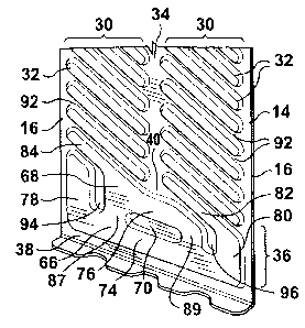
With reference to Figures 2 to 7, each plate pair 20 is formed from a joined
2o pair of elongated plates 14. In an example embodiment, the two plates 14 in
a
plate pair 20 are identical, with one plate being rotated 180 degrees about
its
longitudinal axis relative to the other. In this respect, Figure 3 shows the
outside
of a plate 14, and Figure 4 shows the inside of an identical plate 14 rotated
180
degrees relative to the plate shown in Figure 3. The plates 14 of Figures 3
and 4
2s are joined together to form a plate pair 20. Each plate 14 is substantially
planar,
with a flat outer edge portion 16 extending about its periphery. Each plate 14
includes two longitudinal columns 30 of outwardly protruding obliquely angled
ribs
32 that are separated by a longitudinal central flat section 34 that extends
from a
first or manifold end 42 of the plate to a terminus 40 that is spaced apart
from a
3o second end 38 of the plate. The central flat section 34 and the flat outer
edge
portion 16 are located in a substantially common plane, with ribs 32
protruding
outward from such plane to define inwardly opening grooves 18. In an example
-6-
CA 02484856 2004-10-15
embodiment, all of the ribs 32 on the plate 14 are oriented in a common
direction,
at an oblique angle relative to the elongate side edges of the plate. In some
example embodiments, however, each column could include multiple sections of
parallel ribs, with adjacent sections of ribs being oriented at different
angles. The
s ribs 32 in each column 30 extend from the central flat section 34 out to a
respective peripheral edge portion 16. Within each column, the ribs 32 are
each
separated by external valleys or grooves 92 that are in the same plane as flat
outer peripheral section 16 and flat central section 34. The columns 30 of
angled
ribs 32 terminate prior to the second plate end 38, and each plate 14 includes
a
~o turn portion 36 between the central flat section terminus 40 and the second
plate
end 38.
The plates 14 of a plate pair 20 are sealably joined together with their
respective peripheral edge portions 16 and central flat sections 34 aligned
and
abutting each other, and with the angled ribs 32 cooperating in a cross-over
~s arrangement to form undulating first and second internal flow channels 44,
46
through the plate pair 20 on opposite sides of the central flat sections 34.
The
turn portions 36 in the plates 14 cooperate to provide a first or outer
internal fluid
flow path 62 and a second or inner internal fluid flow path 64 between the
internal
flow channels 44, 46.
2o Figure 7 illustrates the cooperation of ribs 32 and turn portions 36 in a
plate pair 20, with the ribs 32 of a hidden plate 14 of the plate pair being
shown in
phantom lines. When installed in a vehicle, the heat exchanger 10 will
typically be
oriented so that air will flow through the air side fins 12 between the plate
pairs
20. Thus, with reference to Figure 1, the direction of air flow will be
substantially
2s perpendicular to the surface of the paper. Turning again to Figure 7, the
direction
of air flow over the outside of plate pair 20 is represented by arrows 56.
Accordingly, relative to the direction of air flow travel, the plate pair 20
has a
leading or upstream edge 58 and a trailing or downstream edge 60, first flow
channel 44 being upstream of the second flow channel 46. As used herein, the
3o terms "leading" or "upstream" and "trailing" or "downstream" are relative
to
direction of air flow through the plate pair 20, unless the context requires a
different interpretation. In the illustrated embodiment, the ribs 32 of one of
the
CA 02484856 2004-10-15
plates 14 (the visible plate in Figure 7) are all obliquely angled with their
downstream rib ends closer to the turn-around end 38 of the plate than their
upstream rib ends are. The ribs 32 of the other plate 14 (the hidden plate in
Figure 7) are all obliquely angled in an opposite direction with their
upstream rib
ends closer to the turnaround end 38 of the plate than their downstream rib
ends
are. In the illustrated embodiment, each rib 32 (except those ribs near the
manifold end 42 and those near the turnaround end 38) crosses over or
interacts
with four ribs 32 on the other plate 14 of the plate pair 20. In other example
embodiments, there may be more or less than four cross-over points between
~o opposing ribs. As best seen in Figures 3 and 4, in the illustrated
embodiment,
three of the ribs 32 near the manifold end 42 ace joined by joining ribs to 72
to the
inlet and outlet openings 24, 28, thus providing a path for fluid to enter and
exit
the flow channels 44, 46.
The tum-around portions 36 of plates 14 of a plate pair 20, each include
first and second outwardly protruding ribs 66, 68 that cooperate to provide
the
first and second internal flow paths 62 and 64, respectively, that connect the
internal flow channels 44, 46. The first turn-around rib 66 is located closer
to the
outer edges of the plate 14 than the second turn-around rib 68. The first and
second ribs 66, 68 each include central horizontal rib portions 74, 76,
2o respectively, that are substantially parallel to each other and to the end
38 of the
plate 14 and which are located between the terminus 40 of the central flat
section
34 and the plate end 38. The central rib portions 74, 72 are interspaced by a
flat
diving section 70 that is in the same plane as peripheral edge section 16 and
the
central flat section 34 such that the flat dividing sections 70 of the plates
14 in a
2s plate pair 20 abut together and separate central portions of the first and
second
internal flow paths 62 and 64 from each other. In the illustrated embodiment,
the
flat dividing sections 70 do not completely separate the flow paths 62 and 64,
and
short connecting paths 86 and 88 are provided between the flow paths 62 and
64.
3o As best seen in Figure 7, a first vertical rib portion 78 extends
substantially
parallel to one longitudinal edge of the plate 14, orthogonally from one end
of
horizontal central rib portion 74, and a second vertical rib portion 80
extends
_g_
CA 02484856 2004-10-15
substantially parallel to the opposite longitudinal edge of the plate 14
orthogonally
from the other end of horizontal central rib portion 74. Vertical rib portions
78 and
80 are separated from the central rib portion 76 by vertical flat plate
sections 94
and 96, which are in the same plane as edge section 16 and elongate central
section 34. Angled rib portions 82 and 84, which are parallel to angled ribs
32,
extend from rib portions 80 and 76, respectively, into respective rib columns
30.
Rib portions 74, 78 and 80 of facing plates 14 of a plate pair 20 define the
first
flow path 62. The first flow path 62 is, in an example embodiment, U-shaped
and
closely follows the outer edges around the turn-around end of the plate pair
20,
~o thereby ensuring that the internal fluid gets to the corner areas of the
plate pair
14. Additionally, the outer first flow path 62 directs internal fluid from an
upstream
area 48 of the first flow channel 44 to a downstream area 54 of the second
flow
channel 46. The inner second flow path 64, which is also U-shaped in the
presently described embodiment, directs internal fluid from a downstream area
50 of the first flow channel 44 to an upstream area 52 of the second flow
channel
46, as indicated by the flow arrows 90 shown in Figure 7.
. When heat exchanger 10 is in use, for example as an evaporator, the
temperature difference between the external air and an internal refrigerant
fluid at
the upstream side of the first flow channel 44 will typically be much greater
than
2o the temperature difference at the downstream side of the first flow channel
44,
with the result that by the time the internal fluid reaches turn-around
portion 36
the liquid phase component of the two phase internal fluid is concentrated
more
in the downstream area 50 of the first flow channel 44 than the upstream area
48.
In order to improve the evaporation rate, it is desirable to transfer as much
2s of the liquid phase component of the internal fluid from the first flow
channel 44 to
the leading edge of the second flow channel 46, as the temperature
differential
between the external air and the internal fluid will typically be greater at
the
upstream edge of the second flow channel than the downstream edge thereof.
The plate pair configuration described herein addresses this desirable feature
by
3o directing, through the inner flow channel 64, fluid from the downstream
area 50 of-
the first flow channel 44 to the upstream area 52 of the second flow channel
46,
and by directing through the outer flow channel 62, fluid from the upstream
area
_g_
CA 02484856 2004-10-15
48 of the first flow channel 44 to the downstream area 54 of the second flow
channel 46. This reduces mixing of the refrigerant fluid from the upstream and
downstream areas of the first flow channel 44. In other words, in evaporator
applications, the multiple turn-around flow paths of the presently described
s example embodiment directs the upstream portion of the first pass to the
downstream portion of the second pass and the downstream portion of the first
pass to the upstream portion of the second pass. As the upstream portion of
the
first pass is depleted of liquid refrigerant relative to the downstream
portion
because of the greater air-to-refrigerant temperature difference at upstream
edge
of a pass as compared to the downstream edge, it is beneficial to direct the
relatively liquid rich downstream portion of the first pass to the upstream
portion
of the second pass to take advantage of the larger air-to-refrigerant
temperature
difference at the upstream edge of the second pass as compared to the
downstream edge.
As indicated above, in some example embodiments short connecting
paths 86 and 88 are provided between the flow paths 62 and 64. The connecting
paths 86 and 88 are formed from externally protruding rib portions 87 and 89.
As
noted above and as shown in Figure 1, in an example embodiment air side fins
12 are located between adjacent plate pairs. The fins are secured to and
2o supported by the outer surfaces of ribs 32, 66 and 68. One function of rib
portions
87 and 89 is to provide support for the external air fin 12 that would
otherwise
have a long unsupported distance if flat section 70 were extended all the way
from plate area 94 to plate area 96. Generally, the mixing of fluid between
first
and second flow paths 62 and 64 through connecting paths 86 and 88 will be
quite low as the paths 86 and 88 connect areas of substantially equal
refrigerant
pressure and the connecting paths 86 and 88 are generally perpendicular to
flow
paths 62 and 64. Thus, the refrigerant fluid flowing through the flow paths 62
and
64 substantially by-passes the connecting paths 86 and 88 such that flow paths
62 and 64 are effectively separate from each other in the turn-around end 36.
in
3o some embodiments, paths 86 and 88 are omitted.
In an example embodiment, turn-around ribs 66, 68 and the angled ribs 32
that feed into the turn-around ribs 66, 68 have cross-sectional dimensions
that
-10-
CA 02484856 2004-10-15
are selected to reduce pressure drop in the internal fluid flowing around the
turn
portion of the plate pair.
With reference to Figure 6, as noted above, the ribs 32 are each separated
by external valleys or grooves 92 that are in the same plane as flat outer
peripheral section 16 and flat central section 34. An inner end of each groove
92
intersects with central section 34, and an outer end intersects with the outer
peripheral section 16. This provides a continuous drainage surface such that
condensate forming on the outer surface of the plate 12 can drain off through
the
grooves 92 (which will typically be spaced from the fin 12) to the downstream
1o edge of the plate. In one example embodiment, ribs 32 have a larger
external
surface area than grooves 92, thereby increasing the surface area contact
between the internal fluid carrying ribs 32 and the air- side fin 12.
In some embodiments, the heat exchanger 10 may have stacked plate pair
sections in which the internal fluid flows in the opposite direction of that
shown in
Figure 7, with the internal fluid first passing through the downstream or
second
flow channel 46, then through flow paths 62 and 64, and then into the upstream
or first flow channel 44.
The plates 14 may be formed in a variety of ways - for example they could
be made from roll formed or stamped sheet metal or from non-metallic
materials,
2o and could be brazed or soldered or secured together using an adhesive,
among
other things. Although the plates have been shown as having only two flow
paths
62, 64 between the first and second flow channels 44, 46, more than two flow
paths could be provided between the flow channels. The plates 14 have been
shown as having two passes; however the turn portion configuration described
herein could also be applied to plate pairs having more than one pass.
In some example embodiments, more than two turn-around flow paths are
provided between the first and second flow channels 44, 46. By way of example,
Figure 8 shows a further plate pair 100 that can be used in heat exchanger 10.
The plate pair 100 is-substantially identical to plate pair 20, except that
the plates
14 are configured to provide three parallel flow paths 102, 104 and 106
-11-
CA 02484856 2004-10-15
connecting the first and second flow channels 44, 46. In the embodiment of
Figure 8, outwardly protruding ribs 108 formed on the interfacing plates 14 of
the
pair 100 cooperate to provide first U-shaped flow path 102 for directing fluid
from
the upstream side of first flow channel 44 to the downstream side of the
second
s flow channel 46. Similarly, ribs 110 on interfacing plates 14 cooperate to
provide
second U-shaped flow path 104 for directing fluid from a middle area of the
first
flow channel 44 to a middle area of the second flow channel 46. Ribs 112
cooperate to provide third flow path 106 for directing fluid from a downstream
side of the first flow channel 44 to an upstream side of the second flow
channel
46. The use of additional flow paths allows for greater control over the
transfer of
fluid from specific exit areas of the first channel 44 to specific entry areas
of the
second channel 46. Generally, the choice between two, three, or more parallel
flow paths will be related to the overall width of the plates and to the
refrigerant
mass flow rate (in an evaporator application). Depending on the application,
1s relatively wide plates having high refrigerant flow rates may benefit from
more
parallel paths, whereas for narrower plates two paths may be sufficient.
As will be apparent to those skilled in the art in the fight of the foregoing
disclosure, many alterations and modifications are possible in the practice of
this
invention without departing from the spirit or scope thereof. The foregoing
2o description is of the preferred embodiments and is by way of example only,
and is
not to limit the scope of the invention.
-12-