Note: Descriptions are shown in the official language in which they were submitted.
CA 02484883 2004-11-05
WO 03/094816 PCT/US03/12795
Cross Reference to Related Applications
1. N/A
BACKGROUND OF THE INVENTION
Field of the Invention
Z. The invention relates to patient safety and controllers, and, more
specifically, to a patient
lifting apparatus and a controller that permits operation of a patient lifting
mechanism within
a specified safe range of operation.
Description of the Background
3. It is well known that persons confined to a bed due to illness, age,
accident, or injury and so
forth possess such limited mobility that movement ox transfer is extremely
difficult.
Improper transfer can result in serious complications to the individual and
the caregiver. For
instance, the need to move a patient immediately after an operation may be
necessary, yet is
a dangerous proposition, as any movement of the body may undo a surgeon's most
careful
work. Just as important is the need to transfer a bed ridden person for
bathing o~ exercise so
as to facilitate recovery.
4. In a hospital setting, a transfer is typically performed by a number of
hospital workers, in
order to comfortably lift a patient from one position to another. If the
transfer is made only
by hand, the hospital personnel risk back injury. If the transfer utilizes too
few personnel, or
CA 02484883 2004-11-05
WO 03/094816 PCT/US03/12795
requires reaching in an awkward position, the personnel may risk body strain.
Further,
despite the number of personnel employed to assist in the transfer, the
patient is susceptible
to injury from anyone who touches or lifts incorrectly.
5. For these reasons, a number of devices have been developed for lifting and
lowering of
incapacitated persons from a position in a bed, chair, bath or the like, such
as a patient lift
device having a base frame having vertically oriented guideposts, wherein a
carriage
assembly moves along the guideposts in response to an operator applied control
signal. An
arm assembly projects over the person placed into a sling for lifting. Such a
device may
require sufficient size to accomplish the intended service, namely, lifting.
In particular, the
device may employ elongated legs and a boom that is necessary to lift a
patient. This may
prevent the device from being easily transferred or stored. The length of the
components are
necessary so that the apparatus can fit beneath a bed or chair, yet provide
sufficient support
during the lifting process.
6. Another example of a patient lift and transfer apparatus includes a unitary
frame having a
caster wheel equipped U-shaped horizontal disposed frame. Again, the legs of
this apparatus
are capable of being placed beneath a patient's bed providing sufficient
support for the lifting
device as well as the patient. However, no provision is made for storage or
transportation of
the apparatus.
2
CA 02484883 2004-11-05
WO 03/094816 PCT/US03/12795
7. Another apparatus is based upon electrical motors to provide assistance in
patient
movement, wherein the arm members telescope and then retract. This apparatus
does not
include the retraction of the arms for purposes of storage or transportation.
8. A lifting device having leg support structures in the form of telescoping
leg assemblies
capable of extension and divergence is stable and may provide a safe and
effective means of
lifting patients. An example of such a lifting device is provided in U.S.
Patent No.
6,026,523, incorporated herein by reference in its entirety. The 1i$ing device
of this patent
meets the particular problems commonly found in hospitals and convalescent
homes,
wherein short term lifting capabilities are necessary. Unique to this lifting
device is the
ability to lift up to six hundred pounds, yet retract in size for puxposes of
transporting and
storage. In operation, the support legs provide about a seventy eight, inch
stance when fully
extended. In a retracted position, the support legs telescope together,
leaving a frame
footprint of approximately fifty two inches. The lifting device includes a
miniature crane
having a rotatable column with a lifting arm that can be raised and lowered at
the upper end.
The column is rotatably coupled to the portable base frame, and is operably
attached to an
electric motor driven linear actuator that enables independent and reversible
rotation of the
column, in order to facilitate placement of the end of the lifting arm above
the patient's bed,
in order to permit eventual transport of the patient away from the bed, Such
as by, for
example, a chair, gurney, or wheelchair. An additional electric motor driven
linear actuator
may make raising and lowering of the lifting arm effortless.
3
CA 02484883 2004-11-05
WO 03/094816 PCT/US03/12795
9. The support legs may be further extended outwardly from the frame once the
apparatus is
positioned at the bedside. This feature allows for ease of movement to various
sites, but
allows for greater stability during use. Additionally, the support legs, which
are normally
parallel with respect to each other, are pivotally attached to the base frame
and operatively
associated with an additional electrically driven linear actuator.=Operation
of this actuator
enables angular displacement of the leg assemblies, so as to cause divergence
or
convergence thereof. This featuxe provides a safe and efficient means to
ensure the stability
of the entire apparatus during a lifting procedure. Additionally, since the
extension and
divergence of the support legs is carried out beneath the bed, access to the
bed and the
patient is not hampered in any way.
10. Once the apparatus is in position, the unit can be easily secured by
locking the frame
mounted wheels. In an embodiment, the apparatus uses four wheels, two of which
are
lockable caster wheels similar to those found on stretchers, positioned at the
rear of the
support base. Two additional casters are affixed to the lower portion of the
support legs at
their outermost or distal end.
11. With the support legs in an extended and divergent position, an operator
can maneuver the
lifting arm over a patient's bed, wherein a hook device is available for
attaching to a patient
sling. The sling is placed beneath the patient so as to facilitate support
during transfer, The
combination of actuator and lifting arm is capable of lifting up to six
hundred pounds
through an angular range of motion of about 50-90 degrees along the vertical
axis. The
column is further able to rotate about its axis on the order of about +1- 30
degrees from a
starting position, e.g. perpendicular to the rear edge of the support base, in
either a clockwise
4
CA 02484883 2004-11-05
WO 03/094816 PCT/US03/12795
or counterclockwise direction. Angular rotation of the column is performed by
use of an
electric motor coupled to a linear actuator.
12. An operator of the lifting device controls operation by sending control
signals to the
controller that, in turn, forwards control signals to actuators to generate
the movement of the
lifting device in accordance with the control signal. However, the methodology
used to
provide the control signal from the operator, such as a hand-held control pad,
having thereon
a plurality of control buttons, such as extend, lift, right, left, up, down,
and the like, may be,
intentionally or unintentionally, misused by the operator. In. such an
instance, the lifting
device may not operate properly or safely. For example, if a safe footprint of
the lifting
device is not set before attempting a lift and transfer of the patient, such
as by a failure to
extend the base, or a failure to sufficiently open the legs, the base may
allow for tipping over
of the li$ing device, thereby possibly harming the patient or the operator.
When the legs are
completely open angularly , and when the legs are completely extended
linearly, a safe
footprint is set, thereby allowing for lift and transfer with no tipping. -
13. Recommendations to the operator, such as in the form of extensive in-
service training
emphasizing proper setup, andlor instructions included with signage placed on
the lifting
device, can assist in insuring proper setup of the lifting device. However,
such training or
informational methodologies nonetheless allow for human error. Thus, an
automated device
and method is needed to cornpleteiy insure proper setup of the lifting device.
SL~tMAR~ OF THE IhTVENTION
14. A computerized controller that limits the movement of a patient lifting
device, wherein the
controller is operated in a normal mode to sense the lateral rotation of a
lifting arm that lifts
CA 02484883 2004-11-05
WO 03/094816 PCT/US03/12795
patients and the linear displacement of extendable support legs for said
lifting device and the
angular diversion of said support legs, is disclosed. The controller ixahibits
movement of said
lateral rotation of a lifting arm in response to the linear displacement and
the angular
diversion of the support legs to prevent tipping the lifting device.
15. A computerized controller that limits the movement of a patient lifting
device, in a normal
mode of operation, whereby tipping of the lifting device is prevented, is also
disclosed. The
controller is operated in a bypass mode to override the normal mode wherein
the patient
lifting device may be operated during a setup and breakdown operation to
permit
construction and disassembly of the patient lifting device.
BRIEF DESCRIPTION OF THE DRAWINGS
16. Understanding of the present invention will be facilitated by
consideration of the following
detailed description of a pxeferred embodiment of the present invention, taken
in conjunction
with the accompanying drawings, in which like numerals refer to Iike parts and
in which:
17. FIG. 1 is a side view of the lifting device with the support legs extended
and the lift
arm in a horizontal position;
18. FIG. 2 is a top view of the lifting device with the support legs extended
and diverged;
19. FIG. 3 is a cross-sectional top view of the support base;
20. FIG. 4 is a back view of the device;
21 o FIG. 5 is a top view of the device showing the support leg lineax and
divergence
range of travel including, in phantom, the support legs closed and fully
retracted;
22. FIG. 6 is a top view of the device showing the Lift arm assembly
rotational range of
travel.
6
CA 02484883 2004-11-05
WO 03/094816 PCT/US03/12795
DESCRIPTION OF THE INVENTION
23. It is to be understood that the figures and descriptions of the present
invention have bean
simplified to illustrate elements that are relevant for a clear understanding
of the present
invention, while eliminating, for purposes of clarity, many other elements
found in a typical
patient-safety or lifting device. Those of ordinary skill in the art will
recognize that other
elements are desirable andlor required in order to implement the present
invention.
However, because such elements are well known in the art, and because they do
not
facilitate a better understanding of the present invention, a discussion of
such elements is not
provided herein. The disclosure hereinbelow is directed to alI such variations
and
modifications to lifting and/ox control devices for motor positioning as
known, and as will be
apparent, to those skilled in the art.
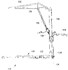
24. Referring now to FIG. 1, shown is an embodiment of a lifting device 110,
including a
support base 112 having two locking rotatable casters 114 secured to the
bottom of base 112.
Foot operated levers 116 may provide simplifted engagement of wheel locks.
Rotatable
column 120 extends vertically from, and is mechanically linked to, support
base 112 via
column mount 314 (see FIG. 3). Lift arm assembly 122, shown in a horizontal
orientation,
may be pivotally attached to column 120 at first pivot point 124 and second
pivot point 126.
Extension of the Iift arse from about 29 degrees above, to about 45 degrees
below, the
horizontal reference position shown may be accomplished by, for example,
electric motor
driven linear actuator 128. The actuator 128 acts a lifter, providing power to
extend or retract
actuator rod 130, thereby raising or lowering lift arm assembly 122 actuator
rod 130.
7
CA 02484883 2004-11-05
WO 03/094816 PCT/US03/12795
25. Referring now to FIG. 2, pivotally mounted to the support base 112 may be
extensible legs
118 and 118A having a rotatable caster 220 mounted at a distal end 222
thereof. Each of the
legs 118 and 118A may be formed of a leg weldment 224 and a leg extension 226
that
together define a telescoping leg assembly 234 capable of reversible extension
from the
support base. The leg extension 226 may be in a nesting relation with the leg
weldment 224,
and may include a leg cylinder bracket 228 that is operatively associated with
the distal end
portion 236 of telescoping actuator rod 230. The proximal end 238 of the
telescoping
actuator rod is operatively associated with a linear actuator 232 for
reversible extension of
the Ieg assembly 234.
26. Referring now to FIG. 3, a top cross-sectional view of support base 112
shows actuator
motors 232 that each operate independently for extension of legs 118 and 118a
as desired.
An additional motor 310 may be mechanically linked to each of legs 118 and
118A.
Activation of motor 310 causes actuator rod 312 to pivot the legs outwardly
from the initial
parallel orientation to a point where the legs circumscribe about a 40 degree
to a 90 degree
angle. The operator is thus able to reversibly extend each of legs 118, 118A
independently,
while causing the legs to reversibly diverge from one another. This allows the
device to be
easily transported from one patient area to another when in the compact
retracted
configuration.
27. Once in position at the patient's bedside, the legs may then be extended
and diverged so as to
define a longer and wider footprint, thereby providing enhanced stability
during the patient
lifting process. Column mount 314 retains the column in a vertical orientation
with respect
8
CA 02484883 2004-11-05
WO 03/094816 PCT/US03/12795
to the support base 112, while allowing the column to rotate about its axis.
Electrically
driven linear actuator 316 may act as a column 120 rotator that reversibly
extends an
actuator rod 318 that is pivotally attached to column 120 via an attachment
arm 320. The
column may, for example, have a total angular sweep of about +/- 30 degrees to
about +/- 90
degrees to either side of a reference position whexein it is perpendicular to
a plane defzned
by the handle 410 (see FIG. 4).
28. Refernng now to FIG. 4, a back view of the device 110 shows U-shaped
handle 4I0 that is
attached to support base 112 and further attached to column 120 via a handle
strap 412. The.
handle encloses a basket area 410 that may contain a controller 412 for
transmitting signals
to the various actuator motors, and a battery 414 for powering the various
electrically
controlled devices. A remote controller 416 may be provided in electrical
communication
with the control panel. The remote controller may contain the necessary
switching devices
to control up and down movement of the lifting arm, clockwise and
counterclockwise
rotation of the column, extension and retraction of each of the legs
individually, and
divergence and convergence of both legs simultaneously, for example.
29. Referring now to Figure 5, the extendable Iegs l I8 and 1 I8a are shown in
phantom in the
stowed position, such as before deployment. Using actuator 310 of Figure 3,
the extendable
legs 118, 118a, may be extended until each leg reaches a fully diverged and
deployed state.
For example, legs 118 and 118a may extend together linearly, such that an
angle A covers,
for example, the range of 0 degrees to 45 degrees. In an embodiment, both legs
118 and
118a may be extended simultaneously, such that angle A is roughly equal to
angle ~. The
9
CA 02484883 2004-11-05
WO 03/094816 PCT/US03/12795
total divergence of the legs 118, 118a may be represented as angle C, and as
an exemplary
embodiment, angle C may have a range of, for example, between 0 degrees and 90
degrees.
Further, using actuators 232, 232a, both legs 118, 118a may be extended from
length L1 to
length L2. The activation of all, or a portion of, the actuators may be
monitored by a
programmable controller 412, such as a memory device activated switch, a
programmable
logic controller, or other microcontollers apparent to those skilled in the
art.
30. Using actuator 316 of Figure 3, the lift arm assembly 122 may be rotated.
Referring also to
Figure 6, lift arm assembly 122 may be moved from its center position to a
position
indicated in phantom in Figure 6 as 122a. This rotation is represented as
angle D. Similarly,
the lift arm assembly 122 may be rotated to a position represented in phantom
in Figure 6 as
122b, thus moving through angle E. The full angle of motion of lift arm
assembly 122 is
thus represented as angle F. In an exemplary embodiment, angle F may be, for
example, a
maximum of +/- 60 degrees.
31.. Safety considerations may be imposed, such that the rotation of lift arm
assembly 122
through angle F may be limited so as not to allow the lifting device to tip
over under load.
This limiting may be performed, for example, by a limiting of actuators,
dependent on
predetermined criteria, such as a limiting by controller 4I2. For example,
angle F may be so
limited at a point when angle C of Figure S is a predetermined minimum value,
as
determined by a sensing of angle C by controller 412, such as wherein the
controller 416
monitors the activation of an actuator. As an additional constraint, angle F
of Figure 6 may
CA 02484883 2004-11-05
WO 03/094816 PCT/US03/12795
be restricted to some minimum value if the combination of angle C is below
some minimum
value, and the length of extendable legs 228 is below some minimum value of
L2.
32. In an exemplary embodiment, the rotation of lift arm assembly 122 of
Figure 6 may be
limited such that a maximum value of angle F is 10 degrees (+/- 5 degrees from
center axis)
for a divergence angle C of less than about 66 degrees, and/or for an
extension length L2 of
Figure 5 of less than, for example, 95 % of the full extended length L2. These
restrictions
may be imposed on the operation of the lifting device so as to prevent
tipping. It should be
noted that lift arm assembly 122 may be lowered and elevated by use of
actuator 128 at any
time without restriction.
33. In this exemplary embodiment, angle F may be controlled by an actuator
having a stroke of
3.94", and this stroke may be limited to 1.91" for proper operation. Thus,
full retraction of
the actuator may cause an angle F of -30 degrees from center axis, and a full
stroke of
actuator to 1.91" may cause an angle F of +30 degrees from center axis.
However, in
accordance with the status of length L2, and/or the openness of the angle C,
the controller
412 may limit the actuator to function, for example, over a stroke of 1.08" +
0.166" right and
0.157" left, thereby limiting angle F to +/- 5 degrees from center axis,
wherein the controller
assesses length L2 to be less than 95% of full length L2, and/or wherein the
controller 412
assesses the legs to be less than 95% open.
34. Fox example, in this exemplary embodiment, the actuator that opens and
closes the leg angle
C may be, for example, an actuator having a total stroke of 5.91 ", and an
install length of
11
CA 02484883 2004-11-05
WO 03/094816 PCT/US03/12795
12.21". Such an actuator may be fully extended when the legs are closed, and
fully retracted
when angle C approaches, for example, 70 degrees. Thus, the legs may be 9S%
open when
the stroke is down from 12.21" to 0.295". The actuators that extend the legs
outwardly may
have a stroke of, for example, 20.67", and may be at full stroke upon full leg
extension.
Thus, at 19.36" stroke, the controller 412 may assess the respective leg
contolled by the
respective actuator as being 9S% extended. Thereby, when at least one, or, for
example,
both, of these two 9S% minimum conditions are met, angle F may be allowed, by
the
controller 412, to exceed +/- S degrees from center. In this exemplary
embodiment, the
patient lift device may lift up to, for example, seven hundred pounds.
35. An additional restriction on operation to maintain operation of lift
device within safe
parameters may include inhibition of the retraction of the extendable legs,
and/or inhibition
of the closing of the angular divergence of the extendable legs, while
performing a lift of a
patient. Specifically, one embodiment may include the operational restriction,
by the
controller A.12, of inhibiting and/or preventing movement of the actuators
that control leg
extension andlor retraction, or of the actuators that control leg divergence
and/or closure
when the lift arm is rotated more than 5 degrees left or right of the center
location.
Equivalently, this occurs when the entirety of angle D or E of the lift arm
assembly exceeds
S degrees. Correspondingly, leg extension and leg divergence actuators may be
re-enabled if
the lift arm assembly is rotated to be within 5 degrees left or right of the
center axis.
36. The handheld controller x.16 of Figure 1 may be employed to provide an
operational safety
interlock to prevent patient lift and transfer outside of limit condition,
such as the limit
12
CA 02484883 2004-11-05
WO 03/094816 PCT/US03/12795
conditions on divergence angle and leg extension length discussed hereinabove.
User
control of all actuators in the lifting device may be provided by control pad
416. The safety
interlock within the controller 416 may operate by tracking the operation and
position of
actuators, and'by allowing operation of particular ones of the actuators only
upon proper
actuation of other actuators, for example, in accordance with information from
controller
412. The control device may include therein the digital controller 412 running
software that
provides the limitations of movement stated hereinabove. Software resident in
the controller
412 may track performance of all actuators in the lifting device, or only
actuators of interest
and the respective position indicators thereof, in order to ensure safe
operation of the lifting
device. The software, and/or the controller 412, and/or the handheld
controller 416, may
track proper and safe operation, such as by monitoring the output of at least
one read switch
engaged and aligned to monitor the position or performance of certain ones of
the actuators,
as discussed hereinabove. The handheld controller 416 may incorporate a keypad
and may
incorporate a display indicating some indicia of operation of the lifting
device, such as, for
example, the rotational position of the lift arm assembly, the angular
displacement of the
extendable legs, and the linear displacement of leg extension.
3"T. In one embodiment of the present invention, the handheld controller 416
and/or the
controller 412 monitors position sensors located in the lifting device to
ensure that the
hereinabove safety limits are met. For example, reed, limit, magnetic, Hall
effect or other
proximity switches may be used to sense when the extendable Legs axe
sufficiently diverged
enough to allow safe operation. In addition to these sensors, sensors may be
used to sense
when the extendable legs are sufficiently deployed linearly to allow safe
operation of the
13
CA 02484883 2004-11-05
WO 03/094816 PCT/US03/12795
lifting device. Once again, sensors may be used to sense the rotational
location of the lifting
arm so as to prevent rotation of the lifting arm when the extendable legs are
not fully
deployed in at least one of either length or angular displacement.
38. In one embodiment, a digital position indicator may be used for the leg
angular divergence,
extension, and lifting arm rotation position. For example, a digital encoder
may be used to
indicate the actual position of the legs or lift arm assembly and make the
information
available to the digital controller.
39. In one embodiment, rotary digital encoders may be used on all rotary type
actuators. In this
embodiment, the digital encoders indicate the number of revolutions, for
example, in degrees
or binaxy number count, to indicate the position of screw-type xotary
actuators in order to
limit the overall operation of the lifting device to be within the hereinabove
safety limits. In
this embodiment, the confiroller 412 would receive digitized position
information from all
actuators in the lifting device and translate that information to relevant
positional
information to ensure operation within safe operating limits. Tt is well
understood by those of
skill in the art that the actuators may be of the rotary or linear type, and
that digitized
position information may be obtained via any of the commercially available
digital position
sensing devices, including linear and rotary encoders.
40. In an additional embodiment of the present invention, the handheld
controller 416 and/or the
controller 412 may monitor variables, such as sensors, such as weight
transducers, and/or
such as current drawn by an actuator, in order to monitor weight present on
the hook device
14
CA 02484883 2004-11-05
WO 03/094816 PCT/US03/12795
of the lift arm. Movement, such as retraction of legs, closure of leg
divergence, or the like,
may thereby be limited, as set forth hereinabove, when a patient weight is
sensed on the lii~
arm. The weight sensing may be calibrated, such as to account for the weight
present on the
lift arm when no patient is on the lift arm, such as, for example, the 20-30
lbs that may be
present due to certain embodiments of the hook device.
41. A bypass mode of operation may be implemented in the controller 4I6 to
facilitate
breakdown and setup of the lifting device. The use of the bypass mode for
actuating
movement beyond the hereinabove ranges constitutes a safety hazard should an
operator be
using the device to lift a patient. Therefore, a safety interlock may be
implemented in the
controller 416 to prevent inadvertent operation in the bypass mode. Irz one
embodiment, a
lockout keypad code may be entered in order to operate the unit in bypass
mode. ance in
bypass mode, an audible alarm may be sounded to alert or remind the operator
that the unit
is in bypass made, and is to be used only for breakdown and setup of the
lifting device. In
this embodiment, an additional keypad input may be required to exit the bypass
mode.
42. Tn one embodiment, a physical lockout key may be used to temporarily place
the unit in
bypass mode. Once again, upon placement into bypass mode, an audible alarm may
be
sounded to alert or remind the operator that the unit is in bypass mode to be
used only for
breakdown and setup of the lifting device. Exit from the bypass mode may be
obtained by
removal or reset of the physical key or key position. Those of skill in the
art will realize that
any form of safety interlock mechanism may be used. For example, a physical
key and key
position, physical or magnetic, a digital key code, or a key switch of limited
access on the
CA 02484883 2004-11-05
WO 03/094816 PCT/US03/12795
controller device are exemplary of such mechanisms.
43. In operation, it is recommended that a patient be placed upon a support
sling. The lift arm is
positioned above the patient and a lifting bar is properly positioned over the
support sling.
This configuration minimizes any swinging tendency as the support sling and
patient is
pulled upward. A hook for attachment to the support sling may be attached to
the end of the
lift arm assembly 122. While positioning the device it may be left free to
roll so as to more
easily align the end of the lift arm assembly above the patient. Once the
device is properly
located, the locking casters are engaged so as to prevent any undesirable
movement during
the lifting process.
44. It will be apparent to those skilled in the art that various modifications
and variations may
be made in the apparatus and process of the present invention without
departing from the
spirit or scope of the invention. Thus, it is intended that the present
invention cover the
modification and variations of this invention provided they come within the
scope of the
appended claims and the equivalents thereof.
1&