Note: Descriptions are shown in the official language in which they were submitted.
CA 02484888 2004-10-15
HIGH VOLUME ADJUSTABLE VACUUM ASSEMBLY
FOR A ROLL IN AN INTERFOLDING MACHINE
RELATED APPLICATIONS
[0001] This application claims the benefit under 35 U.S.C. ~ 119(e) of U.S.
Provisional Application Serial No. 60/511,960, filed October 16, 2003, the
entirety of which
is hereby incorporated herein by reference.
FIELD OF THE INVENTION
[0002] This invention generally relates to an interfolding machine for
interfolding
sheet or web material, and more specifically, to an interfolding machine that
includes an
assembly that provides on the fly adjustment for an on/off position of a
vacuum for
selectively holding and releasing of the sheet or web material on certain
rolls incorporated in
the interfolding machine.
BACKGROUND OF THE INVENTION
[0003] Interfolding of sheet material (e.g., napkins, paper towels, tissue,
etc.) is
frequently performed using a series of rolls that cooperate to sever web
material into sheets,
overlap the sheets, and interfold the overlapped sheets to form an interfolded
stack of sheets.
Certain of the rolls include a vacuum system having vacuum ports on the outer
surface of the
roll, which are selectively supplied with vacuum to hold and release the
sheets during
rotation of the roll.
(00066250.DOC / 2}
CA 02484888 2004-10-15
[0004] In a typical prior art system, a roll is internally drilled to route
air flow from
the roll surface to the roll sides. Stationary side valves are spring loaded
against the roll
sides to encapsulate the vacuum ports on the rolls sides. Each side valve is
in the form of a
plate which has a rectangular cross section, circular cavity machined into the
side of the
valve face, which bears against the roll side. The valve cavity matches the
ports in the roll
side. The valve cavity intersects a perpendicular supply port that interfaces
the valve with a
vacuum supply system. Partial segment slugs are positioned in the valve
cavity, so as to
correspond to vacuum on/off points in rotation of the roll. The slugs are held
in position
with bolts through slots in the outer sides of the valve.
[0005] While a system of this type functions adequately, it requires the
interfolding
machine to be stopped and the slugs manually moved within the slots in order
to alter the
on/off points of the vacuum supplied to the roll surface. Furthermore, the
thickness of the
side valve plate defines a bottleneck that limits the strength of the vacuum
that can be
supplied to the surface of the roll.
SUMMARY OF THE INVENTION
[0006] In accordance with the present invention, there is provided a valve
assembly to
regulate the supply of suction or vacuum communicated from a vacuum source,
such as a
vacuum pump, to a surface of a web or sheet handling roll. The valve assembly
is
stationarily mounted to the roll journal, and includes an outer slug and an
inner slug coupled
i00066250.DOC I 2}
CA 02484888 2004-10-15
by a pilot ring. A spool is mounted to the inner slug. The spool includes an
opening to
receive a draw of air through the outer and inner slugs. A cover or manifold
is coupled to the
spool, and includes a port that communicates with the vacuum source. The cover
and the
spool define a cavity, which communicates with the opening in the spool and
with the port in
the cover to define an air flow path from the roll surface to the vacuum
source. The outer
slug and the inner slug are configured to regulate the flow of air from the
roll surface into the
cavity. The outer slug and the inner slug are rotatably adjustable relative to
the spool and
relative to one another, to control the on/off positions at which suction or
vacuum is supplied
to the roll surface. The slugs are configured to be adjustable while the roll
is rotating, to
provide on-the-fly adjustment of the on/off positions. The cavity and manifold
design
significantly increases airflow volume over prior art systems.
[000] In accordance with another aspect of the invention, there is provided an
interfolding machine for handling and interfolding sheet or web material. The
interfolding
machine includes a rotating roll for holding and the releasing sheet or web
material. The
rotating roll generally includes a plurality of holes along an outer surface
for communicating
suction or vacuum to the sheet or web material. The interfolding machine
further includes a
valve assembly for the rotating roll, which includes an outer slug, an inner
slug, and a pilot
ring rotatably coupling the outer slug and the inner slug. The valve assembly
further
includes a spool mounted to the inner slug, and a cover or manifold coupled to
the spool.
The spool generally includes an opening, and the cover or manifold defines a
cavity within
(00066250.DOC / 2 f
CA 02484888 2004-10-15
which the spool is located. The cavity defined by the cover or manifold is in
communication
with the opening of the spool. The outer slug and the inner slug are rotatably
adjustable
relative to the spool and relative to one another,.
[0008] In accordance with a further aspect of the present invention, there is
provided a
method of regulating the supply of suction or vacuum to a surface of a
rotating roll having a
series of suction or vacuum ports that open onto the surface of the roll, and
suction or
vacuum supply passages that open onto a side of the roll. The method includes
the acts of
providing a vacuum source to draw air into the suction or vacuum ports of the
roll; drawing
the flow of fluid into through the passages and the openings in an outer slug
and an inner
slug into a cavity defined by a spool and a cover or manifold; and
communicating the flow of
fluid through the cover or manifold to the vacuum source. The method further
includes
rotatably adjusting the opening of the outer slug relative to the opening of
the inner slug
during rotation of the roll, i.e., while interfolding machinery is running, so
as to so as to
control the on/off positions at which suction or vacuum is supplied to the
surface of the roll.
(0009] Other objects, features, and advantages of the invention will become
apparent
to those skilled in the art from the following detailed description and
accompanying
drawings. It should be understood, however, that the detailed description and
specific
examples, while indicating preferred embodiments of the present invention, are
given by way
of illustration and not of limitation. Many changes and modifications may be
made within
{ooo6s2so.DOC r ay
CA 02484888 2004-10-15
the scope of the present invention without departing from the spirit thereof,
and the invention
includes all such modifications.
BRIEF DESCRIPTION OF THE DRAWINGS
[0010] Preferred exemplary embodiments of the invention are illustrated in the
accompanying drawings in which like reference numerals represent like parts
throughout. In
the drawings:
[0011] FIG. 1 is an isometric view of an interfolding machine employing a
vacuum
assembly in accordance with the present invention.
(0012] FIG. 2 is a schematic side elevation view of the interfolding machine
as shown
in FIG. 1.
[0013] FIG. 3 is an exploded isometric view of the components of the vacuum
assembly of the present invention, shown in combination with one of the rolls
of the
interfolding machine of FIG. 1.
[0014] FIG. 4 is an isometric assembly view of the vacuum assembly of the
present
invention, the components of which are shown in FIG. 3.
[0015] FIG. 5 is an enlarged exploded isometric view of the components of the
vacuum assembly shown in FIG. 4.
~ooosszso.ooc i z}
CA 02484888 2004-10-15
[0016] FIG. 6 is a cross-sectional view of the vacuum assembly along line 6-6
of FIG.
4
[0017] FIG. 7 is cross-sectional view of the vacuum assembly along line 7-7 of
FIG.
6.
[0018] FIG. 8 is a cross-sectional view of the vacuum assembly along line 8-8
of FIG.
6, showing the vacuum assembly in a first position.
[0019] FIG. 9 is a view similar to FIG. 8, showing the vacuum assembly in a
second
position.
[0020] FIG. 10 is a view similar to FIGS. 8 and 9, showing the vacuum assembly
in a
third position.
DETAILED DESCRIPTION OF THE PREFERRED EMBODIMENTS
1. Interfolding Machine
[0021] Referring to FIGS. 1 and 2, an interfolding machine 2S is operable to
convert a
web of material 30 into a stack of interfolded sheets of material shown at 32.
Interfolding
machine 2S generally includes a first pull roll 3S and a second pull roll 40
that receive the
web of material 30 along a path (illustrated by an arrow 42 in FIG. 2) from a
supply roll (not
shown) into the interfolding machine 20. The first and second pull rolls 3S
and 40 define a
nip through which the web of material 30 passes, and function to unwind the
web of material
{00066250.DOC / 2}
CA 02484888 2004-10-15
30 and feed the web of material 30 in a path (illustrated by an arrow 44 in
FIG. 2) toward a
nip defined between second pull roll 40 and a bed roll 45. The web of material
30 is then
advanced by bed roll 45 toward a knife roll 50. In a manner as is known, the
knife roll 50
cuts the web of material 30 into sheets, each of which has a predetermined
length, and the
bed roll 45 carries the sheets of material along a path (illustrated by arrow
52 in FIG. 2)
toward and through a nip defined between bed roll 45 and a retard roll 55,
which rotates at a
slower speed of rotation than the bed roll 45. In a manner as explained in
copending
application serial number filed fatty docket no. 368.033), the
retard roll 55 cooperates with a nip roller assembly 60 (FIG. 2) to form an
overlap between
the consecutive sheets of material. The retard roll 55 carries the overlapped
sheets of
material along a path (illustrated by arrow 68 in FIG. 2) to a lap roll 65.
[0022] The lap roll 65 works in combination with a count roll 75 to eliminate
the
overlap between adjacent sheets of material at a predetermined sheet count, so
as to create a
separation in the stack 32 of interfolded sheets discharged from the
interfolding machine 25.
The lap roll 65 carries the overlapped sheets 30 along a path (illustrated by
arrow 78 in FIG.
2) toward a nip defined between a first assist roll 80 and an adjacent second
assist roll 85.
The first and second assist rolls 80 and 85 feed the sheets of the material to
a nip defined
between a first folding roll 90 and a second folding roll 95.
{ooo~zso.~oc r z} 7
CA 02484888 2004-10-15
[0023] Referring to FIG. 2, the first and second folding rolls 90 and 95
generally
rotate in opposite directions (illustrated by arrows 96 and 98, respectively,
in FIG. 2) to
receive the overlapped sheets of material 30 therebetween. The periphery of
the first folding
roll 90 generally includes a series of the gripper assemblies 100 and a series
of tucker
assemblies 105 uniformly and alternately spaced to interact with a series of
gripper
assemblies 100 and tucker assemblies 105 of the adjacent second folding roll
95. The series
of alternately spaced gripper assemblies 100 and tucker assemblies 105 of the
first and
second folding rolls 90 and 95 interact to grip, carry, and release the sheets
of material in a
desired manner so as to form the desired interfolded relationship in the
sheets of material and
to form stack 32 of interfolded sheets. The folding rolls 90 and 95 may be
driven by a drive
system 110 having a drive belt assembly 115 (FIG. 1).
[0024] The stack 32 of interfolded sheets is discharged from between the first
and
second folding rolls 90 and 95 in a generally vertically-aligned fashion. The
stack 32 of
interfolded sheets may be supplied to a discharge and transfer system (not
shown), which
guides and conveys the stack 32 from the generally vertically-aligned
orientation at the
discharge of the interfolding machine 25 to a generally horizontally-aligned
movement. One
embodiment of a suitable discharge and transfer system is described in U.S.
Patent No.
6,712,746 entitled "Discharge and Transfer System for Interfolded Sheets,"
filed May 5,
2000, the disclosure of which is hereby incorporated herein by reference in
its entirety.
Another representative discharge and transfer system is illustrated in
copending application
{ooo~zso.noc i z~ 8
' CA 02484888 2004-10-15
~ r
serial no. filed fatty docket no. 368.005), the disclosure of which is
also hereby incorporated herein by reference in its entirety.
2. Vacuum Assembly
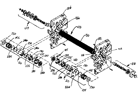
[0025] FIGS. 3-6 illustrate one embodiment of a vacuum valve assembly 20 in
accordance with the present invention, for supplying a suction or vacuum to a
surface of a
rotating roll 118. The rotating roll 118 can be, but is not limited to, any of
previously
described rolls that include a suction feature for holding a sheet or web to
the roll, e.g., bed
roll 45, retard roll 55, lap roll 65, etc. As shown in FIGS. 4 and 6, the roll
118 is drilled to
internally route the fluid flow (e.g., suction or vacuum pressure) from holes
119 at a roll
surface 120 to side ports 121 at a roll side or face 122. The vacuum valve
assembly 20 is
located between a machine frame 124 and the roll face 122, and is generally
held stationary
and piloted on a roll journal 126 at each end of the rotating roll 118. A gear
drive assembly
128 and/or an end coupling assembly 129 is engaged with the end of roll
journal 126
externally of frame 124, for imparting rotation to roll 118 in a manner as is
known.
[0026] Refernng to FIGS. 3 and 4, the valve assembly 20 generally includes an
outer
adjustable slug plate 130, a pilot ring 135, an inner adjustable slug plate
140, a spool 145,
and a cover/manifold 150. The outer and inner slug plates 130 and 140 are
rotatably
adjustable relative to the spool 145 as well as relative to each other.
{OOOb6250.DOC l 2 f C~
CA 02484888 2004-10-15
[0027] As illustrated in FIGS. 3 and S, the outer 130 and inner 140 slug
plates are
piloted on the pilot ring 135 and on the spool 145. In the illustrated
embodiment, outer slug
plate 130 generally includes a ring shaped body 155 having a gap 160 and an
inner extension
165. The size of the gap 160 can vary. The inner extension 165 generally
extends radially
inward from an inner arcuate surface 170 of the ring-shaped body 155. The size
and location
of the extension 165 can vary. The outer slug plate 130 further includes one
or more
lubrication passages or openings 175 extending from an exterior surface, shown
at 180, to
the inner surface 170 of the outer slug plate 130.
[0028] The pilot ring 135 couples or attaches the outer slug plate 130 to the
inner slug
plate 140 such that the outer slug plate 130 is rotatable relative to the
inner slug plate 140.
Fasteners, such as screws 181, extend into threaded passages in inner slug
plate 140 and into
engagement with pilot ring 135, to prevent rotation of pilot ring 135 relative
to inner slug
plate 140. The pilot ring 135 generally maintains the concentricity between
the outer 130
and the inner 140 slug plates. In the illustrated embodiment, outer slug plate
130 and inner
slug plate 140 are formed with facing grooves 182, 183, respectively, within
which pilot ring
135 is engaged, to enable relative rotation between outer slug plate 130 and
inner slug plate
140.
[0029] Referring to FIGS. 4 and S, a block 185 is mounted to the external
surface of
outer slug plate 130. A link 187 is mounted to block 185, and is used to
control the
rotational position of outer slug plate 130. A link 188 is coupled to an arm
189, which is
{ooo~2so.DOC i z} 10
CA 02484888 2004-10-15
secured within the open end of inner slug plate 140 defined by opening 190,
and is used to
control the rotational position of inner slug plate 140. In a manner to be
explained, the links
187 and 188 are used to radially position the outer slug plate 130 relative to
the inner slug
plate 140, to allow an operator to make adjustments to the ON/OFF operation of
the vacuum
valve assembly 20 while the rotating roll 118 is moving and the machine 25 is
running. The
wear parts, including the outer slug plate 130 and the inner slug plate 140,
are configured and
mounted such that they can be readily removed from and re-installed on the
interfolding
machinery 20 for service or replacement.
[0030] Referring to FIGS. 4-6, the inner slug plate 140 establishes
communication
between the interior of the vacuum valve assembly 20 and the roll face 122 of
the rotating
roll 118. In the illustrated embodiment, inner slug plate 140 includes a U-
shaped opening
190 and a separate arcuate, oval opening 195. The inner slug plate 140
includes an inner
extension section 197, through which opening 195 extends, and inner extension
section 197
overlaps outer slug plat 130. The inner slug plate 140 includes a groove 198
that faces the
adjacent end surface of spool 145. A guide ring 199 is formed on the facing
end surface of
spool 145, and is received within groove 198, to locate inner slug plate 140
on spool 145 and
to guide rotational movement of inner slug plate 140 relative to spool 145.
With this
construction, inner slug plate 140 is rotatable relative to the outer slug
plate 130 and the
spool 145, to adjust the positions of openings 190 and 195. The size and
location of the
opening 195 generally aligns with the dimensions of the extension 165 of the
outer slug plate
{ooo~szso.ooc i a} 11
CA 02484888 2004-10-15
130. That is, outer slug plate extension 165 is configured such that its inner
end is located
closely adjacent the outer surface defined by inner extension section 197 of
inner slug plate
140. The U-shaped opening 190 is generally configured to communicate certain
of the holes
119 at the circumference or surface 120 of the rotating roll 118 (FIG. 3) with
atmosphere
(FIG. 6). Furthermore, FIG. 5 illustrates the inner slug plate 140 includes a
plurality of
lubrication ports or passages or openings 205 extending from an exterior
surface 210 to the
U-shaped opening 190 of the inner slug 140. The shape, number, and size of the
above-
described openings 190, 195, and 205 can vary.
[0031] Still referring to FIGS. 4-6, the spool 145 and the cover/manifold 150
generally
define an internal cavity 215 supplied with negative air pressure from a
vacuum source, such
as a vacuum pump 2?2, through fittings or ports 220a and 220b on the cover or
manifold
150. An inner end of the spool 145 includes an air flow opening 225. The air
flow opening
225 of the spool 145 is configured with the openings 190 and 195 of the inner
slug 140 and
the outer slug 130 to regulate supply of vacuum or suction to the ports 121 at
the face 122 of
the roll 118, and thereby to the holes 119 in the outer surface of the roll.
An outer circular
spring 230 is disposed at an end 240 of the spool 145 adjacent the frame 124
of the machine
25, and applies axial pressure that maintains vacuum assembly 20 in engagement
against the
roll face 122. Roll journal 126 extends through a cup 231 having an axially
extending sleeve
232, which cooperate to pilot vacuum assembly on roll journal 126. A
conventional bearing
assembly is positioned between cup 231 and roll journal 126 to accommodate
rotation of roll
~ooo~szso.DOC i z} 12
CA 02484888 2004-10-15
journal 126 relative to vacuum assembly 20. An inner pair of gaskets 235 or O-
rings are
disposed between the ends of spool 145 and the cover 1 S0.
[0032] The cover or manifold 150 generally includes an inlet portion or
component
242 that generally defines a first portion of the circumference of the cover
150, and a cover
portion 244 that generally defines a remaining portion of the cover 150. The
inlet portion
242 includes the ports 220a and 220b of the cover 150. The inlet and cover
portions 242 and
244 are generally coupled together by clamp-type couplings 246. The gaskets
235 are
generally disposed between the cover 150 and the spool 145, to provide an air-
tight seal to
internal cavity 215.
[0033] A wear plate 250 is disposed between the vacuum valve assembly 20 and
the
face 122 of the roll 118. The wear plate 250 is mounted to the face 122 of the
roll 118, and
rotates with the rotating roll 118. The wear plate 250 generally includes a
plurality of
openings 255 that communicate the suction from the valve assembly 20 to the
vacuum ports
121 at the face 122 of the rotating roll 118.
[0034] FIGS. 7 and 8 illustrate the outer slug plate 130 at an initial or
first position
(referenced by dimension 252) relative to the inner slug plate 140 of the
vacuum valve
assembly 20. An intake region 260 defines the sweep through which the openings
255 of the
wear plate 250 are exposed to the suction or vacuum from internal cavity 215
during rotation
of roll 118. Intake region 260 is generally defined by the area of opening 195
to which
{ooo~aso.DOC i 2 ~ 13
CA 02484888 2004-10-15
openings 255 are exposed upon rotation of roll 118, and is located between a
point 265 at
one end of the opening 195 of the inner slug plate 140, and a point 270 along
one face of the
extension 165 of the outer slug plate 130. In the position of FIG. 8, the edge
of the extension
165 of outer slug plate 130 is coincident with the adjacent edge of opening
195 of inner slug
plate 140, so that extension 165 does not overlap opening 195. In this
position, the
maximum area of opening 195 is exposed, to define the maximum dimension of
intake
region 260 and therefore the maximum sweep through which openings 255 are
exposed to
suction, i.e. the maximum portion of the rotation of roll 118 during which
suction is supplied
to holes 119 in roll 118. That is, wear plate openings 255 are exposed to
suction throughout
the entirety of inner slug plate opening 195. The dimension of intake region
260 is
controlled by the position of the extension 165 of the outer slug plate 130
relative to opening
195, which in turn is controlled by the relative positions of inner slug plate
140 and outer
slug plate 130. The outer slug plate 130 can be rotated to vary the position
of extension 165
relative to the outer slug plate opening 195 or the inner slug plate opening
190, to control the
dimension of intake region 260 and therefore the sweep of the openings 255 of
the wear plate
250 exposed to the vacuum or suction.
[0035] FIG. 9 illustrates the outer slug plate 130 rotated counterclockwise to
a second
position (referenced by dimension 262) relative to the inner slug plate 140 of
the valve
assembly 20. In this position, intake region 260 is reduced in length relative
to the maximum
length of intake region 260 as shown in FIG. 8, in that extension 165 of outer
slug plate 130
(00066250.DOC / 2 f
14
CA 02484888 2004-10-15
extends into opening 195 beyond the adjacent edge of opening 195. In this
manner, the
overall length of travel during which suction is supplied to holes 119 can be
adjusted. FIG.
illustrates a further adjustment by rotation of outer slug plate 130
counterclockwise to a
third position (referenced by dimension 264) relative inner slug plate 140 of
the valve
assembly 20. In this position, intake region 260 is reduced in length relative
to the length of
intake region 260 as shown in FIG. 9, in that extension 165 of outer slug
plate 135 overlaps
opening 195 a greater amount than in the position of FIG. 9. This functions to
reduce even
more the overall length of travel during which suction is supplied to holes
119 of roll 118
during rotation of roll 118. To adjust the position at which suction is
supplied to holes 119
and cut off from holes 119 during rotation of roll 118, outer slug plate 130
and inner slug
plate 40 are together moved to a desired rotational position, to place intake
region 260 in a
desired location within the path of rotation of roll 118.
[0036] In operation, suction or a vacuum pressure is supplied to the interior
of
cover/manifold 150 from a vacuum or suction source, such as vacuum pump 272,
through
fittings 220a and 220b. When roll 118 is positioned such that wear plate
openings 255 are
aligned with intake region 260, airflow is routed from the vacuum holes 119 at
the surface
120 of the roll 118, through the side ports 121 at the roll face 122, and into
the valve
assembly 20 through wear plate openings 255. The flow of air continues through
outer slug
plate 130 and inner slug plate 140 through inner slug plate opening 195, and
into the cavity
{00066250.DOC / 2}
1$
CA 02484888 2004-10-15
215 defined by the spool 145 and cover/manifold 150. From the cavity 215, the
flow of air
continues in and out through the cover/manifold 150 to the vacuum pump 272.
[0037] The valve assembly 20 is configured so that the adjustments to the
dimension
and position of intake region 260 can be accomplished during operation of the
interfolding
machine 25, i.e. while the roll 118 is rotating. This on-the-fly adjustment
enables an
operator to make adjustments without stopping operation of interfolding
machine 25, to
eliminate loss of production caused by machine downtime. Also, the valve
assembly 20
allows ready removal of the wear parts, such as outer slug plate 130 and inner
slug plate 140,
for servicing or replacement. The configuration of valve assembly 20 is such
that fluid flows
directly through the intake region 260 defined by outer slug plate 130 and
inner slug plate
140, and into the cavity 21 S to the vacuum pump 272. This straight-through
porting into
cavity 215 eliminates bottlenecks and frictional losses that occur in a
conventional valve
which has turns and bends in the airflow path, thus increasing responsiveness
in the supply
of suction to the roll surface. Suction is supplied to the roll passages
directly from the
aligned cavity, which results in an increase in the capacity and the volume of
air removed
through the side ports 121 at the face 122 of the rotating roll 118.
ManifoldJcover 150
allows the use of multiple manifold ports, such as 220a and 220b, to
accommodate the
increased volume of fluid flow.
[0038] A wide variety of machines or systems could be constructed in
accordance
with the invention defined by the claims. Hence, although the exemplary
embodiment of a
(00066250.DOC / 2} 16
CA 02484888 2004-10-15
vacuum assembly 20 in accordance with the invention has been generally
described with
reference to an interfolding machine for holding overlapped sheets or web
material 30 to be
interfolded into a stack 32, the application of the vacuum assembly 20 is not
so limited. The
vacuum assembly 20 of the invention could be employed to supply vacuum or
suction to the
surface of a roll for a wide variety of uses or applications, and the
illustrated application is
not limiting on the invention.
[0039] The above discussion, examples, and embodiments illustrate my current
understanding of the invention. However, since many variations of the
invention can be
made without departing from the spirit and scope of the invention, the
invention resides
wholly in the claims hereafter appended.
{ooosszso.DOC ~ z}