Note: Descriptions are shown in the official language in which they were submitted.
CA 02485041 2004-10-19
Life Jacket
Field of Invention
This invention relates to life jackets particularly those incorporating one or
more
buoyancy chambers.
Background of the Present Invention
Traditionally, in life jackets provided with one or more buoyancy chambers for
supporting the body, the buoyancy chambers are in the form of a collar that
wraps
around the neck of the user in a horse shoe type configuration that locates
the majority
of the buoyancy in front of the torso. Attention is directed to United Kingdom
patents
GB 2,264,903 issued 15 09 1993 to Anthony Male of ML Lifeguard Equipment Ltd
and GB 2,089,736 issued 30 06 1982 to Rex Stanley Smith of Lifeguard Equipment
Ltd which show examples of such construction.
These known lifejackets have a number of disadvantages. The main buoyancy
chambers being located in front of the chest tend to cause the wearer to float
in a
backwards-leaning position with much of the buoyancy of the inflatable bladder
above the surface of the water. This position typically provides little
vertical
displacement of the mouth and nose above the surface of the water (freeboard)
leaving the wearer susceptible to ingestion of water splashed into the mouth
by waves
and wind which could lead to drowning, especially when unconscious.
Brief Description of the Present Invention.
It is an object of the present invention to provide an improved life jacket
wherein the
user is held in a safer position in the water
Broadly the present invention relates to a buoyancy device comprising a
central portion for forming a rear buoyancy area interconnected to a pair of
lateral portions each forming an under arm buoyancy area by a pair of front
portion forming front buoyancy areas, each of said pair of front portions
connecting its adjacent lateral portion to said central portion, said central
portion and said pairs of front and lateral portions forming a simulated W-
shape when viewed in a plan view, each of said lateral portions projecting
from its front portion a distance sufficient to extend under an adjacent arm
of a
user and provide a portion of said lateral portion positioned behind said user
which together with said rear buoyancy area cause the user to float in a more
CA 02485041 2004-10-19
upright position than when a similar conventional buoyancy device is being
used..
Preferably said rear buoyancy area and said pair of lateral portions combine
when in
use on a user to orient said user at an angle ~i of between 45 and 90 degrees.
Preferably said buoyancy device further comprises a body encircling belt means
and
first connecting means for releasably connecting said front buoyancy areas to
said to
said belt means to hold said front buoyancy areas in position on a user.
Preferably said buoyancy device further comprises second connecting means for
releasably connecting said central portion to said to said belt means to hold
said rear
buoyancy area in position on a user.
Preferably said buoyancy device further comprises third connecting means for
releasably connecting adjacent portions of said pair front buoyancy areas
together.
Preferably said buoyancy device further comprises a fourth connecting means
for
releasably connecting said central portion to said to said lateral buoyancy
areas to
hold said rear buoyancy area to said lateral buoyancy areas.
Brief Description of the Several Views of the Drawings
Further features, objects and advantages will be evident from the following
detailed
description of the preferred embodiments of the present invention taken in
conjunction with the accompanying drawings in which;
Figure 1 is a schematic illustration of a deflated bladder for forming a
buoyancy
chamber having a shape suitable for use in the present invention.
Figure 2A is a schematic rear view illustrating a buoyancy device configured
to
incorporate the present invention shown in position on the wearer.
Figure 2B is a schematic side view illustrating a buoyancy device configured
to
incorporate the present invention shown in position on the wearer.
Figure 2C is a schematic front view illustrating a buoyancy device configured
to
incor~~rnte the present invention shrnrm in position on the rvenrer.
Figure 3 shows the typical floatation attitude of a conventional inflatable
device in
which the buoyancy primarily has the effect of maintaining the wearer in a
stable
backwards orientation.
2
CA 02485041 2004-10-19
Figure 4 illustrates how the present invention orients the user in a more
upright
position and uses some of its buoyancy to support the head and torso higher
out of the
water.
Figure 5 is a plan view showing the outside of a buoyancy device incorporating
the
present invention.
Figure 6 is a view similar to Figure ~ but showing the inside of the device.
Figure 7 is a front view of the device of the present invention as it would
appear on a
user.
Figure 8 is a rear view of the device of the present invention as it would
appear on a
user.
Detailed Description of the Invention
Referring to Figure 1 the basic concept of the present invention is
represented by the
plan view of the buoyancy device 10 of the present invention, which preferably
is
formed using an inflatable chamber having one or more compartments (only one
shown in the illustration). If desired the device 10 could be formed by
buoyant areas
made of suitable materials such as for example closed cell foams. The device
is
composed of a central portion 12 that in use forms a rear buoyancy area 12A
(see
Figures 2A and 2B) and is interconnected to a pair of lateral portions 14 and
16 each
forming a lateral (side) or an under arm buoyancy area i4A and 16A
respectively (see
Figures 2A and ZB) by a pair of front portions 18 and 20 which form a pair of
front
torso buoyancy areas 18A and 20A (see Figures 2B and 2C). As is clear from
Figure
1 the portions 12, 14, 16, 18 and 20 are arranged to form a simulated W-shape
when
viewed in a plan view as illustrated. As is clear from Figures 2A, 2B and 2C
the
device I 0 provides buoyancy area positioned around the upper body 22 of the
user 24
at the sides front and back. The device 10 will be described in more detail
herein
below.
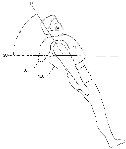
The effectiveness of the present invention may be seen from a comparison of
Figures
J (vltivlu 5luuvvs a ~onvc;Uiunal pt~iur art Iluututiun ~ievicu IOA) with the
1~igure 4
which shows the present invention floatation device 10 in operation. As is
apparent
the user 24 A stabilizes with the axis of the body as indicated by the axis 26
at and
angle a to the surface 28 of the water of about 0° to 4~°
degrees. Whereas the axis 26
of the user 24 of the present invention stabilizes with its axis 26 at and
angle (3 to the
3
CA 02485041 2004-10-19
surface 28 of the water of about 45° to 90° degrees. It is
apparent that the angle a is
considerably smaller than angle (3. 1t is also apparent that the present
invention
(floatation device 10 in Figure 4) holds the user significantly higher above
the water
level. This reorientation and raising of the user 24 higher above the water
level 28 is
primarily due to the effects of side or lateral buoyancy areas 14A and 16A
which as is
clearly apparent in use extend under the arms of the user and have a portion
at the
back of the user (see Figures any of 2a, 2b, 4 and 8) and to a lesser degree
by the rear
buoyancy area 12A. By making the rear buoyancy area 12A so that it extends
farther
down the back of the user 24 than the conventional collar structure of the
prior art
device 10 (Figure 3) the user is forced into the more upright position shown
in Figure
4.
Turning to Figures 5, 6 7 and 8 the construction of the device 10 is more
folly
illustrated and a suitable system for applying the device 10 of the present
invention to
a user is shown.
As shown in Figure 5 the outside of the garment structure into which the
present
invention is incorporated to form the flotation device 10 which preferably is
in the
form of an inflatable bladder 100 (which has essentially the same shape as the
device
10 described above) having a peripheral seam 102 and providing buoyant areas
104,
106, 108, 110 and 112 essentially the same as the portions 12, 14, 16, l8and
20
described above with respect to the schematic illustration s of Figures 1, 2A,
2B, 2C
and 4).
Each of the front areas 110 and I i 2 is provided on its outer surface with a
front
securing strap I 14 that forms a first connecting means for securing its front
area 110
or I 12 to a belt or other means I 16 provided to secure the position of the
device 100
(See figure 7 and 8) relative to the user 24. The waist encircling belt or
strap I 16 of
this arrangement is provided with a buckle or the like 115 as a means of
adjusting its
length
A second connecting means 118 extends as a rear strap or the like 116 (See
figure 5)
from the rear buoyancy area 104 for securing its rear area 104 to the belt or
the like
114 and secure the rear area 104 in position relative to the user 24.
A third connecting means in the form of chest straps is provided on the front
of the
front areas i 10 and 1 12 is formed by a pair of inter engaging elements or
straps 120
4
CA 02485041 2004-10-19
and 122 which when coupled together hold the adjacent edges 124 and 126 of the
front areas I 10 and 112 respectively in close proximity to each other.
To facilitate use and make the garment more comfortable when in use a neck
receiving opening 128 is formed adjacent to the top of the front areas 110 and
112 and
the top of the back floatation area 104.
When the device is inflatable it will normally be provided with a carbon
dioxide (CO
2) inflation mechanism I25 or the like and/or an inflation tube 127 that
permits
inflation by mouth in the event of failure of the CO 2 inflation mechanism
125.
A fourth connecting system is provide by a pair of side straps 130 and 132
located on
the rear area symmetrically positioned on opposite sides of and space below
the
opening 128 (See Figures 6 and 8). These straps 130 and 132 cooperate with
suitable
releasable holding elements e.g. hook and loop fasteners on the straps 130 and
132
and the side areas106 and 108 to secure the side areas 106 and 108 in position
relative to the rear area 104 and the remainder of the floatation device 100.
Because the side areas 106 and 108 are only connected behind the neck, a
single size
floatation device 100 can readily be adjusted to fit a wide range of torso
circumferences.
Having described the invention, modifications will be evident to those skilled
in the
art without departing from the scope of the invention as defined in the
appended
claims.
5