Note: Descriptions are shown in the official language in which they were submitted.
CA 02485300 2004-11-08
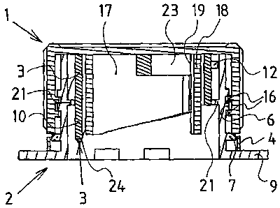
A self-opener closure for composite packagings or for container
spouts to be closed with film material
[0001] The present invention relates to a self-opener closure for composite
packagings as well as to container spouts or bottle spouts of all types to be
closed
with film material. At the same time one specifically envisages liquid
packagings in
the form of such composite packagings of film-coated paper in which, for
example,
milk, fruit juices, all types of non-alcoholic beverages or generally liquids
also in the
non-food range are packaged. The closure may however also be applied to
composite packagings in which goods capable of being poured such as sugar,
semolina or all types of chemicals and likewise are kept or packaged. With
this film-
coated paper it is the case of a laminate material such as a paper or
cardboard web
coated with plastic such as, for example, polyethylene and/or aluminium.
Usually the
volumes of such packagings range from 20 cl up to 2 litres and more.
Alternatively
the self-opener closure may also be assembled on containers which are closed
by
film material, such as on all types of bottles made of glass or plastic or on
similar
containers. Such closures of plastic are known in various embodiments. If they
are
envisaged for a composite packaging, they essentially form a pour-out or
discharge
spout having a rim which radially projects from its lower edge and which forms
a
closing flange at this discharge spout. The spout is equipped with an outer
thread
onto which a rotary cap may be screwed as a closure. Such a self-opener
closure is
flanged onto the composite packaging in that it is sealingly welded onto the
composite packaging with the lower side of its projecting edge, thus with the
lower
side of its flange. However, the free passage at the lower end of the spout is
thereafter closed by paper and sealing film of the composite packaging. In the
case
of a bottle closure the pour-out spout for its part may be placed or screwed
onto the
opening of the bottle, and on its inner side is closed with a film membrane.
The spout
is equipped with an outer thread onto which the rotary cap may be screwed as a
closure. To open, the film-reinforced paper passing through and below the
welded-on
spout, or the film membrane extending within the spout must be cut open or
torn
CA 02485300 2004-11-08
2
open towards the opening or pressed away so that the passage may be cleared
and
the fluid or the pourable material may be poured or shaken out of the
container
through the spout. For this a sleeve or a nipple is arranged within the spout
which, on
rotating the screwed-on cap, is caught by this and thus is rotated by this in
the same
direction of rotation. By means of a thread counter-rotating to the thread on
the outer
side of the spout and on the outer side of the sleeve, this sleeve moves
continuously
in a downward direction on screwing off the rotary cap, that is to say when
said
sleeve is displaced upwards with respect to the liquid packaging. The lower
rim of the
sleeve is provided with one or more tearing or cutting teeth. In this way, and
as a
result of its rotation and constant downwards movement, the sleeve is to press
or cut
a disk out of the film-reinforced paper or film membrane which runs beneath
it.
[0002] However, such conventional self-opener closures do not function
satisfactorily. The disks are not cut cleanly from the paper film or the film
membrane,
but rather the sleeves simply press a piece of film out of this. The remaining
edge is
frayed and thus shreds of paper or film project into the passage which was
supposed
to be cleared. These shreds often project downwards into the container and on
pouring or shaking out possibly block the path of the air flowing from outside
into the
container, or the even project into the path of the outflowing jet of liquid
or the poured
product. With larger packagings having stronger film-reinforced paper or
cardboard
the opening procedure is carried out even less reliably and cleanly. The
sleeve
moving slowly downwards and rotating at the same time, with its complete lower
edge quasi simultaneously contacts the film-reinforced paper web which is to
be cut
open and as a whole presses it downwards and rotates on it until a hole is
scraped
open or broken through rather than cleanly cut open. One problem lies in the
fact that
the film to be cut open gives way slightly to the pressure of the sleeve
acting to a
certain extent as a drill bit, and thus the sleeve no longer acts on a paper
film which
is plane but on one which is curved downwards. Furthermore, the previous
solutions
demand a significant force on the part of the user as a result of the design
of the
sleeves, which are aptly also called penetrators, because indeed they
penetrate a
piece of paper film rather than cleanly cutting a circular disk out of it.
That is to say, a
large torque must be exerted since the teeth or tearers on the lower
penetrator edge
or sleeve edge firstly merely scratch the film and then they must overcome a
large
resistance to rotation. In the uppermost layer of the paper thickness they act
similarly
CA 02485300 2004-11-08
3
to tear-open teeth, specifically in a scraping, pressing and tearing manner,
rather
than acting as actual cutting blades. In order to facilitate the breaking out
or tearing
out for conventional self-opener closures of this type, the film material or
the
composite material is pre-weakened at the desired tear locations by means of
lasers
or punching tools. However, this pre-weakening entails much technological
effort.
Expensive installations are required and the handling for the machining of the
penetration locations on the films is time-consuming. In spite of these
elaborate
weakening measures, the conventional self-opener closures do not cut cleanly,
but
tear the paper or plastic film rather than cleanly cutting it open, which
explains the
large resistance to rotation. On account of these large rotation resistances,
even
breakages of the means which should effect the transmission of the torque from
the
threaded cap to the penetrator sleeve occur, or the catching cams provided to
engage into grooves on the penetrator sleeve can jump out of these grooves. If
this
happens, the self-opener closure is no longer capable of functioning.
[0003] It is therefore an object of the present invention to solve these
problems and
to provide a self-opener closure for composite packagings or for container
spouts
sealed with film material, which reliably permits to cut-out the laminate disk
or film
disk in various dimensions in the clear spout passage and to obtain cleanly
cut edges
so that shreds projecting into the passage are avoided. For a multitude of
film
materials and composite materials it should even be possible to dispense with
the
targeted pre-weakening of the cutting locations by punching or laser
treatment.
[0004] This object is achieved by a self-opener closure for composite
packagings as
well as for container spouts closed with film material, consisting of a spout
which may
be sealingly fitted onto a composite packaging or onto a container closed with
film
material, of an associated rotary cap, as well as of a self-opener arranged
within the
spout and which self-opener may be brought into rotation by the rotary cap.
The self-
opener closure is characterised in that the inner side of the spout is
provided with at
least two guide webs being arranged around its inner circumference and having
varying inclines, so that the sleeve-shaped self-opener, at whose outer side
there are
arranged at least two guide ribs each having a guide surface, and when
continuously
rotating within the spout guiding its guide surfaces at the guide webs,
initially follows
AMENDED
SHEET
CA 02485300 2010-05-12
4
a downwardly directed movement along a steep screw-path which hereafter goes
over into a pure horizontal rotational movement.
According to an aspect of the present invention there is provided a self-
opener closure for composite packagings for container spouts with a film
material, the self-opener closure comprising-
a spout mounted on a composite packaging or on a container spout sealed with
a film material, said spout having an inner side with at least two guide webs
around its inner circumference and having varying inclines;
a rotary cap having an inner side with at least two detached cylinder wall
segments spaced apart from one another in a circumferential direction; and,
a self-opener having a sleeve-shape with said rotary cap and said self-opener
being arranged within said spout and being rotatable via said rotary cap, said
self-opener having an outer side with at least two guide ribs on said outer
side
with each guide rib of said at least two guide ribs of said self-opener having
a
guide surface, so that when said self-opener rotates within said spout, said
guide
surfaces of said self-opener are guided by said at least two guide webs of
said
spout, thereby rotating said self-opener in a downwardly-directed movement
along a screw-path, said self-opener further comprising at an inner side of an
upper edge at least one web extending radially from a sleeve axis and
traversing
a diameter of said self-opener, said at least one web fitting between spaces
of
said at least two detached cylinder wall segments and walls of said spout,
with
said at least two guide ribs of said self-opener being arranged in
distribution over
a circumference of said outer side of said self-opener, said at least two
guide ribs
cooperating with said at least two guide webs at said inner side of said spout
in
distribution over a circumference of said inner side of said spout, so that
when
said rotary cap rotates, torque of said rotary cap transmits over lateral
limiting
edges of said cylinder wall segments to a traversing web and to said self-
opener,
said at least two guide ribs being formed so that, when rotated, said self-
opener
initially follows a steep downwardly-directed screwline movement and
subsequently assumes a purely rotational movement in a horizontal plane.
CA 02485300 2010-05-12
4a
According to another aspect of the present invention there is provided a
self-opener closure for composite packagings for container spouts with a film
material, said self-opener closure comprising-
a spout mounted on a composite packaging or on a container spout sealed with
a film material, said spout having an inner side with at least two guide webs
around its inner circumference and having varying inclines;
a rotary cap having an inner side comprising two detached cylinder wall
segments spaced apart from one another in a circumferential direction; and,
a self-opener having a sleeve-shape with said rotary cap and said self-opener
being arranged within said spout and being rotatable via said rotary cap, said
self-opener having an outer side with at least two guide ribs on said outer
side
with each guide rib of said at least two guide ribs of said self-opener having
a
guide surface, so that when said self-opener rotates within said spout, said
guide
surfaces of said self-opener are guided by said at least two guide webs of
said
spout, thereby rotating said spout in a downwardly-directed movement along a
screw-path, said self-opener having an inner side comprising at least one
traversing web at an upper edge of said self-opener, said at least one
traversing
web fitting between spaces of said two detached cylinder wall segments at said
rotary cap, with a wall of said self-opener being between said two detached
cylinder wall segments and walls of said spout, said outer side of said self-
opener comprising said at least two guide ribs arranged in distribution over a
circumference of said self-opener, said at least two guide ribs interacting
with
said at least two guide webs arranged on said inner side of said spout in
distribution over a circumference of said inner side of said spout, so that
when
said rotary cap rotates, torque from said rotary cap transmits over lateral
limiting
edges of said two detached cylinder wall segments to said traversing web and
to
said self-opener with said at least two guide webs and said spout being formed
so that, when rotated, said self-opener initially follows a steep downwardly-
directed screw-line and subsequently assumes a purely rotational movement in a
horizontal plane.
CA 02485300 2010-05-12
4b
According to a further aspect of the present invention there is provided a
self-opener closure for composite packagings for container spouts with a film
material, said self-opener closure comprising:
a spout mounted on a composite packaging or on a container spout sealed with
a film material, said spout having an inner side with at least two guide webs
around its inner circumference and having varying inclines;
a rotary cap having a cap lid with three free-standing cylinder wall segments
at
an inner side of said cap lid, said three free-standing cylinder wall segments
being spaced apart from one another in a circumferential direction; and,
a self-opener having a sleeve-shape with said rotary cap and said self-opener
being arranged within said spout and being rotatable via said rotary cap, said
self-opener having an outer side with at least two guide ribs on said outer
side
with each guide rib of said at least two guide ribs of said self-opener having
a
guide surface, so that when said self-opener rotates within said spout, said
guide
surfaces of said self-opener are guided by said at least two guide webs of
said
spout, thereby rotating said spout in a downwardly-directed movement along a
screw-path, said self-opener having at an upper edge of an inner side, a star-
shaped web having three webs extending radially from a sleeve axis of said
self-
opener and fitting between spaces of said three free-standing cylinder wall
segments, with a sleeve wall of said self-opener being arranged between said
three free-standing cylinder wall segments and a wall of said spout, said
outer
side of said self-opener comprising said at least two guide ribs arranged in
distribution over a circumference of said self-opener, said at least two guide
ribs
interacting with said at least two guide webs arranged on said inner side of
said
spout in distribution over a circumference of said inner side of said spout,
so that
when said rotary cap rotates, torque from said rotary cap transmits over
lateral
limiting edges of said three free-standing cylinder wall segments to said
traversing web and to said self-opener with said at least two guide webs and
said
spout being formed so that, when rotated, said self-opener initially follows a
steep downwardly-directed screwline and subsequently assumes a purely
rotational movement in a horizontal plane.
CA 02485300 2010-05-12
4c
[0005] The Figures show various views of a preferred embodiment of this self-
opener
closure for composite packagings. By means of these Figures the self-opener
closure
shall be described in detail and its function shall be explained. There are
shown in:
Figure 1 the self-opener closure with its three components in a dismantled
state, in
a side view;
Figure 2 the self-opener closure with its three components in a dismantled
state, in
a side view, whereby all components are shown in a longitudinal sectional
view along the centerline of the closure;
Figure 3 the self-opener closure with its three components in an assembled
state in
a longitudinal sectional view along the centerline of the closure;
Figure 4 the self-opener closure in an assembled state in a perspective view
as
seen from below at an angle, whereby the self-opener sleeve is in its initial
state;
Figure 5 the self-opener closure in an assembled state in a perspective view
as
seen from below at an angle, whereby the self-opener sleeve is in an
extended or lowered state ready for the cutting movement;
Figure 6 the self-opener closure in an assembled state in a perspective view
as
seen from below at an angle, whereby the self-opener sleeve is shown to
be completely removed from the spout; and
Figure 7 the self-opener closure in an embodiment for assembling on a
container
closed with a film.
[0006] Figure 1 shows the self-opener closure in a dismantled state. It
consists of
three components made of injection moulded plastic, namely a rotary cap 1, a
CA 02485300 2004-11-08
discharge spout 2 and a self-opener sleeve 3. The rotary cap 1 is provided on
its
outer surface with knurls or grooves for ease of handling. A guarantee strip 4
is
injection moulded to the lower edge of the rotary cap 1 and is connected to
the rotary
cap 1 only by thin material bridges or bars 5 being designed as and arranged
to be
5 predetermined breaking points. At its outer side the discharge spout 2 is
provided
with an outer thread which fits to an equivalent inner thread on the rotary
cap 1,
whereby this is not visible here. Beneath the outer thread 6 the spout 2 has a
small,
obliquely angled bead 7 with an angular or square-edged rim 8 on its lower
side.
Alternatively, instead of a discharge spout 2 having an outer thread and an
appropriate threaded cap having an inner thread, a discharge spout having an
appropriate cap can be foreseen, whereby the rotary cap can be mounted onto
the
discharge spout by means of a bayonet coupling. For this, the spout is
provided on
its outer side with appropriate grooves and the rotary cap is provided on its
inner side
with equivalent cams, or vice versa. The counter-clockwise rotation of the
rotary cap,
which is to be carried out initially in a horizontal plane, firstly activates
the self-opener
sleeve exactly in the same way as usually the threaded cap is activated, which
shall
be more closely described hereinafter. A radially projecting, annular and
planar
projection or brim 9 is formed at the lower edge or rim of the spout 2. With
the lower
surface of this planar projection, the spout 2 is sealingly welded onto a
composite
packaging made of a laminate composed of a film-reinforced paper or cardboard
web. Therefore, this laminate extends continuously beneath the discharge spout
2
and, on its underside, seals the clear passage opening of the spout 2. In
order to be
able to pour liquid through this spout out of the packaging, the laminate in
the region
of the passage opening must be pressed away, perforated, cut away or torn
away. It
is desirable to uncover the passage opening as completely as possible, which
means
that the laminate in this area is cut away as cleanly as possible, after which
the cut
laminate disk can be pivoted away, thus clearing the passage as completely as
possible. A self-opener in the form of a specially formed sleeve 3 serves to
uncover
the passage opening. At the lower edge of this sleeve 3 there is provided at
least one
lancing mandrel 10 having a sharp tip 24, which, when viewed from above onto
the
sleeve 3, forms a sharp cutting edge 11 in a counter-clockwise direction. At
the outer
circumference of the self-opener sleeve 3 there are provided at least two
guide ribs
12 distributed over the circumference, and preferably, as shown in the
embodiment,
four guide ribs are provided. Each of these guide ribs 12 is composed of two
sections
CA 02485300 2004-11-08
6
13, 14, namely a section 13 extending horizontally at the sleeve 3 and a
vertical
section 14, which together form a right angle. The outer tip of this right
angle is
bevelled at an angle of 450 to the sections 13, 14 and this bevelled surface
forms a
guide surface 15, which is intended to glide along a guide curve formed of
guide
webs at the inner wall of the spout 2, as shall be more clearly shown in
further
Figures.
[0007] In Figure 2 there is shown the self-opener closure also with its three
components, that is to say the rotary cap 1, the discharge spout 2 and the
self-
opener sleeve 3 in a dismantled state. However, all components are shown in a
longitudinal section along the centreline of the closure. Inside the rotary
cap 1 the
inner thread 16 can be seen. At the lower edge, the guarantee strip 4 is seen
attached by several thin material bridges or bars 5 serving as predetermined
breaking points. As a feature, within this rotary cap 1 at the underside of
the cap lid in
the shown embodiment, there are formed two cylinder wall segments 17, 18,
whereas the radius of the corresponding cylinder is smaller than that of the
cylindrically shaped rotary cap wall. Both cylinder wall segments 17, 18,
which follow
each other in the circumferential direction, are spaced from each other by a
small
lateral space, so that a slit 19 is formed between each of them. The lower
edges of
the two cylinder wall segments 17, 18 are designed to slope downwards and thus
each form a lower edge leading downwardly directed in a screwline shape. At
the
discharge spout 2 shown beneath the rotary cap 1, guide webs 20 are arranged
in
distribution over the inner circumferential wall of the spout 2, which guide
webs are to
cooperate or interact with the guide ribs 12 of the self-opener sleeve 3. In
the
embodiment shown there are four such guide webs 20; one is shown in full, the
two
on the left and the right of the Figure are shown each in half, and the one
arranged at
the portion of the spout 2 which has been cut away for this illustration is
not visible at
all. Each of these guide webs 20 consists of a horizontal section 21 and a
section 22
which inclines or slants upwards towards the axis of the spout. At the outer
side of
the spout 2 the grooves of the outer thread 6 and the bead 7 can be seen, over
which
the rotary cap 1, for assembling with its guarantee strip 4, can be
irreversibly drawn
or pushed. Because the upper side of the bead 7 is inclined, the guarantee
strip 4
can be pushed down over this bead 7 under slight deformation. In contrast, and
because of the sharp edge or rim 8 at the lower side of the bead 7, the
guarantee
CA 02485300 2004-11-08
7
strip 4 cannot be pulled back upwards over the bead 7 once it has tightly
enclosed
the circumferential wall of the spout 2 below this bead. Therefore, in order
to open
the rotary cap 1, the guarantee strip 4 must be removed by tearing it away,
thus
rupturing the material bridges 5. This releases the rotary cap 1 to be turned
and
moved upwards. The projection 9 projecting radially from the lower rim of the
spout 2
is welded to the paper laminate or cardboard laminate of a packaging for
liquids or
dry goods by means of ultrasonic welding. The self-opener sleeve 3 is shown
beneath the spout 2. The lower edge of the sleeve 3 tapers off in a guide
mandrel 10,
which, when viewed from above towards the side in counter-clockwise direction,
forms a sharp cutting edge 11 and tapers off at the end in a sharp tip 24. To
the right
of Figure 2 one sees the horizontally extending section 13 of an individual
guide rib
12 at the outer wall of the sleeve 3. At the inner side close to the upper
edge of the
self-opener sleeve 3 a web or bridge 23 traverses the clear distance of the
sleeve 3.
When the components of this self-opener closure are assembled, the self-opener
sleeve 3 is arranged within the spout 2. In doing so, the sleeve 3 is
rotationally
pushed into the spout 2 in such a manner that the guide ribs 12 of its
bevelled guide
surface 15 come to rest at the underside of the upper end of the inclined or
slanting
section 22 of the guide webs 20 at the spout 2. In turn, the rotary cap 1 is
mounted in
such a rotational position onto these two components that the traversing web
23 is
arranged in the slits 19 between the two cylinder wall segments 17, 18 at the
lower
lid side of the rotary cap 1. Under slight deformation of its guarantee strip
4, the
rotary cap 1 is pushed with force over the upper taper of the bead 7 and thus
secures
the rotary cap 1 from twisting by subsequently closely fitting to the outer
side of the
spout wall, because it is retained in its lowest screw position by the
guarantee band 4
and can only be unscrewed if the guarantee band 4 is first torn away, because
this
can no longer glide over the sharp lower edge 8 of the bead 7.
[0008] Figure 3 shows the self-opener closure with its three components in an
assembled state in a longitudinal section along the centreline of the closure.
One
sees that the self-opener closure 3 lies between the cylinder wall segments
17, 18
and the spout 2, and that the traversing web 23 extends at the upper edge of
the
sleeve 3 in the slit 19 between the neighbouring cylinder wall segments 17,
18. At the
outer side of the sleeve 3 one sees the horizontal section 13 of one of its
guide ribs
12. On the inner side of the spout 2 one sees the horizontal sections 21 of
the guide
CA 02485300 2004-11-08
8
webs 20, and at the outer side of the spout 2 the ribs of the outer thread 6
and, a little
further down, the bead 7 over which the guarantee band 4 is pushed, as well as
the
radial projection 9 at the lower edge or rim of the spout 2. At the inner side
of the
rotary cap 1 its inner thread 16 can be seen, and at the lower edge of the
rotary cap
1 the guarantee band 4 connected by fine material bridges 5. In this
embodiment, the
self-opener closure 3 is in its initial state, that means it is completely
drawn back into
the rotary cap 1.
[0009] There now follows a description of how the components 1, 2 and 3 of
this self-
opener closure interact when opening the closure and thereby cutting open the
paper
or cardboard laminate which is welded onto the spout 2. Firstly, the guarantee
band 4
is torn away. This releases the rotary cap 1 for unscrewing in that it can
move
upwards along the spout 2. The lateral limiting surfaces of the cylinder wall
segments
17 and 18 now act upon the traversing web 23 at the self-opener closure, that
means
they entrain it and thus cause it to rotate in the direction of unscrewing the
rotary cap
1 when viewed from above, that means in a counter-clockwise direction. In an
alternative embodiment, instead of a single traversing web there can be
provided a
star-shaped web having three arms or webs distributed radially around the
circumference from the center of the sleeve 3 and projecting outwards; in this
case,
suitable cylinder wall segments must be foreseen, between which the three webs
come to lie. Also four radial webs which together form a cross made of two
webs
traversing the sleeve diameter are possible, whereas then four cylinder wall
segments are distributed around the circumference. When the sleeve 3 now is
brought into rotation in a counter-clockwise direction via its web 23, then
the guide
surfaces 15 of its guide ribs 12, as seen in Figures 1 and 2 but not visible
here, glide
along the underside of the guide webs 20 in a downward direction at the spout
2.
Rotation of the rotary cap 1 to the left is thus accompanied by a steep,
screwline
downwardly directed movement of the self-opener closure 3. As a result of this
steep
downward movement, the paper or cardboard laminate which extends over the
clear
breadth of the spout 2 is initially essentially perforated or pierced by the
sharp tip 24
of the lancing mandrel at the tower edge of the sleeve 3. Thus, only a hole is
pierced
into the edge of the laminate disk, that means that the laminate is pierced
and not
cut. Seen microscopically, when pierced the laminate material is displaced to
all
sides and is torn at the piercing point. The reaction forces of the piercing
movement
CA 02485300 2004-11-08
9
are brought about via the welding by the projecting brim 9 of the spout 2.
This first
movement step of the self-opener closure is decisive. Due to the fact that in
conventional solutions the self-opener sleeve continuously rotates downwardly
directed in a screwline and its teeth thus impinge upon the film at a flat
angle, they
are not able to pierce the film. However, with the present solution, in a
first phase the
sleeve experiences a very steep downwardly directed movement. The sharp tip 24
of
its lancing mandrel 10 thus impinges on the film at a steep angle and pierces
it
initially virtually locally. By the time the paper or cardboard or plastic
film has been
pierced, the sleeve 3 has reached its lowest position in relation to the spout
2, that
means that the guide surface 15 at its guide ribs 12 is now positioned at the
end of
the inclined guide webs 22 at the inner wall of the spout, or at the beginning
of the
horizontal sections 21 of the guide webs. If the rotary cap 1 is further
turned in a
counter-clockwise direction, then also the sleeve 3 is turned further in a
counter-
clockwise direction but no longer moves downwards, but rotates in a horizontal
plane. Now the lancing mandrel 10 protruding through the paper or cardboard
film
acts as a knife with its sharp cutting edge 11. Thus the cutting edge 11 cuts
out a
circular disk out of the paper or cardboard laminate along the lower inner
edge of the
spout 2. The cutting movements extend over one rotation of the sleeve of about
340 .
At the finish of the cutting rotation, the cut out disk is suspended merely by
a thin
material bridge and, by means of the pressure force of the cutting edge 11
acting in
the cutting direction, is pivoted or is folded downwards into the packaging
and is
retained in this downwardly pivoted position. Thus, in principle, this self-
opener
closure functions like a classic can opener. Also when opening a can it is
decisive
that the lid is first pierced by an essentially vertical movement of the tip
of the cutting
tool upon and through the can lid. Only when the can lid has been pierced by
the tip
of the cutting tool does there follow a separate, now horizontally directed
cutting
movement of the cutting tool. The present self-opener closure achieves
precisely this
can-opener effect, in that the sleeve moves first of all steeply downwards and
in a
first phase merely pierces the film with the tip 24 of the lancing mandrel 10,
and
thereafter in a second phase, the lancing mandrel 10 with its cutting edge 11
acts as
a cutting tool in that the sleeve is rotated horizontally. Therefore, an
essential feature
is that the movement of the sleeve is discontinous or erratic. After a steep
downwardly directed movement for piercing the film there follows a
discontinuous
point and then a horizontal rotational movement for cutting. Piercing and
cutting are
CA 02485300 2004-11-08
distinctly different, such as in opening a metal can with a can opener. At the
lower
edge of the inner side of the spout 2 there is a recess 25 which is bordered
or framed
by ramps 26. During the end phase of the rotational movement of the sleeve 3,
a
horizontal section 21 enables one of its guide ribs 2 to glide over the ramp
26 and
5 engage into this recess 25. Thereafter the sleeve 3 can be neither rotated
further
forwards nor backwards, so that after cutting out and pivoting away of the
laminate
disk, the sleeve is held in this position. In this manner the laminate disk
which has
been almost totally cut away is reliably retained pivoted downwards in the
liquid
packaging. Until the entire cutting movement, that is the rotation of the
sleeve 3
10 about 3400 after piercing of the paper or cardboard laminate, has been
completed,
the rotary cap I at the spout 2 is screwed upwards for such a distance that
the
cylinder wall segments 17, 18 projecting downwards at the underside of the
rotary
cap lid are lifted over the web 23 at the sleeve 3 and thus cannot transmit
any torque
to the web 23. Thereafter, the rotary cap I is completely unscrewed from the
spout 2
and the liquid can now exit the liquid packaging via the uncovered spout 2 or,
in the
case of dry goods, can be poured out through the spout 2. Now the rotary cap I
can
again be screwed onto the spout 2 to re-seal the closure. When the rotary cap
1 is
again screwed on to close the closure, the screwline shaped, downwards
extending
lower edges of the cylinder wall segments 17, 18 effect that no torque in a
clockwise
direction is transmitted to the web 23, in that these screwline shaped lower
edges
merely glide over the upper side of the traversing web 23, but can no longer
entrain
it.
(0010] Figures 4 and 5 illustrate the mode of operation of this self-opener
closure
particularly well. Figure 4 shows the self-opener closure in an assembled
state in a
perspective view as seen from below at an angle. The self-opener closure 3 is
in its
initial state. At its upper edge one sees a portion of the traversing web 23
which
connects its upper edge at two points. This web 23 lies between the two
cylinder wall
segments 17, 18 which are moulded to the underside of the lid of the rotary
cap 1.
When the rotary cap 1 is rotated in a loosening direction, in this case as
seen from
below in a clockwise direction, then the cylinder wall segments 17, 18 entrain
the
web 23 lying there between and thus also the sleeve 3, and, due to the special
guide
ribs 12 at its outer side and the guide webs 20 at the inner side of the
spout,
compelling the sleeve to be moved in a downward direction in a steep spiral.
In doing
CA 02485300 2004-11-08
11
so, the sharp tip 24 of the lancing mandrel 10 acts as a piercing tip and
first pierces
the paper or cardboard laminate welded onto the underside of the projecting
brim 9
of the spout 2 of the composite packaging.
[0011] In Figure 5 there is shown the self-opener closure with the self-opener
sleeve
in an extended or completely lowered state. Having reached this position, the
sleeve
3 may rotate further only in a horizontal plane, whereby the lancing mandrel
10 now
acts as a knife, because its edge, here seen from below and oriented in a
clockwise
direction, is formed as a sharp cutting edge 11. When the rotary cap 1 is
further
rotated by 340 , this cutting edge moves along the lower inner edge of the
spout 2,
thereby cutting a circular disk out of the paper or cardboard laminate which
is welded
to the underside of the projection 9, but is not shown here. As soon as the
sleeve 3
has completed a rotation about 340 after having pierced the paper laminate,
the end
of one of the horizontal sections 13 of its guide ribs 12 engages in the
recess 25 at
the inner wall of the spout 2 and prevents the sleeve 3 from being able to be
rotated
further forwards or reversely. In this position the sleeve 3 has almost
completely
pivoted the disk which was cut away from the laminate downwards into the
container
and securely retains it in this position. The discharge through the spout 2 is
thus
enabled.
[0012] Figure 6 shows the discharge spout 2 and the sleeve 3 of the self-
opener
closure in an assembled state in a perspective view as seen from below at an
angle,
whereby the self-opener sleeve 3 is shown to be completely disengaged from the
spout 2, so that the special arrangement of its guide ribs 12 can be seen more
clearly
and thus its function can be better understood.
[0013] Figure 7 shows an alternative embodiment of this self-opener closure
for
assembling on a membrane sealed neck of a container or a bottle. Therefore,
the
discharge spout 2 is not provided with a projecting rim at its underside, but
is
arranged over a shoulder 27 in a thread sleeve 28, which can be screwed on to
the
outer thread of a bottleneck or to the discharge spout of any type of
container which
is closed or sealed at its upper rim with a film.
CA 02485300 2010-05-12
List of reference numerals 12
1 rotary cap
2 discharge spout
3 self-opener sleeve
4 guarantee strip
5 material bridge, bar
6 outer thread
7 bead
8 angular, square-edge rim
9 projection, brim
10 guide mandrel, lancing mandrel
11 cutting edge
12 guide ribs
13 (horizontal) section
14 (vertical) section
15 guide surface
16 inner thread
17 cylinder wall segment
18 cylinder wall segment
19 slit
20 guide webs
21 horizontal section
22 (inclined / slanting) guide webs
23 traversing web
24 sharp tip
25 recess
26 ramp
27 shoulder
28 thread sleeve