Language selection

Search

Patent 2485454 Summary

Third-party information liability

Some of the information on this Web page has been provided by external sources. The Government of Canada is not responsible for the accuracy, reliability or currency of the information supplied by external sources. Users wishing to rely upon this information should consult directly with the source of the information. Content provided by external sources is not subject to official languages, privacy and accessibility requirements.

Claims and Abstract availability

Any discrepancies in the text and image of the Claims and Abstract are due to differing posting times. Text of the Claims and Abstract are posted:

  • At the time the application is open to public inspection;
  • At the time of issue of the patent (grant).
(12) Patent: (11) CA 2485454
(54) English Title: ANNULAR CO-EXTRUSION DIE
(54) French Title: FILIERE POUR CO-EXTRUSION ANNULAIRE
Status: Expired and beyond the Period of Reversal
Bibliographic Data
(51) International Patent Classification (IPC):
  • B29C 48/16 (2019.01)
  • B29C 48/30 (2019.01)
(72) Inventors :
  • PLANETA, MIREK (Canada)
  • SAGAR, SURENDRA M. (Canada)
(73) Owners :
  • MACRO ENGINEERING & TECHNOLOGY INC.
(71) Applicants :
  • MACRO ENGINEERING & TECHNOLOGY INC. (Canada)
(74) Agent: GOWLING WLG (CANADA) LLP
(74) Associate agent:
(45) Issued: 2010-11-23
(22) Filed Date: 2004-10-20
(41) Open to Public Inspection: 2005-06-01
Examination requested: 2008-02-28
Availability of licence: N/A
Dedicated to the Public: N/A
(25) Language of filing: English

Patent Cooperation Treaty (PCT): No

(30) Application Priority Data:
Application No. Country/Territory Date
10/724197 (United States of America) 2003-12-01

Abstracts

English Abstract


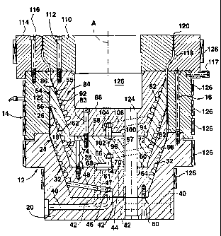
An annular co-extrusion die for extruding multi-layer tubular plastic film has
inner die
members stacked one upon another, with respective radially outwardly extending
helical
passages defined between respective pairs of inner die members. An annular
outer die
member surrounds the stacked inner die members and forms a longitudinally
extending
annular passage therebetween for conveying plastic material from the helical
passages to
an annular extrusion orifice. Feed passages in the inner die members carry
plastic
materials to the respective helical passages, so that each helical passage can
provide a
layer in a multi-layer plastic film extruded into the annular passage and from
the annular
extrusion orifice.


French Abstract

Filière pour co-extrusion annulaire visant à extruder le film plastique tubulaire à plusieurs couches et comportant des filières superposées les unes sur les autres, avec des canaux hélicoïdaux respectifs s'étendant sur le radial et définis entre les paires respectives des filières intérieures. Une filière annulaire extérieure entoure les filières intérieures superposées et forme un canal annulaire s'étendant longitudinalement entre ces dernières pour transporter le matériel plastique des canaux hélicoïdaux à un orifice d'extrusion annulaire. Les canaux d'alimentation dans la filière intérieure transportent le matériel plastique aux canaux hélicoïdaux respectifs, de sorte que chaque canal hélicoïdal peut fournir une couche de film plastique à plusieurs couches extrudées dans le canal annulaire, à partir de l'orifice d'extrusion annulaire.

Claims

Note: Claims are shown in the official language in which they were submitted.


WE CLAIM:
1. An annular co-extrusion die for extruding multi-layer tubular plastic film,
said die
including:
inner die members stacked one upon another and having radially outwardly
extending
surfaces forming radially outwardly extending helical passages between
respective
pairs of inner die members;
an annular outer die member surrounding said stacked inner die members and
forming a longitudinally extending annular passage therebetween for conveying
plastic material from said radially outwardly extending helical passages to an
annular
extrusion orifice;
a lower inner die member having a first feed passage extending from a lower
surface
thereof to a substantially horizontal upper surface thereof at a position
spaced from a
central longitudinal axis of said longitudinally extending annular passage,
said
substantially horizontal upper surface having a first groove extending from an
upper
end of said first feed passage to said longitudinal axis;
an upper inner die member immediately above said lower inner die member having
a
substantially horizontal lower surface engaged with the substantially
horizontal upper
surface of said lower inner die member, said substantially horizontal lower
surface
having a second groove extending from the upper end of said first feed passage
to
said longitudinal axis and forming a second feed passage with said first
groove;
said upper inner die member having a third feed passage extending
substantially
vertically upwardly from the lower substantially horizontal surface thereof at
said
longitudinal axis and in communication with said second feed passage, and
at least one fourth feed passage in said upper inner die member extending from
an
upper end of said third feed passage to the helical passages between said
upper and
lower inner die members.
-7-

2. An annular co-extrusion die according to claim 1 wherein the radially
outwardly
extending surfaces are inclined to the longitudinal axis of the die at an
angle in the
range of from about 5 to about 90 degrees.
3. An annular co-extrusion die according to claim 1 wherein the inner die
members have
a circumferentially extending series of vertically aligned substantially
vertical
passages for supplying cooling air to the inner side of tubular film extruded
from the
extrusion orifice.
-8-

Description

Note: Descriptions are shown in the official language in which they were submitted.


CA 02485454 2010-06-07
ANNULAR CO-EXTRUSION DIE
FIELD OF INVENTION
[0001] The present invention relates to annular co-extrusion dies for
extruding multi-
layer tubular plastic film.
BACKGROUND OF THE INVENTION
[0002] Many different kinds of multi-layer plastic film are required for
present day
purposes. However, it is not possible to satisfactorily produce such different
kinds of
multi-layer plastic film with one kind of die. For example, the annular co-
extrusion die
described and claimed in U.S. Patent 5,690,972 (Planeta et al.) issued
November 25,
1997, is very useful because such a die is easy to take apart and clean and
also has a
relatively low wetted surface area compared to other dies of similar size.
[0003] However, the die described in the above patent is not as suitable as is
currently
desired for producing multi-layer tubular film which includes at least one
layer of
material which has poor flow characteristics. It is therefore an object ofthis
invention to
provide an annular co-extrusion die which has a similar versatility as the die
described in
the above patent, but which is especially suitable for producing tubular multi-
layer film
with at least one layer of material with poor flow characteristics.
SUMMARY OF THE INVENTION
[0004] According to the invention, an annular co-extrusion die for extruding
multi
layered tubular plastic film has inner die members stacked one upon another
and having
radially outwardly extending surfaces forming radially outwardly helical
passages
between respective pairs of inner die members. An annular outer die member
surround
the stacked inner die members and forms a longitudinally extending annular
passage
therebetween for conveying plastic material from said radially outwardly
extending
helical passages to an annular extrusion orifice. A lower inner die member has
a first
feed passage extending from a lower surface thereof to a substantially
horizontal upper
surface thereof at a position radially spaced from a central longitudinal axis
of the
longitudinally extending annular passage, the substantially horizontal upper
surface
-1-

CA 02485454 2010-06-07
having a first groove extending from the upper end of the first feed passage
to the
longitudinal axis.
[0005] An upper inner die member immediately above the lower inner die member
has a
substantially horizontal lower surface engaged with the substantially
horizontal upper
surface of the lower inner die member, a substantially horizontal lower
surface having a
second groove extending from the upper end of the first feed passage to the
longitudinal
axis and forming a second feed passage with the first groove. The upper inner
die
member has a third feed passage extending substantially vertically upwardly
from the
lower relatively horizontal surface thereof at the longitudinal axis and in
communication
with the second feed passage. At least one fourth feed passage in the upper
inner die
member extends from the upper end of the third feed passage to the helical
passages
between the upper and lower die members.
[0006] The radially outwardly extending surfaces may be inclined to the
longitudinal axis
of the die at an angle in the range from about 5 to about 90 degrees.
[0007] The inner die members may have a circumferentiallly extending series of
vertically aligned substantially vertical passages for supplying cooling air
to the inner side
of tubular film extruded from the extrusion orifice.
BRIEF DESCRIPTION OF THE DRAWINGS
[0008] One embodiment of the invention will now be described, by way of
example, with
reference to the accompanying drawing, of which:
[0009] Fig. 1 is a sectional somewhat diagrammetic view of an annular
extrusion die in
accordance with one embodiment of the invention, with some parts being omitted
for
clarity.
DETAILED DESCRIPTION
[0010] Referring first to Fig. 1 of the drawing, an annular co-extrusion die
has a lower
annular outer die body member 12 and an annular outer die body member 14
mounted on
the lower outer die member 12 and secured thereto by circumferentially spaced
bolts 16
-2-

CA 02485454 2010-06-07
(only one of which is shown). The lower outer die member 12 has a radially
outwardly
and upwardly extending inner surface 18 which extends at an angle of about 20
degrees to
the longitudinal axis A of the die. The lower outer die member 12 also has a
base
portion 20.
[0011 ] A first inner die mandrel 24 has a radially outwardly and upwardly
extending side
wall 26 and a base portion 28. The die mandrel 24 fits snugly into the lower
outer die
member 12. The outer surface of the side wall 26 has a series of helical
grooves 32
which co-operate with the inner surface 18 of the outer die member 12 to form
outwardly
and upwardly extending helical passages therebetween. The helical grooves 32
have
multiple starts (not shown), in the same manner as shown in Fig. 2 of U.S.
Patent
5,690,792.
[0012] The base portion 20 of the lower outer die member 12 has a
circumferentially
extending series of horizontal feed passages 40 extending radially inwardly
from the
exterior of the base portion 20. At its inner end, each feed passage 40 has a
90 degree
bend to a vertical passage portion 42 which opens onto the upper surface 44 of
the base
portion 20. One of the vertical feed passage portions 42 is at the radial
centre of the base
portion 20, i.e. is located on the longitudinal axis A of the die.
[0013] The first inner die mandrel 24 has a vertical feed passage 46 extending
upwardly
for a short distance from its lower surface and aligned with the vertical
portion 32 of the
relevant feed passage 40. The base portion 28 of the first mandrel 24 has a
circumferentially extending series of transverse feed passages 48 extending in
a radially
outwardly and slightly upward manner from the upper end of the vertical feed
passage 46,
each feed passage 48 extending to the lower end of a respective one of the
helical grooves
32. For clarity, only one of the feed passages 48 is shown. The base portion
28 of the
mandrel 24 is bolted to the base portion 20 of the lower outer die member 12
by
circumferentially spaced bolts 50 (only one of which is shown).
[0014] The base portion 28 of the mandrel 24 also has two circumferentially
spaced
vertical feed passages 47 extending from the bottom to the top thereof and
radially spaced
from the longitudinal axis A of the die for a purpose which will be described
later.
-3-

CA 02485454 2010-06-07
[0015] A second mandrel 54 which is identical to the lower mandrel 24 is
mounted on
top of the lower mandrel 24 and is nested therein, i.e. in stacking
relationship therewith.
The second mandrel 54 has a radially outwardly and upwardly extending sidewall
56 and
a base portion 58. The outer surface of side wall 56 has a series of helical
grooves 62
which co-operate with the inner surface 27 of the lower mandrel 24 to form
radially
outwardly and upwardly extending helical passages therebetween. As before, the
helical
grooves 62 have multiple starts (not shown) at their lower ends. One of the
vertical
passage portions 42 of a feed passage 40 is radially spaced from the
longitudinal axis A
of the die (to the left thereof as seen in Fig. 1), and is aligned with one of
the vertical
passages 47 in the base portion 28 of the first mandrel 24.
[0016] The base portion 58 of the mandrel 54 also has a vertical feed passage
57
extending vertically from the bottom to the top thereof and radially spaced
from the
longitudinal axis A of the die and aligned with the other vertical passage 47
in the base
portion 28 of the first mandrel 24, again for a purpose which will be
described later.
[0017] The upper surface 60 of the base portion 28 of the first mandrel 24 has
a groove
61 extending radially inwardly from the upper end of one of the vertical feed
passages 47
to the longitudinal axis A of the die. The lower surface 64 of the base
portion 58 of the
mandrel 54 has a complementary groove 66 forming a horizontal passage 68 with
the
groove 61. At its radially outer end, the horizontal passage 68 communicates
with the top
of the relevant vertical passage 47, and at the longitudinal axis A
communicates with a
short vertical passage 70 in the base portion 58. The base portion 58 also has
a
circumferentially extending series of transverse feed passages 72 (only one of
which is
shown) extending in a radially outwardly and slightly upwardly inclined manner
from the
upper end of the vertical passage 70, each feed passage 72 extending to the
lower end of a
respective one of the helical grooves 62. The second mandrel 54 is bolted to
the first
mandrel 24 by circumferentially spaced bolts 74 (only one of which is shown).
[0018] A further and uppermost die mandrel 84 is mounted on top of the second
mandrel
54 and is nested therein, ie, in stacked relationship therewith. The mandrel
84 has a
radially outwardly and upwardly inclined outer surface 84 and a base portion
88. The
outer surface 86 has a series of helical grooves 92 which co-operate with the
inner surface
55 of side wall 56 to form radially outwardly and upwardly extending helical
passages
-4-

CA 02485454 2010-06-07
therebetween. As before, the helical grooves 92 have multiple starts at their
lower ends.
The base portion 88 of the mandrel 84 is secured to the base portion 58 of the
mandrel 54
by circumferentially spaced bolts 93 (only one of which is shown).
[0019] The upper surface 94 of the base portion 58 of the second mandrel 54
has a
groove 96 extending radially inwardly from the upper end of the passage 57 in
the base
portion 58 of the second mandrel 54 to the longitudinal axis A of the die. The
lower
surface 98 of the base portion 88 of the mandrel 84 has a complementary groove
100
forming a horizontally extending passage 102 with the groove 96. At its
radially outer
end, the horizontal groove 102 communicates with the top of the vertical
passage 57 and
at the longitudinal axis A communicates with a short vertical passage 104 in
the base
portion 88 of mandrel 84. Base portion 88 also has a circumferentially
extending series
of helical feed passages 106 (only one of which is shown) extending in a
radially
outwardly and slightly upward inclined manner from the upper end ofthe
vertical passage
104, each feed passage 106 extending to the lower end of the respective one
ofthe helical
grooves 92.
[0020] An inner annular die lip member 110 is mounted on top of the upper
mandrel 84
and is secured thereto by bolts 112 (only one of which is shown). An outer
annular die
lip member 114 is mounted on the upper outer die member 14 and secured thereto
by
bolts 116, 117 (only one each of which is shown). The die members 110,114 co-
operate
to form an annular extrusion passage 118 and an annular extrusion orifice 120.
[0021] An annular extrusion passage 112 is formed between the outer surfaces
of the
mandrels 24, 54, 84 and the inner surfaces of the outer die member 14. The
annular
extrusion passage 122 extends to the annular extrusion passage 118 formed by
the die lip
members 110, 114. The outer die members 12, 14 and the outer lip member 114
are
provided with separate heaters 126.
[0022] To enable internal bubble cooling to be provided, the base portions 20,
28, 58, 88
of the lower outer die member 12 and the mandrels 24, 54, 84 are provided with
relatively
large aligned circumferentially spaced vertical passages 124 for supplying
cooling air
from the bottom of the die to a central chamber 126 at the top of the die and
provided by
-5-

CA 02485454 2010-06-07
the upper mandrel 84 and inner die lip member 110. The vertical passages 124
extend
between the transverse passages 48, 72, 106.
[0023] In use, different plastic materials are supplied from extruders through
the feed
passages 40. As shown, one of the feed passages 40 supplies plastic material
to the
vertical feed passage 46 and the transverse feed passages 48 to the helical
grooves 32 so
as to extrude a first film layer into the annular passage 122. Another passage
40 feeds
plastic material to the vertical passage 47, horizontal passage 68 and
vertical passage 70
to transverse passages 72 and helical grooves 62 to extrude a second film
layer into the
annular passage 122. A third passage 40 feeds plastic material through the
vertical
passages 47, 57, the horizontal passage 102 and the vertical passage 104 to
the transverse
passages 106 and the helical grooves 92 to extrude a third film layer into the
annular
passage 122. Thus, a three layer plastic film is extruded into the annular
passage 118 and
from the extrusion orifice 120.
[0024] A person skilled in the art will readily appreciate from the foregoing
description
of a preferred embodiment that the present invention reduces the likelihood of
uneven
flow in the die. Also, a die in accordance with the invention provides good
melt
distribution and enables a wide variety of plastic materials with a wide
variety of
viscosities to be processed in the same die. Additionally, of course, a
greater or smaller
number of mandrels and outer die members may be used when the film to be
produced
has more or less than three layers.
[0025] Other embodiments and advantages of the invention will now be readily
apparent
to a person skilled in the art, the scope of the invention being defined in
the appended
claims.
-6-

Representative Drawing
A single figure which represents the drawing illustrating the invention.
Administrative Status

2024-08-01:As part of the Next Generation Patents (NGP) transition, the Canadian Patents Database (CPD) now contains a more detailed Event History, which replicates the Event Log of our new back-office solution.

Please note that "Inactive:" events refers to events no longer in use in our new back-office solution.

For a clearer understanding of the status of the application/patent presented on this page, the site Disclaimer , as well as the definitions for Patent , Event History , Maintenance Fee  and Payment History  should be consulted.

Event History

Description Date
Inactive: IPC deactivated 2021-11-13
Inactive: IPC assigned 2021-03-17
Inactive: First IPC assigned 2021-03-17
Inactive: IPC assigned 2021-03-17
Common Representative Appointed 2019-10-30
Time Limit for Reversal Expired 2019-10-21
Inactive: IPC expired 2019-01-01
Letter Sent 2018-10-22
Change of Address or Method of Correspondence Request Received 2018-01-16
Grant by Issuance 2010-11-23
Inactive: Cover page published 2010-11-22
Pre-grant 2010-09-10
Inactive: Final fee received 2010-09-10
Notice of Allowance is Issued 2010-08-16
Letter Sent 2010-08-16
Inactive: Approved for allowance (AFA) 2010-08-11
Amendment Received - Voluntary Amendment 2010-06-07
Inactive: S.30(2) Rules - Examiner requisition 2009-12-14
Letter Sent 2008-04-22
Request for Examination Received 2008-02-28
Request for Examination Requirements Determined Compliant 2008-02-28
All Requirements for Examination Determined Compliant 2008-02-28
Inactive: IPC from MCD 2006-03-12
Letter Sent 2005-11-28
Inactive: Single transfer 2005-11-01
Application Published (Open to Public Inspection) 2005-06-01
Inactive: Cover page published 2005-05-31
Inactive: First IPC assigned 2005-01-31
Inactive: IPC assigned 2005-01-31
Inactive: Courtesy letter - Evidence 2004-12-21
Inactive: Filing certificate - No RFE (English) 2004-12-15
Filing Requirements Determined Compliant 2004-12-15
Application Received - Regular National 2004-12-15

Abandonment History

There is no abandonment history.

Maintenance Fee

The last payment was received on 2010-07-27

Note : If the full payment has not been received on or before the date indicated, a further fee may be required which may be one of the following

  • the reinstatement fee;
  • the late payment fee; or
  • additional fee to reverse deemed expiry.

Patent fees are adjusted on the 1st of January every year. The amounts above are the current amounts if received by December 31 of the current year.
Please refer to the CIPO Patent Fees web page to see all current fee amounts.

Owners on Record

Note: Records showing the ownership history in alphabetical order.

Current Owners on Record
MACRO ENGINEERING & TECHNOLOGY INC.
Past Owners on Record
MIREK PLANETA
SURENDRA M. SAGAR
Past Owners that do not appear in the "Owners on Record" listing will appear in other documentation within the application.
Documents

To view selected files, please enter reCAPTCHA code :


To view images, click a link in the Document Description column. To download the documents, select one or more checkboxes in the first column and then click the "Download Selected in PDF format (Zip Archive)" or the "Download Selected as Single PDF" button.

List of published and non-published patent-specific documents on the CPD .

If you have any difficulty accessing content, you can call the Client Service Centre at 1-866-997-1936 or send them an e-mail at CIPO Client Service Centre.


Document
Description 
Date
(yyyy-mm-dd) 
Number of pages   Size of Image (KB) 
Description 2004-10-19 6 276
Claims 2004-10-19 2 51
Abstract 2004-10-19 1 38
Drawings 2004-10-19 1 44
Representative drawing 2005-05-03 1 29
Description 2010-06-06 6 288
Drawings 2010-06-06 1 47
Abstract 2010-06-06 1 17
Claims 2010-06-06 2 53
Representative drawing 2010-11-02 1 33
Filing Certificate (English) 2004-12-14 1 158
Request for evidence or missing transfer 2005-10-23 1 102
Courtesy - Certificate of registration (related document(s)) 2005-11-27 1 106
Reminder of maintenance fee due 2006-06-20 1 110
Acknowledgement of Request for Examination 2008-04-21 1 189
Commissioner's Notice - Application Found Allowable 2010-08-15 1 164
Maintenance Fee Notice 2018-12-02 1 184
Maintenance Fee Notice 2018-12-02 1 183
Correspondence 2004-12-14 1 27
Fees 2006-08-17 1 41
Fees 2007-09-09 1 42
Fees 2008-09-22 1 41
Fees 2009-09-24 1 44
Correspondence 2010-09-09 2 51