Note: Descriptions are shown in the official language in which they were submitted.
CA 02485756 2010-07-19
1
HOCKEY STICK
Field Of The Invention
The field of the present invention generally relates to hockey sticks and
component
structures, configurations, and combinations thereof.
Background Of The Invention
Generally, hockey sticks are comprised of a blade portion and an elongated
shaft
portion. Traditionally, each portion was constructed of wood (e.g., solid
wood, wood
laminates) and attached together at a permanent joint. The joint generally
comprised a slot
formed by two opposing sides of the lower end section of the shaft with the
slot opening
on the forward facing surface of the shaft. As used in this application
"forward facing
surface of the shaft" means the surface of the shaft that faces generally
toward the tip of
the blade and is generally perpendicular to the longitudinal length of the
blade at the point
of attachment. The heel of the blade comprised a recessed portion dimensioned
to be
receivable within the slot. Upon insertion of the blade into the slot, the
opposing sides of
the shaft that form the slot overlap the recessed portion of the blade at the
heel. The joint
was made permanent by application of a suitable bonding material or glue
between the
shaft and the blade. In addition, the joint was oftentimes further
strengthened by an
overlay of fiberglass material.
Traditional wood hockey stick constructions, however, are expensive to
manufacture due to the cost of suitable wood and the manufacturing processes
employed.
In addition, due to the wood construction, the weight may be considerable.
Moreover,
wood sticks lacked durability, often due to fractures in the blade, thus
requiring frequent
replacement. Furthermore, due to the variables relating to wood construction
and
manufacturing techniques, wood sticks were often difficult to manufacture to
consistent
tolerances. For example, the curve and flex of the blade often varied even
within the same
model and brand of stick. Consequently, a player after becoming accustomed to
a
i t , = CA 02485756 2004-11-12
WO 03/097181 EE^ it .# , ,.: t q ;" ;CC PCT/US03/15635
rk t,
2
particular wood stick was often without a comfortably seamless replacement
when the
stick was no longer in a useable condition.
Notwithstanding, the "feel" of traditional wood-constructed hockey sticks was
found desirable by many players. The "feel" of a hockey stick can vary
depending on a
myriad of objective and subjective factors including the type of construction
materials
employed, the structure of the components, the dimensions of the components,
the rigidity
or bending stiffness of the shaft and/or blade, the weight and balance of the
shaft and/or
blade, the rigidity and strength of the joint(s) connecting the shaft to the
blade, the
curvature of the blade, the sound that is made when the blade strikes the
puck; etc.
Experienced players and the public are often inclined to use hockey sticks
that have a
"feel" that is comfortable yet provides the desired performance. Moreover, the
subjective
nature inherent in this decision often results in one 'hockey player
preferring a certain
"feel" of a particular hockey stick 'while another hockey player prefers the
"feel" of
another hockey stick.
Perhaps due to the deficiencies relating to traditional wood hockey stick
constructions, contemporary hockey stick design veered away from the
traditional
permanently attached blade configuration toward a replaceable blade and shaft
configuration, wherein the blade portion was configured to include a
connection member,
often referred to as a "tennon", "shank" or "hosel", which generally comprised
of an
upward extension of the blade from,-the .heel. The shafts of these
contemporary designs
generally were configured to include a four-sided tubular member having a
connection
portion comprising a socket (e.g., the, hollow at the end of the tubular
shaft) appropriately
configured or otherwise dimensioned so that it may slidably and snugly receive
the
connection member of the blade. Hence, the resulting joint generally comprised
a four-
plane lap joint. In order to facilitate the detachable connection between the
blade and the
shaft and to fu ther strengthen the integrity of the joint, a suitable bonding
material or glue
is typically employed. Notable in these contemporary replaceable blade and
shaft
configurations is that the point of attachment between the blade and the shaft
is
substantially elevated relative to the heel attachment employed in traditional
wood type
constructions.
Contemporary replaceable blades, of the type discussed above, are constructed
of
various materials including wood, wood laminates, wood laminate overlain with
fiberglass, and what is often referred to in the industry as "composite"
constructions. Such
composite blade constructions employ what is generally referred to as a
structural
sandwich construction, which comprises a low-density rigid core faced on
generally
e l i CA 02485756 2004-11-12
WO 03/097181 = l Fr ^ E ( ~} EE ~( CT/US03/15635
3
opposed front and back facing surfaces with a thin, high strength, skin or
facing. The skin
or facing is typically comprised of plies of woven and substantially
continuous fibers, such
as carbon, glass, graphite, or KevlarTM disposed within a hardened matrix
resin material.
Of particular importance in this type of construction is that the core is
strongly or firmly
attached to the facings and is formed of a material composition that, when so
attached,
rigidly holds and separates the opposing faces. The improvement in strength
and stiffness,
relative to the weight of the structure, that is achievable by virtue of such
structural
sandwich constructions has found wide appeal in the industry and is widely
employed by
hockey stick blade manufacturers.
Contemporary composite blades are typically manufactured by employment of a
resin transfer molding (RTM) process, which generally involves the following
steps. First,
a plurality of inner core elements composed of compressed foam, such as those
made,of
polyurethane, are individually and together inserted into one or more woven-
fiber sleeves
to form an uncured blade assembly. The uncured blade assembly, including the
hosel or
connection member, is then inserted into a mold having the desired exterior
shape of the
blade. After the mold is sealed, a suitable matrix material or resin is
injected into the mold
to impregnate the woven-fiber sleeves. The blade assembly is then cured for a
requisite
time and temperature, removed from the mold, and finished. The curing of the
resin
serves to encapsulate the fibers within a rigid surface layer and hence
facilitates the
transfer of load among the fibers, thereby improving the strength of the
surface layer. In
addition, the curing process serves to attach the rigid foam core to the
opposing faces of
the blade to create -- at least initially -- the rigid structural sandwich
construction.
Experience = has shown that considerable manufacturing costs are expended on
the
woven-fiber sleeve materials themselves, and in impregnating those fiber
sleeves with
resin while the uncured blade assembly is in the mold. Moreover, the process
of managing
resin flow to impregnate the various fiber sleeves, has been found to,
represent a potential
source of manufacturing inconsistency.
Composite blades, nonetheless, are thought to have certain advantages over
wood
blades. For example, composite blades may be more readily manufactured to
consistent
tolerances and are generally more durable than wood blades. In addition, due
to the
strength that may be achieved via the employment of composite structural-
sandwich
construction, the blades may be made thinner and lighter than wood blades of
similar
strength and flexibility.
= CA 02485756 2004-11-12
rtj ''. [j{ PCT/US03/15635 r,,
WO 03/097181 e~, là u~~{
4
Although capable of having considerable load strength relative to weight,
experience has shown that such constructions nevertheless also produce a
"feel" and/or
performance attributes that are unappealing to some players. Even players that
choose to
play with composite hockey sticks continually seek out alternative sticks
having improved
feel or performance. Moreover, despite the advent of contemporary composite
blade
constructions and two-piece replaceable blade -shaft configurations,
traditional wood-
constructed hockey sticks are still preferred by many players notwithstanding
' the
drawbacks noted above.
Summary Of The invention
The present invention relates to hockey sticks, their configurations and their
component structures. Various aspects are set forth below.
In one aspect, a hockey stick blade comprises one or more inner core elements
surrounded by one or more layers of reinforcing fibers or filaments disposed
in a hardened
matrix resin material. One or more of the inner core elements or components is
comprised
of one or more elastomer materials such as silicone rubber. The one or more
elastomer
inner core materials may be positioned in discrete zones in the blade to
effect performance
or the physical properties of the blade. For example, one or more inner cores
comprising
an elastomer material may be positioned in or adjacent to a designated
intended impact
zone, about or adjacent to the length of a portion of the circumference of the
blade, and/or
along or adjacent a vibration pathway to the shaft, such as in the hosel
section.
In another aspect, a hockey stick blade is comprised of multiple inner core
elemerits and an outer wall made of or otherwise comprising reinforcing fibers
or
filaments disposed in a hardened matrix resin. At least two of the inner core
elements are
made of different elastomer materials.
In yet another aspect, a hockey stick blade is comprised of multiple inner
core
elements and an outer wall made of reinforcing fibers or filaments disposed in
a hardened
matrix resin. At least one of the inner core elements is an elastomer material
and at least
another of the inner core elements is non-elastomer material such as a foam, a
hardened
resin, or a fiber or filament reinforced matrix resin.
In yet another aspect, a blade for a hockey stick includes an inner core
comprising
a non-elastomer material such as a hardened resin or a fiber or filament
reinforced matrix
resin material, surrounded on one or more sides by an elastomer material, such
as silicone
rubber. The elastomer material may comprise the outer surfaces of the blade,
or may be
= CA 02485756 2004-11-12
,( `PCT/US03/15635 ~~~
WO 03/097181 P; EI.. ;nib;;~_ iI .M
... . K_.....
overlain by one or more additional layers of non-elastomer material, such as
fiber or
filament reinforced matrix resin, thereby forming a blade having an elastomer
material
sandwiched between a non-elastomer core and a non-elastomer outer wall.
Hence, in yet another aspect, a blade for a hockey stick comprises multiple
inner
5 core elements or components made or otherwise comprised of an elastomer
material,
wherein the elastomer inner core elements are spaced apart in various
configurations with
a non-elastomer material such as a foam, a hardened resin, or a fiber or
filament reinforced
matrix resin residing between the elastomer core elements.
In yet another aspect, mechanical and/or physical properties are employed to
further characterize elastomer materials employed in the composite blade :
constructs
disclosed.
Yet another aspect is directed to a procedure and apparatus for measuring the
coefficient of restitution of a material such as an elastomer inner core
material.
In yet another aspect, the elastomer materials employed as core elements of a
composite blade fall within a group of elastomer materials that maintain
elastomer
properties even after they are subjected to subsequent heating that occurs
during the
molding (e.g., such as the resin transfer molding ("RTM") process) of an
uncured blade
assembly comprising an inner core made of the elastomer material.
Yet another aspect is directed to preferred relative dimensions of the
elastomer
components to other blade components, in terms of relative cross-sectional
areas and blade
thickness.
In yet another aspect, an adapter member is disclosed which is configured to
attach
the hockey stick blade to the hockey stick shaft. In yet another aspect, the
adapter member
includes one or more inner core elements comprised of an elastomer material.
In yet another aspect, a composite hockey stick blade made in accordance with
one
or more of the foregoing aspects is configured for connection with various
configurations
of a shaft to form a hockey stick. Hence, the composite blade may be
configured to
connect directly to the shaft or indirectly via an adapter member configured
to join the
blade with the shaft. The connection to the shaft or adapter member may be
configured in
a manner so that it is located at the heel, as in a traditional wood
constructed hockey stick.
Alternatively, the connection to the shaft may be above the heel as in
contemporary two-
piece hockey stick configurations. In yet another aspect, the attachment or
connection
CA 02485756 2004-11-12
WO 03/097181 It:: I~. ^~{ j ===!~ t .I .=PCT/US03/15635"1k
6
between the composite blade and the shaft, whether indirect or direct, may be
detachable.
or permanent.
In yet another aspect, a hockey stick comprises a shaft made, in part or in
whole, of
wood or wood laminate, and a composite blade made in accordance with one or
more of
the foregoing aspects.
Yet another aspect is directed to the, manufacture of a hockey stick
comprising a
shaft and a composite blade constructed in accordance with one or more of the
foregoing
aspects and in accordance with one or more of the various hockey stick
configurations and
constructions disclosed herein, wherein the process of manufacturing the blade
or adapter
member includes the steps of forming an uncured blade or adapter assembly with
one or
more layers of resin pre-impregnated fibers or filaments and one or more other
components such as a foam or elastomer inner core, placing the uncured blade
assembly in
a mold configured to impart the shape of the blade or adapter member; sealing
the mold
over the uncured blade or adapter member assembly, applying heat to the mold
to cure the
blade or adapter member assembly; and removing the cured blade or adapter
member
assembly from the mold.
In yet another aspect is directed to a hockey stick comprising a shaft and a
composite blade constructed in accordance with one, or more of the foregoing
aspects and
in accordance with one or ` more of the various hockey stick configurations
disclosed
herein.
In yet another aspect, a hockey stick is comprised of a shaft and a composite
blade,
wherein the hockey stick is constructed in accordance with one or more of the
foregoing
aspects.
Additional implementations, features, variations, and advantageous of the
invention will be set forth in the description that follows, and will be
further evident from
the illustrations set forth in the accompanying drawings.
Brief Description Of The Drawings
The accompanying drawings illustrate presently contemplated embodiments and
constructions of the invention and, together with the description, serve to
explain various
principles of the invention.
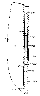
FIG. 1 is a diagram illustrating a first hockey stick configuration.
CA 02485756 2004-11-12
WO 03/097181 (. = PCT/US03/15635ir
7
FIG. 2 is a rear view of a lower portion of the hockey stick illustrated in
FIG. 1
FIG. 3 is a back face view of the hockey stick blade illustrated in FIG. 1
detached
from the hockey stick shaft.
FIG. 4 is a rear end view of the hockey stick blade illustrated in FIG. 3.
FIG. 5 is a diagram illustrating a second hockey stick configuration.
FIG. 6 is a rear view of a lower portion of the hockey stick illustrated in
FIG. 5.
FIG. 7 is a back face view of the hockey stick blade illustrated in FIG. 5
detached
from the hockey stick shaft.
FIG. 8 is a rear end view of the hockey stick blade illustrated in FIG. 7.
FIG. 9 is a bottom end view of the hockey stick shaft illustrated in FIGs. 1
and 5
detached from the blade.
FIG. 10 is a diagram illustrating a third hockey stick configuration.
FIG. 11 is a bottom end view of the hockey stick shaft illustrated in FIGs. 10
and 12 detached from the blade.
FIG. 12 is a rear view of a lower portion of the hockey stick illustrated in
FIG. 10.
FIG. 13 is a back face view of the hockey stick blade illustrated in FIG. 10
detached from the hockey stick shaft.
FIG. 14A is a cross-sectional view taken along line 14---14 of FIGs. 3, 7, and
13
illustrating a first alternative construction of the hockey stick blade.
FIG. 14B is a cross-sectional view taken along line 14---14 of FIGs. 3, 7, and
13
illustrating a second alternative construction of the hockey stick blade.
FIG. 14C is a cross-sectional view taken along line 14---14 of FIGs. 3, 7 and
13
illustrating a third alternative construction of the hockey stick blade.
FIG. 14D is a cross-sectional view taken along line 14---14 of FIGs. 3, 7 and
13
illustrating a fourth alternative construction of the hockey stick blade.
CA 02485756 2004-11-12
WO 03/097181
8
FIG. 14E is a cross-sectional view taken along line 14---14 of FIGs. 3, 7 and
13
illustrating a fifth alternative construction of the hockey stick blade.
FIG. 14F is a cross-sectional view taken along line 14---14 of FIGs. 3, 7 and
13
illustrating a sixth alternative construction of the hockey stick blade.
FIG. 14G is a cross-sectional view taken along line 14---14 of FIGs. 3, 7 and
13
illustrating a seventh alternative construction of the hockey stick blade.
FIG. 14H is a cross-sectional view taken along line 14---14 of FIGs. 3, 7 and
13
illustrating an eighth alternative construction of the hockey stick blade.
FIG. 141 is a cross-sectional view taken along line 14---14 of FIGs. 3, 7 and
13
illustrating a ninth alternative construction of the hockey stick blade.
FIG. 14J is a cross-sectional view taken along line 14---14 of FIGs. 3, 7 and
13
illustrating a tenth alternative construction of the hockey stick blade.
FIG. 14K is a cross-sectional view taken along line 14---14 of FIGs. 3, 7 and
13
illustrating an eleventh alternative construction of the hockey stick blade or
core
component thereof.
FIG. 15A is a flow chart detailing preferred steps for manufacturing the
hockey
stick blade illustrated in FIGs. 14A through 14J.
FIG. 15B is a flow chart detailing preferred steps for manufacturing the
hockey
stick blade or core component thereof illustrated in FIG. 14K.
FIGs. 16A-C together comprise a flow chart of exemplary graphical
representations detailing preferred steps for manufacturing the hockey stick
blade
illustrated in FIG. 14E.
FIG. 17A is a side view of an adapter member employed in a fourth hockey stick
configuration illustrated in FIG. 17D; the adapter is configured to join a
hockey stick
blade, such as the type illustrated in FIGs. 3 and 7, to a hockey stick shaft,
such as is
illustrated in FIGs. 10-12.
FIG. 17B is a perspective view of the adapter member illustrated in FIG. 17A.
FIG. 17C is a cross-sectional view of the adapter member illustrated in FIGs.
17A
and 17B.
K
CA 02485756 2004-11-12 =
WO 03/097181 cat; jt:;i- ;;PCT/US03/15635:j;
9
FIG. 17D is a diagram illustrating a fourth hockey stick configuration
employing
the adapter member illustrated in FIGs. 17A-17C.
FIG. 18A is a cross-sectional view taken along line 14---14 of FIGs. 3, 7, and
13
illustrating an alternative blade construction wherein' the hockey stick blade
comprises a
composite core overlain by a "elastomer" outer surface.
FIG. 18B is a cross-sectional view taken along line 14---14 of FIGs. 3, 7, and
13
illustrating an alternative blade construction wherein the hockey stick blade
comprises a
"elastomer" layer sandwiched between a composite core and composite outer
surfaces.
FIGs. 19A-B are diagrams of the apparatus employed for testing and measuring
performance characteristics of core materials and blade constructs as
described herein.
FIG. 20 is a cross-sectional view of the hockey stick blade generally
illustrated in
FIGs. 10-13 taken along line 20---20 of FIG. 13 ' and depicts an exemplary
construction of
the hockey stick blade, the shaded areas represent areas of the core that are
formed of an
elastomer material while the un-shaded portions of the core represent areas of
the core that
are formed of foam.
Detailed Description Of The Preferred Embodiments
The preferred embodiments will now be described with reference to the
drawings.
To facilitate description, any reference numeral designating an element in one
figure will
designate the same element if used in any other figure. The following
description of the
preferred embodiments is only exemplary. The present invention(s) is not
limited to these
embodiments, but may be realized by other implementations. Furthermore, in
describing
preferred embodiments, specific terminology is resorted to for the sake of
clarity.
However, the invention is not intended to be limited to the specific terms so
selected, and
it is to be understood that each specific term includes all equivalents.
Hockey Stick Configurations
FIGs. 1-13 and 17 are diagrams illustrating first, second, third, and fourth
hockey
stick 10 configurations. Commonly shown in FIGs. 1-13 and 17 is a hockey stick
10
comprised of a shaft 20 and a blade 30. The blade 30 comprises a lower section
70, an
upper section 80, a front face 90, a back face 100, a bottom edge 110, a top
edge 120, a tip
section 130, and a heel section 140. In the preferred embodiment, the heel
section 140
generally resides between the plane defined by the top edge 120 and the plane
defined by
the bottom edge 110 of the blade 30, The shaft 20 comprises an upper section
40, a mid-
CA 02485756 2004-11-12 =
WO 03/097181 ~ fi',..1- '`Rtf fE_ f ^,PCT/US03/15635x(i
section 50, and a lower section 60. The lower section 60 is adapted to be
joined to the
blade 30 or, with respect to the fourth hockey stick configuration illustrated
in FIGs. 17A-
D, the adapter member 1000.
The shaft 20 is preferably generally rectangular in cross-section with two
wide
5 opposed walls 150 and 160 and two narrow opposed walls 170 and 180. Narrow
wall 170
includes a forward-facing surface 190 and narrow wall 180 includes a rearward-
facing
surface 200. The forward-facing surface 190 faces generally toward the tip
section 130 of
the blade 30 and is generally perpendicular to the longitudinal length (i.e.,
the length
between the heel section 140 and the'tip section 130) of the blade 30. The
rearward-facing
10 surface 200 faces generally away from the tip section 130 of the blade 30
and is also
generally perpendicular to the longitudinal length of the blade 30. Wide wall
150 includes
a front-facing surface 210 and wide wall 160 includes a back-facing surface
220.. When
the shaft 20 is attached to the blade 30, the front-facing surface 210 faces
generally in the
same direction as the front face 90 of the blade 30 and the back-facing
surface 220 faces
generally in the same direction as the back face 100 of the blade 30.
In the first and second hockey stick configurations illustrated in FIGs. 1-9,
the
shaft 20 includes a tapered section 330 having a reduced shaft width. The
"shaft width" is
defined for the purposes of this application as the dimension between the
front and back
facing surfaces 210 and 220. The tapered section 330 is preferably dimensioned
so that
when the shaft 20 is joined to the blade 30 the front and back facing'
surfaces 210, 220 of
the shaft 20 are generally flush with the adjacent portions of the front and
back faces 90
and 100 of the blade 30. The lower section 60 of the shaft 20 includes an open-
ended slot
230 (best illustrated in FIG. 9) that extends from the forward-facing surface
190 of narrow
wall 170 preferably, although not necessarily, through the rearward-facing
surface 200 of
narrow wall 180. As best illustrated in FIG. 9, the slot 230 also, but not
necessarily,
extends through the end surface 350 of the shaft 20. The slot 230 is
dimensioned to
receive, preferably slidably, a recessed or tongue portion 260 located at the
heel section
140 of the blade 30.
As best illustrated in FIGs. 3-4 and 7-8, the transition between the tongue
portion
260 and an adjacent portion of the blade 30 extending toward the tip section
130 forms a
frontside shoulder 280 and a back-side shoulder 290, each of which generally
face away
from the tip section 130 of the blade 30. When the tongue portion 260 is
joined to the
shaft 20 via the slot 230 the forward facing surface 190 of the shaft 20 on
either side of the
slot 230 opposes and preferably abuts with shoulders 280 and 290. Thus, the
joint formed
is similar to an open slot mortise and tongue joint. The joint may be made
permanent by
CA 02485756 2004-11-12
WO 03/097181 lF 11 `PCT/US03/15635;
11
use of adhesive such as epoxy, polyester, methacrolates (e.g., PlexusTM) or
any other
suitable material. However, Plexus's has been found.to be suitable for this
application. In
addition, as in the traditional wood construction, the joint may be
additionally
strengthened after the blade 30 and shaft 20 are joined by an overlay of
fiberglass or other
suitable material over the shaft 20 and/or blade 30 or selected portions
thereof.
As illustrated in FIGs. 1-4 and 9 of the first hockey stick configuration, the
tongue
portion 260 comprises an upper edge 300, a -lower edge 310, and a rearward-
facing edge
320. The blade 30 preferably includes an upper shoulder 270 that extends from
the upper
edge 300 of the tongue portion 260 upwardly away from the heel section 140.
When the
tongue portion 260 is joined within the slot 230, the forward-facing surface
190 of the
shaft 200 located directly above the top of the slot 230 opposes and
preferably abuts with
the upper shoulder 270 of the blade 30; the rearward-facing edge 320 of the
tongue 260 is
preferably flush with the rearward-facing surface 200 of the shaft 20 on
either side of the
slot 230; the lower edge 310 of the tongue 260 is preferably flush with the
end surface 350
of the shaft 20; the upper edge 300 of the tongue 260 opposes and preferably
abuts with
the top surface 360 of the slot 230; and the front and back side surfaces 370,
380 of the
tongue 260 oppose and preferably abut with the inner sides 430, 440 of the
wide opposed
walls 150, 160 that define the slot 230.
As illustrated in FIGs. 5-9 of the second hockey stick configuration, the
tongue
portion 260 extends upwardly from the heel section 140 beyond the top edge 120
of the
blade 30 and is comprised of an upper edge 300, a rearward-facing edge 320,
and a
forward-facing edge 340. The blade 30 includes a second set of front and back-
side
shoulders 240 and 250 that border the bottom of the tongue 260 and preferably
face
generally upwardly, away from the bottom edge 110 of the blade 30. When the
tongue
portion 260 is received within the slot 230, the end surface 350 of the shaft
20 on either
side of the slot opposes and preferably abuts with shoulders 240 and 250; the
rearward-
facing edge 320 of the tongue 260 is preferably flush with the rearward-facing
surface 200
of the shaft 20 on either side of the slot 230; the forward-facing edge 340 of
the tongue
260 is preferably flush with the forward-facing surface 190 of the shaft 20 on
either side of
the slot 230; the upper edge 300 of the tongue 260 opposes and preferably
abuts with the
top surface 360 of the slot 230; and the front and back side surfaces 370, 380
of the tongue
260 oppose and preferably abut with the inner sides 430, 440 of the wide
opposed walls
150, 160 that define the slot 230.
Illustrated in FIGs. 10-13 is a third hockey stick 10 configuration. As best
shown
in FIG. 11 the shaft 20 is preferably comprised of a hollow tubular member
preferably
CA 02485756 2004-11-12
WO 03/097181 MPCT/US03/15635-,,
12
having a generally rectangular cross-sectional area throughout the
longitudinal length of
the shaft 20. The blade 30 includes an extended member or hosel portion 450
preferably
comprised of two sets of opposed walls 390, 400 and 410, 420 and a mating
.section 460.
The mating section 460 in a preferred embodiment is comprised of a rectangular
cross
section (also having two sets of opposed walls 390a, 400a, and 410a, 420a)
that is adapted
to mate with the lower section 60 of the shaft 20 in a four-plane lap joint
along the inside,
of walls 150, 160, 170, and 180. The outside diameter of the rectangular cross-
sectional
area of the mating section 460 is preferably dimensioned to make a sliding and
snug fit
inside the hollow center of the lower section 60 of the shaft 20. Preferably,
the blade 30
and shaft 20 are bonded together at the four-plane lap joint using an adhesive
capable of
removably cementing the blade 30 to the shaft 20. Such adhesives are commonly
known
and employed in the industry and include Z-WaxxT" manufactured by Easton
Sports and
hot melt glues. Alternatively, it is also contemplated that the joint between
blade 30 and
shaft 20 be made permanent by use of an appropriate adhesive.
Illustrated in FIG. 17A-D is a fourth hockey stick 10 configuration, which
generally comprises the blade 30 illustrated in FIG. 3, the shaft 20
illustrated in FIGs. 10-
12, and an adapter member 1000 best illustrated in FIGs. 17A-C. The adapter
member
1000 is configured at a first end section 1010 to receive the tongue 260 of
the blade 30
illustrated and previously described in relation to FIGs. 3 and 7. A second
end section
1020 of the adapter member 1000 is configured to be' connectable to a shaft.
In the
preferred embodiment, the second end section 1020 is configured to be
receivable in the
hollow of the shaft 20' illustrated and previously described in relation to
FIGs. 10-12. In
particular, the adapter member 1000 is comprised of first and second wide
opposed walls
1030, 1040 and first and second narrow opposed walls 1050, 1060. The first
wide
opposed wall 1030 includes a front facing surface 1070 and the second wide
opposed wall
includes a back facing surface 1080, such that when the adapter member 1000 is
joined to
the blade 30, the front facing surface 1070 generally faces in the same
direction as the
front face 90 of the blade 30 and the back facing surface 1080 generally faces
in the same
direction as the back face 100 of the blade 30. The first narrow opposed wall
1050
includes forward facing surface 1090 and the second narrow opposed wall 1060
includes a
rearward facing surface 1100, such that when the adapter member 1000 is joined
to the
blade 30, the forward facing surface 1090 generally faces toward the tip
section 130 of the
blade and is generally perpendicular to the longitudinal length of the blade
30 (i.e., the
length of the blade from the tip section 130 to the heel section 140), and the
rearward
facing surface 1100 generally faces away from the tip section 130 of the blade
30.
CA 02485756 2004-11-12
WO 03/097181 ":"ii ir",[ R: CT/US03/15635 'i
13
The adapter member 1000 further includes a tapered section 330' having a
reduced
width between the front and back facing surfaces 1070 and 1080. The tapered
section
330' is' preferably dimensioned so that when the adapter member 1000 is joined
to the
blade 30, the front and back facing surfaces 1070, 1080 are generally flush
with the
adjacent portions of the front and back faces 90 and 100 of the blade 30.
The first end section 1010 includes an open-ended slot 230' that extends from
the
forward facing surface 1090 of narrow wall 1050 preferably, although not
necessarily,
through the rearward facing surface 1100 of narrow wall 1060. The slot 230'
also
preferably, but not necessarily, extends through the end surface 1110 of the
adapter
member 1000. The slot 230' is dimensioned to receive, preferably slidably, the
recessed
tongue portion 260 located at the heel section 140 of the blade 30 illustrated
in FIGs. 3 and
7.
As previously discussed in relation to the shaft illustrated in FIGs. 1-2 and
5-6,
when the slot 230' is joined to the tongue portion 260, the forward facing
surface 1090 on
either side of the slot 230' opposes and preferably abuts the front and back
side shoulders
280, 290 of the blade 30 to form a joint similar to an open slot mortise and
tongue joint.
In addition, the rearward-facing edge 320 of the tongue 260 is preferably
flush with the
rearward facing surface 1100 of the adapter member 1000 on either side of the
slot 230';
the upper edge 300 of the tongue 269, opposes and preferably abuts with the
top surface
20, 360' of the slot 230'; and the front and back side surfaces 370, 380 of
the tongue 260
oppose and preferably abut with the inner sides 430', 440' of the wide opposed
walls 1030
and 1040 of the adapter member 1000.
Moreover, when joined to the blade 30 configuration illustrated in FIG. 3, the
end
surface 1110 of the adapter member 1000 on either side of the slot 230' is
preferably flush
with the lower edge 310 of the tongue 260. Alternatively, when joined to the
blade 30
configuration illustrated in FIG. 7, the end surface 1110 of the adapter
member 1000 on
either side of the slot 230' opposes' and preferably abuts shoulders 240 and
250 and. the
forward facing edge 340 of the tongue 260 is preferably flush with the forward
facing
surface 1090 of the adapter member 1000 on either side of the slot 230'.
The second end section 1020 of the adapter member 1000, as previously stated,
is
preferably configured to be receivable in the hollow of the shaft 20
previously described
and illustrated in relation to FIGs. 10-12, and includes substantially the
same configuration
as the mating section 460 described in relation to FIGs. 10-13. In particular,
the second
end section 1020 in a preferred embodiment is comprised of a rectangular cross
section
WO 03/097181 CA 02485756 2004-11-12
,fõ ; is "ir E,.t,, ..,{ i- j{ = xPCT/US03/15635 ~f
14
having two sets of opposed walls 1030a, 1040a and 1050a, 1060a that are
adapted to mate
with the lower section 60 of the shaft 20 in a four-plane lap joint along the
inside of walls
150, 160, 170, and 180 (best illustrated in FIG. 11). The outside diameter of
the
rectangular cross-sectional area of the second end section 1020 is preferably
dimensioned
to make a sliding fit inside the hollow center of the lower section 60 of the
shaft 20.
Preferably, the adapter member 1000 and shaft 20 are bonded together at the
four-plane
lap joint using an adhesive capable of removably cementing the adapter member
1000 to
the shaft 20 as previously discussed in relation to FIGs. 10-13.
It is to be understood that the adapter member 1000 may be comprised of
various
materials, including the composite type constructions discussed below (i.e.,
substantially
continuous fibers disposed within a resin and wrapped about one or more core
materials
described herein), and may also be constructed of wood or wood laminate, or
wood or
wood laminate overlain with outer protective material such as fiberglass. It
is noted that
when constructed of wood, a player may obtain the desired wood construction
"feel" while
retaining the performance of a composite blade construction since the adapter
member
1000 joining the blade and the shaft would be comprised of wood. Thus, it is
contemplated that performance attributes, such as flexibility, vibration,
weight, strength
and resilience, of the adapter member 1000 may be adjusted via adjustments in
structural
configuration (e.g., varying dimensions) and/or via the selection of
construction materials
including employment of the various core materials described herein.
Hockey Stick Blade Constructions
FIGs. 14A through 14K ' are cross-sectional views taken along line 14---14 of
FIGs. 3, 7, and 13 illustrating construction configurations of the hockey
stick blade 30. It
is to be understood that the configurations illustrated therein are exemplary,
and various
aspects, such as core configurations or other internal structural
configurations, illustrated
or described in relation to the various constructions, may. be combined or
otherwise
modified to facilitate particular design 'purposes or performance criteria. '
FIGs. 14A
through 14J and 18A-B illustrate constructions that employ one or more inner
core
elements 500 overlain with one or more layers 510 comprising one or more plies
520 of
substantially reinforcing fibers or filaments disposed in a hardened matrix
resin. The
reinforcing fibers or filaments may be substantially continuous.
FIG 14K illustrates yet another alternative blade construction or core
component
construction comprising non-continuous fibers disposed in a matrix or resin
base (often
referred to as bulk molding compound ("BMC"). FIGs. 15A and 16A-16C are flow
charts
CA 02485756 2004-11-12
WO 03/097181 t=_; v~ ~ .= 4 F "u,jPCT/US03/15635j
detailing preferred steps of manufacturing the blade constructions illustrated
in FIGs. 14A-
14J and 18A-B. FIG 15B is a flow chart detailing preferred steps of
manufacturing the
blade or core component construction illustrated in FIG. 14K.
It is to be understood that the dimensions of the hockey sticks and the blades
5 thereof disclosed herein may vary depending on specific design criteria.
Notwithstanding,
it contemplated that the preferred embodiments are capable of being
manufactured so as to
comply with the design criteria set forth in the official National Hockey
League Rules
(e.g., Rule 19) and/or the 2002 National Collegiate Athletic Association
("NCAA") Men's
and Women's Ice Hockey Rules (e.g. Rule 3). Hence, it is contemplated that the
hockey
10 stick and blade constructions and configurations disclosed herein are
applicable to both
forward and goaltender sticks.
Commonly shown in FIGs. 14A-14J and 18A-18B are one or more inner core
elements identified as 500a-500c (identified as elements 1500 in FIG. 18A-B,
and 1510 in
FIG. 18B), one or more layers 510 (identified as elements 1500 in FIG. 18A-B,
and 1520
15 in FIG. 18B) comprising one or more plies identified as 520a-520d of
substantially
continuous fibers disposed in a hardened matrix or resin based material. Also
commonly
shown in Figures 14A-14F and 141-14J are one or more internal bridge
structures
commonly identified by call out reference numeral 530, which extend generally
in a
direction that is transverse to the front and back faces 90, 100 of the blade
30. Prior to
setting forth a detailed discussion of each of these alternative
constructions, a discussion
of the construction materials employed is set forth.
Construction Materials
The hockey stick blades 30 illustrated in the exemplary constructions of
FIGs. 14A-14K and 18A-B generally comprises one or more core elements (e.g.,
element
500) and one or more exterior plies (e.g., element 520) reinforcing fibers or
filaments
disposed in a hardened matrix resin material. Presently contemplated
construction
materials for each of these elements are described below.
Core Materials
Depending on the desired performance or feel that is sought, the inner core
elements 500 may comprise various materials or combinations of various
materials. For
example, a foam core element may be employed in combination with an
"elastomer" (i.e.,
elastomer) core and/or a core made of discontinuous or continuos fibers
disposed in a resin
matrix.
0 CA 02485756 2004-11-12
WO 03/097181 (( PCT/US03/15635:,,..
h"'{l~,F, me~E` r ` ~I vl` ~I.~l~ Slsn~~ .vnlG a .,i[ n ~nrvlf [Iw.LF ..uelE
.,' .IF
16
Foam: Foam cores such as those comprising formulations of expanding syntactic
or non-syntactic foam such as polyurethane, PVC, or epoxy have been found to
make
suitable inner core elements for composite blade construction. Such foams
typically have
a relatively low density and may expand during heating to provide pressure to
facilitate the
molding process. Furthermore, when cured such foams are amenable to attaching
strongly
to the outer adjacent plies to create a rigid structural sandwich
construction, which are
widely employed in the industry. Applicants have found that polyurethane foam,
manufactured by Burton Corporation of San Diego, California is suitable for
such
applications.
Perhaps due to their limited elasticity, however, such foam materials have
been
found amenable to denting or being crushed upon singular or repetitive impact,
such as
that which occurs when a puck is shot. Because the inner cores of conventional
hockey
stick structures are essentially totally comprised of foam, compromise in the
durability
and/or the consistent performance of the blade structure with time and use may
occur.
Elastomer or Rubber: The employment of elastomers, or rubbery materials, as
significant core elements in hockey sticks, as described herein, is novel in
the composite
hockey stick industry. The term "elastomer" or "elastomeric", as used herein,
is defined
as, or refers to, a material having properties similar to those of vulcanized
natural rubber,
namely, the ability to be stretched to approximately twice its original length
and to retract
rapidly to approximately its original length when released and includes the
following
materials:
(1) vulcanized natural rubber;
(2) synthetic thermosetting high polymers such as styrene-butadiene
copolymer, polychloroprene (neoprene), nitrile rubber, butyl rubber,
polysulfide rubber
("Thiokol"), cis-1, 4-polyisoprene, ethylene-propylene terpolymers (EPDM
rubber),
silicone rubber, and polyurethane rubber, which can be cross-linked with
sulfur, peroxides,
or similar agents to control elasticity characteristics; and
(3) Thermoplastic elastomers including polyolefms or TPO rubbers, polyester
elastomers such as those marketed under the trade name "Hytrel" by E.I. Du
Pont; ionomer
resins such as those marketed under the tradename "Surlyn" by E.I. Du Pont,
and cyclic
monomer elastomers such as di-cyclo pentadiene (DCPD).
Notably, composite structures employing elastomer cores, as a general
principle,
do not follow the classic formulas for calculating sandwich loads and
deflections. This is
CA 02485756 2004-11-12 =
WO 03/097181 JCT/US03/15635,:,..
tit nõ .,~ ,,.. -u'st; 4:1V 17
so because these materials are elastic and therefore are less amenable to
forming a rigid
internal structure with the exterior skin or plies of the sandwich.
Consequently, it is. no
surprise that composite hockey stick structures (e.g., composite blades)
comprising
elastomer cores are absent from the industry. Notwithstanding, applicants have
found that
the employment of such elastomer cores individually or in combination with
other core
materials, such as foam, are capable of providing desirable feel and/or
performance
characteristics.
For example, the sound that is generated when a hockey puck is struck by a
hockey
stick can be modified with the employment of such elastomer cores to produce a
uniquely
10' - pleasing sound to the player as opposed to the "hollow-pingy" type sound
that is typically
created with traditional composite hockey sticks. Further, the resilient
elasticity of
elastomers make them suited to the unique dynamics endured by hockey stick
blades and
components. Unlike conventional foam core materials,, elastomer cores can be
chosen
such that their coefficients of restitution (CORs) are comparable to wood, yet
by virtue of
their resilient properties are capable of withstanding repetitive impact and
thereby provide
consistent performance and suitable durability.
Moreover, employment of elastomer core materials have been found to impact or
dampen the significance of the vibration typically produced from a traditional
foam core
composite blade and thereby provide a manner of controlling or tuning the
vibration to a
20, desired or more desirable feel.
In addition, because elastomers are available with significant ranges in such
mechanical properties as elasticity, resilience, elongation percentage,
density, hardness,
etc. they are amenable to being employed to achieve particular product
performance
criteria. For example, an elastomer may have properties that are suitable for
providing
both a desired coefficient of restitution while at the same time suitable for
achieving the
desired vibration dampening or sound. Alternatively, a combination of
elastomers may be
employed to achieve the desired performance attributes, perhaps one more
suited for
dampening while the other being better suited for attaining the desired
coefficient of
restitution. Thus, it has been found that the use of elastomer cores can
facilitate unique
control or modification over performance criteria.
Moreover, it is to be understood that the elastomer may be employed in a
limited
capacity and need not constitute the totality, or even a majority, of the
core. This is
especially significant in that elastomer materials typically have densities
significantly
greater than conventional foam core materials, and hence may significantly add
to the
CA 02485756 2004-11-12
WO 03/097181 EE t~ PCT/US03/15635
11-.5f Ira
18
overall weight of the blade and the hockey stick.. Thus, for example, it may
be preferable
that elastomer materials be placed in discrete strategic locations -- such as
in and/or
around a defined impact zone of the blade, along the outer circumference of
the blade, or
along vibration transmission pathways perhaps in the hosel, heel or along the
edge of the
5' blade. They may be placed in vertical and/or horizontal lengths within the
core at spaced
intervals. For example, reference is made to FIG. 20, shown therein is a cross-
sectional
diagram of the hockey stick blade taken generally longitudinally along the
plane of the
hockey stick blade 30 as identified by line 20---20 in FIG. 13. The elastomer
core
components are identified by shading and the foam core components are
identified as the
portions of the core that are not shaded. Moreover, it is to be understood
that 'dimensions
(e.g., thickness, height, width) of one or more of the core materials, whether
an elastomer
or otherwise, may be varied relative to the external blade 30 dimensions, or
relative to
other internal blade components or structures. Thus, for example it is
contemplated that
the thickness of the core may "be thinner at the tip section 130 an along the
upper edge 120
than at regions more proximate to the heel region 140 and the bottom or lower
edge 110.
Thus for example in FIG. 20 it is contemplated that the thickness of the more
distally
positioned elastomer core element is generally thinner than the more
proximately
positioned elastomer core element. The foam core element interposed between
the distally
and proximately positioned elastomer core element would have a thickness
dimension
generally in between the those of the adjacent elastomer core elements.
Furthermore, it is to be understood that elastomer materials may be combined
in
discrete layers and/or sections with more traditional core structures (e.g.,
foam, wood, or
wood laminate) and/or other materials such as plastics, or other fiber
composite structures,
such as a material comprised of continuous or discontinuous fibers or
filaments disposed
in a matrix resin. In addition, it is also contemplated that combinations of
core materials
may be blended or otherwise mixed.
Preferred Characterizations and Implementations of Elastomeric Materials
Preferred characterizations of elastomer materials and preferred
implementations
of elastomer cores and structures are set forth in the following paragraphs.
It is to be
understood that each of the following characterizations and/or implementations
may be
employed independently from or in combination with one or more of the other
preferred
characterizations and/or implementations to further define the preferred
hockey stick and
blade configurations, embodiments, and constructions.
CA 02485756 2004-11-12
WO 03/097181 ,PCT/US03/15635.,:..
19
First Preferred Characterization: A first preferred characterization of the
materials
that fall within the definition of "elastomer" as used and described herein
include materials
that have a ratio of the specific gravity ("SG") to the coefficient of
restitution ("COR") less
than or equal to five (5.0), as described by the formula set forth below:
(1) SG = COR < 5.0
Where: SG: is the ratio of the weight or mass of a given
volume of any substance to that of an equal volume of water at four degrees
Celsius; and
COR: also known as the "restitution coefficient",
can vary from 0 to 1 and is generally the relative velocity of two bodies of
mass after impact to that before impact as further described by the
"Coefficient of Restitution Test", procedure and apparatus set forth below
and illustrated in FIGs. 19A-B.
"Coefficient of Restitution Test": The foregoing "Coefficient of Restitution
Test"
procedure is novel in the hockey stick industry. The test procedure is similar
in some
aspects to ASTM Designation F 1887-98 entitled Standard Test Method for
Measuring the
Coefficient of Restitution (COR) of Baseballs and Softballs, which was
published in
February 1999. FIGs. 19A-B are illustrations of the testing apparatus. The
procedure is
intended to set forth the method of measuring the coefficient of restitution
of core
materials used in composite constructs, particularly hockey stick blades and
component
parts, as described herein. Further, the procedure is intended to establish a
single,
repeatable, and uniform test method for testing such core materials.
The test method is based on the velocity measurement of a steel ball bearing
before
and after impact of the test specimen. As defined herein, the "coefficient of
restitution"
(COR) is a numerical value determined by the exit speed of the steel ball
bearing after
contact divided by the incoming speed of the steel ball bearing before contact
with the test
specimen. The dimensions of the test specimen are 7 +/- 0.125 x 2 +/-0.125 x
0.25+/-
0.0625 inches. Notwithstanding the 'foregoing dimensional tolerances of the
test
specimens, it is to be understood that the specimens are to be prepared with
dimensions
that are as accurate as reasonably possible when employing this test
procedure.
Once the test specimen is prepared, it is firmly secured to a massive, rigid,
flat
wall, which is comprised of a 0.75 inch-thick steel plate mounted on top of a
2.50 inch-
thick steel table. The sample specimen is secured to the steel plate via
clamps positioned
CA 02485756 2004-11-12
WO 03/097181 PCT/US03/15635
at the ends of the specimen, approximately equal distance from the specimens
geometric
center. The clamps should be sufficiently tightened to the steel plate over
the specimen to
be tested so as to inhibit the specimen from moving when impacted by the steel
ball
bearing. Clamp placement should be approximately 5.0 inches apart or 2.5
inches from
5 the specimens center, which resides in the intended impact zone.
The steel ball bearing is made of 440 C grade steel and has a Rockwell
hardness
between C58-C65, a weight of 66.0 grams +/- 0.25 grams, a sphericity of 0.0001
inches,
and a diameter of 0.75 inches +/- 0.0005 inches. See ASTM D 756 entitled
Practice for
Determination of Weight and Shape changes of Plastic Under Accelerated Service
10 Conditions. Such spherical steel ball bearings meeting the foregoing
criteria may be
procured from McMaster Carr, USA or any other suitable or available source or
vendor.
Electronic speed monitors measure the steel ball bearings speed before and
after
impact with the test specimen. Each speed monitor is comprised of generally
two
components: (1) a vertical light screen and (2) a photoelectric sensor. The
vertical light
15 screens are mounted 2.0 +/- 0.125 inches apart, with the lower light screen
being mounted
5 +/- 0.125 inches above the top surface of the 0.75 inch thick steel plate.
Two
photoelectric sensors, one located at each screen, trigger a timing device on
the steel ball
bearing passage thereby measuring the time for the ball to traverse the
distance between
the two vertical planes before and after impact with the test specimen. The
resolution of
20 the measuring apparatus shall be +/- 0.03 m/s.
The test room shall be environmentally controlled having a temperature of 72
OF
+/- 6 OF, a relative humidity of 50% +/- 5%. Prior to testing, the specimens
are to be
conditioned by placing them for at least 12 hours in an environmentally
controlled space
having the same temperature and relative humidity as the test room.
The steel ball bearing shall be dropped from a height of 30.5 inches +/- 0.2
inches.
The ball shall be dropped 25 times on the specimen via the employment of a
suitable
release device, such as a solenoid. A minimum of a 45-second rest period is
required
between each drop. The average of the 25 COR values for each specimen is used
to
determine the COR of the specimen, in accordance with the following formulae:
(2) COR = Vb/a = 1/25 [(Vbl/al) + (Vb2/a2) + (Vb3/a3).... +
V b23/a23) + (= b24/Va24) + ` V b25/a25)]
CA 02485756 2004-11-12
WO 03/097181 n., Ã PCT/US03/15635y;
~j ,i! 3,! .U .. -,-
21
Where: Va = incoming speed adjusted or compensated for the effects
of gravity, and
Vb = exit speed adjusted or compensated for the effects of
gravity.
Data acquisition hardware such as that marketed under the trade name "Lab
View"
and data acquisition circuit boards may be obtained from National Instruments
Corporation located in Austin, Texas; and suitable wiring from sensors to
acquisition ports
may be obtained from Keyence Corporation of America located in Torrance,
California.
Second Preferred Characterization: A second preferred characterization of the
materials that fall within the definition of "elastomeric" as used and
described herein
include materials that have an ultimate elongation equal to or greater than
100% in
accordance with the following formula:
(3) Ultimate Elongation Percentage = { [(final length at rupture) -
(original length)] _ [original length] } x 100
Where: Ultimate Elongation: also referred to as the breaking
elongation, is the elongation at which specimen rupture occurs in the
application of continued tensile stress as measured in accordance with
ASTM Designation D 412 Standard Test Methods for Vulcanized Rubber
and Thermoplastic Elastomers - Tension (August 1998).
20. Third Preferred Characterization: A third preferred characterization of
the
materials that fall within the definition of "elastomer" as used and described
herein include
materials that are capable of undergoing a subsequent heating and pressure
commensurate
with curing and molding (e.g., such as the RTM process previously discussed or
the
process described in relation to Figs. 15A and 16), yet still fall within the
definition of an
elastomer as defined herein. For example in a typical molding process such as
that
disclosed in relation to the process described in Fig. 15A, the blade assembly
may be
subject to a cure temperature between 200 and 350 degrees Fahrenheit for a
period ranging
from 10 to 20 minutes and commensurate pressure resulting therefrom. Hence,
the third
preferred characterization relates to employment of a material that can
undergo such
processing and still fall within the definition of an elastomer as described
herein.
First Preferred Implementation: A first preferred implementation of an
elastomer
core material in a composite structure, such as a hockey stick blade, as used
and described
= CA 02485756 2004-11-12
WO 03/097181 ((''r ((;`; "'(". `` is. I :';Ãi Ems ; PCT/US03/15635 1E
22
herein is defined by the ratio of the cross-sectional area comprising an
elastomer core
divided by the total cross sectional area, in accordance with the following
formula:
(4) AE _ AT > 0.25
Where: AE: is the cumulative area at any given cross-section of
the blade that is occupied by an elastomer; and
AT: is the total area at the same cross-section of the
blade.
The foregoing preferred implementation is applicable to any cross-section of
the
blade 30 regardless of where along the blade that cross-section is taken. It
is to be
understood, however, that this preferred implementation employs a cross-
sectional area
that is generally perpendicular to the front and back faces 90, 100 of the
blade 30 such as
those illustrated in FIGs. 14A-14K and 18A-B.
Second Preferred Implementation: A second preferred implementation of an
elastomer core in a composite structure, such as a hockey stick blade, as used
and
described herein is defined by the ratio of the thickness of the elastomer
divided by the
total thickness of the blade, in accordance with the following formula:
(5) TE = TT > 0.25
Where: TE: is the cumulative thickness of all elastomer core
materials at any given cross-sectional plane of the blade, as described
above in relation to the first preferred implementation, and as measured
along a line on that cross-sectional plane that is generally normal to one or.
both (i.e., at least one) of the faces 90, 100 of the blade 30 at the point
where the line intersects the face; and
TT: is the total thickness of the blade as measured along
the same line of measurement employed in the measurement of TE.
Alternative First and Second Preferred Implementations: Alternative first and
second preferred implementations of an elastomer core material in a composite
structure,
such as a hockey stick blade, as used and described herein is defined as set
forth in the first
and second preferred implementations described above in relation to equations
(4) and (5),
except that:
CA 02485756 2004-11-12
WO 03/097181 i~ ;,; r~ :: "r (~ra~ r= (~ PCT/US03/15635 ii
23
AT: is defined as AT', and is no longer the total area at the cross-section of
the
blade but rather is the total area at the cross-section occupied by fibers or
filaments
disposed in a hardened matrix or resin material; and
TT: is defined as TT', and is no longer the total thickness of the blade as
measured along the same line of measurement employed in the measurement of TE,
but
rather is the total thickness of the layer(s) comprising fibers or filaments
disposed in a
hardened matrix or resin material as measured along the same line of
measurement
employed in the measurement of TE.
Elastomer Core Testing and Related Data
Four elastomer core materials made of silicone rubber, which are identified in
the
following tables as M-1 to M-4, were prepared and the samples were subjected
to COR
comparison testing. The cores were compared to materials traditionally
employed in
conventional hockey stick blades, in particular wood, resin matrix, foam, and
plastic.
Table 1 is a compilation of that data.
Table 1
Hardness Tensile Elongation Tear
Material/ Strength Strength
Description S.G. Die B COR SG COR
[Shore A
points] [psi] [%] [lbs/inch]
M-1 1.28 56 900 120 40 0.541 2.37
M-2: 1.15 5 436 731 110 0.590 1.95
M-3 1.13 20 914 600 132 0.614 1.84
M-4 1.11 40 525 225 100 0.635 1.75
Wood (Ash) 0.69 0.564 1.22
Resin Matrix 8.20 0.832 9.86
Foam 0.14 --'
Plastic 1.01 0.667 1.51
1 The steel ball bearing did not bounce-off the foam sample when it was
tested for COR and therefore the COR measurement is negligible.
1
CA 02485756 2004-11-12
WO 03/097181 !{ it S 03 ; PCT/US03/15635 mit
24
The values of specific gravity, hardness, tensile strength, elongation
percentage
and tear strength for the silicone rubber samples M-1 to M-4, were provided by
the
manufacturer and are understood to comply with ASTM measurement standards.
Table 2
is a compilation of the trade names and manufacturers of the materials set
forth above in
Table 1.
Table 2,
Material/ Manufacturer Trade Name
Description
M-1 Dow Corning Silastic J
M-2: Dow Corning HS IV RTV High Strength
M-3 Dow Corning Silastic S-2 RTV
M-4 Circle K GI-1040 RTV
Resin Matrix: Dow Chemical D.E.R. 332 Epoxy Resin
Foam Burton Corporation, San Diego, CA BUC-500 Foam
Plastic Generic Acrylonitrile Butadine Styrene Resin ("ABS")
As noted in Table 1, the specific gravity for each of the silicone rubber core
materials M-1 to M-4 was significantly greater than the foam yet significantly
less than the
resin. In addition, the measured COR for each of the silicone rubber core
materials were
comparable to the COR measured for the wood specimen. Furthermore, the
measured
COR of the silicone rubber samples exhibited a generally linear increase with
decreasing
S.G. values.
Thin and thick walled composite hockey stick blade constructs were
manufactured
with cores made of each of the four silicone rubber samples as well as the
foam sample.
The thin and thick walled composite blades were manufactured using the same
blade mold
and generally in accordance with the procedure described in relation to FIG.
15A. It is to
be understood the phrase thin and thick walled refers to the walls of the
blade between
which the core material is interposed. Hence a thick walled blade would be
formed with a
thicker layer of fibers disposed within a hardened resin matrix material than
a thin walled
blade.
The constructs were then subjected to comparative COR testing. The same test
apparatus was employed as discussed in relation to the COR Test Procedure set
forth
above, except that the steel ball bearing used in the test had a weight of
222.3 +/- 0.25
grams, a sphericity of 0.0001 inches, and a diameter of 1.00 +/- 0.0005
inches. In
= CA 02485756 2004-11-12
WO 03/097181 [ ~;a6 Ir: ' r ' IL[[ ; 11:1 PCT/US03/565
addition, since the specimens were comprised of composite blade constructs,
the specimen
dimensions set forth in the COR Test Procedure set forth above also were
different.
Table 3 sets forth the COR data of these tests.
Table 3
Material/ COR of Thin Blade Construct (tested) COR of Thick Blade Construct
(tested)
Description
M-1 0.892 0.899
M-2 0.925 0.938
M-3 0.929 0.875
M-4 0.945 0.961
Foam 0.944 0.988
5 Notably, in all but one' of the test specimens (M-3) an increase in the COR
was
measured with an increase in wall thickness of the blade. Further, the
greatest percent
increase in the COR from the thick walled blade over the thin walled blade was
measured
in the foam core blade construct.
Comparative spring rate testing was conducted on the silicone rubber samples
(M-
10 1 to M-4) and the foam core for both a thin and thick walled blade
constructs. The test
consisted of placing a load on the blade construct at a uniform load rate of
0.005
inches/second and obtaining load versus deflection curves. The maximum loads
for the
thin and thick walled composite blade constructs was 80 lbs and 150 lbs,
respectively.
The loads were placed on the same position on each of the blade constructs.
The
15 following data set forth in Table 4 below was obtained:
= CA 02485756 2004-11-12 =
WO 03/097181 jf,.lj -:PCT/US03/15635;`
26
Table 4
Material/ Spring Rate of Thin Blade Construct Spring Rate of Thick Blade
Construct
Description (tested [lbs/in]) (tested [lbs/in])
M-1 6228.8 6877.0
M-2: 3674.5 5601.0
M-3 4580.0 6768.5
M-4 4850.9 6077.7
Foam 6131.9 6139.3
As can be seen from the data, the spring rate showed a significant increase
between
the thin and thick blade constructs for the silicone samples. The spring rate
in the foam
core construct, on the other hand, did not markedly increase with increased
wall thickness.
Comparative vibration testing was also conducted on the thin and thick blade
composite constructs. Measurements of maximum vibration amplitudes (measured
in
gravity increments) and a qualitative comparison of decay times were recorded.
The test
consisted of securing the composite blade construct at the hosel against an L-
bracket and
deflecting the blade at its toe a distance of 0.5 inches. Upon release of the
deflected blade,
vibration of the blade was measured via an accelerometer placed at 1.25 inches
from the
toe of the blade. The following data set forth below in Table 5 was recorded:
Table 5
Max Accel. of Thin Decay Time of Thin Max Accel. of Decay Time of
Material/ Thick Blade Thick Blade
Blade Construct Blade Construct
Description (tested [g's]) (tested [s]) Construct (tested Construct (tested
[g's]) [s])
M-1 57.7 0.67 88.0 0.54
M-2 81.6 0.68 83.9 0.82
M-3 77.2 0.87 93.7 0.72
M-4 82.2 0.78 94.6 0.70
Foam 139.0 1.09 95.3 0.73
A similar vibration test was conducted on an all wood hockey stick blade, the
data
is set forth in Table 6 below:
CA 02485756 2004-11-12
WO 03/097181
PCT/US03/15635 mtt
27
Table 6
Material/ Max Accel. Decay Time
Description (tested [g's]) (tested [s])
Wood 18.7 1.09
Notably, the measurement of maximum acceleration is a measure of the initial
vibration of the blade that occurs subsequent release of the deflected blade
and is a
reflection of the blade's capability to transmit vibration. The measurement of
decay time
is a measure of the duration or time required for the vibration of the blade
to dissipate or
be absorbed and therefore is a measure of the blades capability of dampening
vibration.
With respect to the maximum acceleration data measured from the testing of the
thin walled blade constructs, it is noted that the silicone rubber core
constructs measured
significantly less than the foam core construct. In addition, with respect to
the decay times
of the thin walled blade constructs, it is noted that the silicone rubber core
constructs
measured significantly less than the decay time of the foam core construct.
When one compares the maximum acceleration between the thin walled blade
constructs and the thick walled blade constructs, it is noted that the
silicone rubber core
constructs tended to increase with blade wall thickness while the maximum
acceleration of
the foam core construct reflected a significant decrease. When one compares
the decay
times between the thin walled blade constructs and the thick walled blade
constructs, it is
noted that the silicone rubber constructs generally measured a slight decrease
with
increasing blade wall thickness where as the foam construct measured a
significantly
larger decrease in decay time with increasing blade wall thickness.
In addition, a qualitative comparison to the all wood blade construct
indicates that
although the maximum acceleration or vibration of the all wood construct
measured less
than any of the silicone rubber core constructs, the decay time was
significantly greater in
the all wood constructs than the silicone-rubber constructs.
Thus, the data suggest that an elastomer core is capable of effecting in a
unique
manner not only the spring rate and the COR as previously described and
discussed, but it
is also capable of providing a reduced decay time when compared to the foam
and wood
blade constructs as well as a decreased maximum acceleration closer to a wood
blade
construct than a traditional foam core construct.
"Bulk Molding Compound" Cores: Bulk molding compounds are generally
defined as non-continuous fibers disposed in a matrix or resin base material,
which when
= CA 02485756 2004-11-12
WO 03/097181 PCT/US03/15635
T-11
`
28
cured become rigid solids. Bulk molding compound can be employed as an inner
core
element or can form the totality of the blade 30 structure. This type of blade
30 or core
500 construction is best illustrated in FIG. 14K. When employed as either a
blade 30 or
core component 500 thereof, it is preferable that the bulk molding compound be
cured in
an initial molding operation, preferred steps for which are described in FIG.
15B.
Initially, bulk molding compound is loaded'into a mold configured for molding
the desired
exterior shape of the blade 30 or core element 500 (step 700 of FIG. 15B).
With respect to
the loading of the mold, it has been found preferable to somewhat overload the
mold with
the compound so that when the mold is sealed or 'closed, the excess compound
material
exudes from the mold. Such a loading procedure has been found to improve the
exterior
surface of the cured molded structure. Once the mold is loaded, heat is
applied to the
mold for curing (step 710), and the cured blade 30 or core element 500 is
removed from
the mold (step 720). Additionally, if required, the mold is finished to the
desired
appearance as a blade 30, or prepared for incorporation in the blade 30 as a
core element
500.
Ply Materials/ Fibers & Matrix/Resin
As used herein, the term "ply" shall mean "a group of fibers which all run in
a
single direction, largely parallel to one another, and which may or may not be
interwoven
with or stitched to one or more other groups of fibers each of which may or
may not be
disposed in a different direction." Unless otherwise defined, a "layer" shall
mean one or
more plies that are laid down together.
The fibers employed in plies 520 may be comprised of carbon fiber, aramid
(such
as KevlarTM manufactured by Dupont Corporation), glass, polyethylene (such as
SpectraTM
manufactured by Allied Signal Corporation), ceramic (such as Nextel'
manufactured by
3m Corporation), boron, quartz, polyester or any other fiber that may provide
the desired
strength. Preferably, at least part of one of the fibers is selected from the
group consisting
of carbon fiber, aramid, glass, polyethylene, ceramic, boron, quartz, and
polyester; even
more preferably from the group consisting of carbon fiber, aramid, glass,
polyethylene,
ceramic, boron, and quartz; yet even more preferably from the group consisting
of carbon
fiber, aramid, glass, polyethylene, ceramic, and boron; yet even more
preferably from the
group consisting of carbon fiber, aramid, glass, polyethylene, and ceramic;
yet even more
preferably from the group consisting of carbon fiber, aramid, glass, and
polyethylene; yet
even more preferably from the group consisting of carbon fiber, aramid, and
glass; yet
even more preferably from the group consisting of carbon fiber and aramid; and
most
preferably comprises carbon fiber.
CA 02485756 2004-11-12 0 WO 03/097181 9((f f{ . {`ry PCT/US03/15635
29
It has been found preferable that each uni-directional fiber ply be oriented
so that
the fibers run in a different and preferably a perpendicular direction from
the underlying or
overlying uni-directional ply. In a preferred construction lay-up, each ply is
oriented so
that the fibers run at preferably between + I - 30 to 80 degrees relative to
the longitudinal
length of the blade 30 (i.e., the length from the heel section 140 to the tip
section 130), and
more preferably between +/- 40 to 60 degrees, yet more preferably between +I-
40 to 50
degrees, even more preferably between 42.5 and 47.5 degrees, and most
preferably at
substantially +l- 45 degrees. Other ply orientations may also be independently
or in
conjunction with the foregoing orientations. For example, it has been found
preferable
that an intermediate zero degree oriented ply be included between one or more
of the plies
520 to provide additional longitudinal stiffness to the blade 30. In addition,
for example, a
.woven outer ply (made of e.g., KevlarTM, glass, or graphite) might be
included to provide
additional strength or to provide desired aesthetics. furthermore, one or more
plies may be
employed which may or may not be uni-directional or woven. Moreover, it is to
be
understood that additional plies may be placed at discrete locations on the
blade 30 to
provide additional strength or rigidity thereto. For example, additional plies
may be
placed at or around the general area where the puck typically contacts the
blade 30 during
high impact shots (such as a slap shot), in an area where the blade typically
meets the ice
surface such as at or about the bottom edge 110, or in the general area on the
blade 30 that
is adapted to connect to the hockey stick shaft 20 or an adapter 1000 such as
that
illustrated in FIGs. 17A-D, for example the heel region 140, tongue 260 or
hosel 450
portion of the blade 30,
The matrix or resin-based material is selected from a group including:
(1) thermoplastics such as polyether-ketone, polyphenylene sulfide,
polyethylene,
polypropylene, urethanes (thermoplastic), and Nylon-6, and (2) thermosets such
as
urethanes (thermosetting), epoxy, vinylester, polycyanate, and polyester.
In order to avoid manufacturing expenses related to transferring the resin
into the
mold, the matrix material may be pre-impregnated into the fibers or filaments,
plies 520 or
layers 510 prior to the uncured blade assembly being inserted into the mold
and the mold
being sealed. In addition, in order'to avoid costs associated with employment
of woven
sleeve materials, it may be preferable that the layers 510 be comprised of one
or more
plies 520 of non-woven uni-directional fibers. Applicants have found that a
suitable
material includes uni-directional' carbon fiber tape pre-impregnated with
epoxy,
manufactured by Hexcel Corporation of Salt Lake City, Utah, and also S & P
Systems of
San Diego, California. Another suitable material includes uni-directional
glass fiber tape
pre-impregnated with epoxy, also manufactured by Hexcel Corporation. Yet
another
L 4 1
CA 02485756 2004-11-12
WO 03/097181 =~; E(õi' n=1 =.. L j it a~~ [ o (I -PCT/US03/15635
suitable material includes uni-directional KevlarTM fiber tape pre-impregnated
with epoxy,
also manufactured by Hexcel Corporation.
Employment of such pre-impregnated materials has been found by applicants to
be
particularly suitable for serving as an adhesive to secure the layers of
fibers or one or more
5 plies to one another, as well as to the core or other structural component.
Hence, the
employment of these materials may serve to facilitate the fixing of the
relative position of
the pre-cured blade assembly components. Moreover, such pre-impregnated
materials
have been found advantageous when employed internally in so much as the resin
need not
flow or otherwise be transferred into the internal portions of the blade 30
during the curing
10 molding and curing process of the blade assembly. For example, internal
structures, such
as the bridge structures 530 of the various blade 30 constructions illustrated
in FIGs. 14B-
14F, 141 and 14J, as well as the internal ply layers 510 best illustrated in
FIGs. 14G and
14J and 18B, are particularly suited to being formed from such pre-impregnated
materials.
By pre-positioning the resin in the desired locations, control over the
disposition of the
15 resin in the internal structure component(s) can be exercised, such as at
the bridge
structure 530 as well as the internal layers 510 or plies 520.
Exemplary Alternative Blade Construction Configurations
Exemplary alternative blade 30 constructions illustrated in Figures 14A
through
14K and 18A-B are described in turn below. It is to be understood that the
various cores
20 may be comprised of various materials (e.g., foam, wood, wood laminate,
elastomer
material, bulk molding compound, etc.) to achieve desired performance
characteristics
and/or unique feel.
With reference to FIG. 15A, the blade 30 constructions illustrated in FIGs.
14A
through 14F and 18B are generally constructed in accordance with the following
preferred
25 steps. First, one or more plies 520, layers, or groups of fibers or
filaments are wrapped
over one or more inner core elements 500a-500c (e.g., wood, wood laminate,
elastomer
material, foam, bulk molding compound, etc.), which individually or in
combination
generally form the shape of the blade 30 illustrated in FIGs. 3, 7, or 13
(step 600) to create
an uncured blade assembly.
30 Once the uncured blade assembly is prepared, it is inserted into a mold
that is
configured to impart the desired exterior shape of the blade 30 or component
thereof (step
610 of FIG. 15A). The mold is then sealed, after which heat is applied to the
mold to cure
the blade assembly (step 620 of FIG. 15A). The blade 30 is then removed from
the mold
and finished to the desired appearance (step 630 of FIG. 15A). The finishing
process may
CA 02485756 2004-11-12
WO 03/097181 "/ (I,n PCT/US03/15635 rt
31
include aesthetic aspects such as paint or polishing and also may include
structural
modifications such as deburring. Once the blade 30 is finished, the blade 30
is then ready
for attachment to the shaft 20.
It is to be understood that in order to avoid subsequently injecting resin or
matrix
material into the mold after the blade assembly is placed therein (such as in
a conventional
resin transfer molding (RTM) processes described above) a preferred
construction process
employs fibers, plies or layers of fiber plies that are pre-impregnated with a
resin or
matrix, as previously noted. An RTM method or a combination of an RTM and pre-
preg
method process may be employed, however, if desired for a given application.
As shown in the preferred embodiment illustrated in FIG. 14A, a three-piece
core
500a, 500b, and 500c is employed. Overlaying the centrally positioned core
element 500b
are two plies 520a and 520b. In application, plies 520a and 520b may be
wrapped around
core element 500b as a single layer. Once plies 520a and 520b are wrapped
around the
core element 500b, plies 520c, 520d, and 520e are wrapped over plies 520a and
520b and
around core elements 500a and 500c. The uncured blade assembly is then
inserted into a
suitable mold configured to impart the desired exterior shape of the blade 30,
as previously
discussed in relation to step 610 of FIG. 15A. Once cured, plies 520a and 520b
create
internal bridge structures 530 that extend from one side of the blade 30 to
the other (i.e.,
from the inner facing surface of ply 520c on one side of the blade to the
inner facing
surface of ply 520c on the other side of the blade 30) and thereby may provide
additional
internal strength or impact resistance to the blade 30.
The internal bridge structure 530 previously referenced in relation to FIG.
14A,
and also illustrated and discussed in relation to FIGs. 14B through 14F, may
extend only
along a desired discrete portion of the longitudinal length (i.e., the length
from the heel to
the tip section) of the blade 30. However, an advantage that may be realized
by
employing an internal bridge structure(s) that extend into the recessed or
tongue portion
260 of the heel 140 of the blade 30 is the capability of imparting additional
strength at the
joint between the blade 30 and the shaft 20. Moreover, by extending the
internal bridge
structure(s) into the tongue 260 of the blade 30, a potentially more desirable
or controlled
blade 30 flex may be capable at the joint.
FIGs. 14B and 14C illustrate second and third preferred constructions of the
blade
30, each of which also comprises a plurality of inner core elements 500a, 500b
and 500a,
500b, 500c, respectively. Three plies 520a, 520b, and 520c overlay the inner
core
elements. The positions of the interface, or close proximity of the plies 520
on opposite
CA 02485756 2004-11-12
WO 03/097181 {{ nu t ([ F, =. 3F=PCT/US03/15635qm.
32
sides of the blade 30 (i.e., positions where opposed sides of ply 520a, 520b,
and 520c are
positioned in close proximity towards one another so that opposed sides of ply
520a are
preferably touching one another), cause the formation of internal bridge
structure(s) 530
interposed between the core elements. The function and preferred position of
the internal
bridge structure(s) 530 are the same as those described in relation to FIG.
14A.
In application, the bridge structure(s) .530 illustrated in FIGs. 14B and 14C
can be
implemented by the following process. First, a single core 500, having
generally the shape
of the blade 30, is provided and wrapped with plies 520a, 520b, and 520c to
create an
uncured blade assembly (step 600 of FIG. 15A). The blade assembly is then
inserted into
a mold having convex surfaces configured to impart the desired bridge
structure 530 into
the blade 30 (step 610 of FIG. 15A). The convex surfaces force the core
structure out of
'the defined bridge structure region and create a bias that urges the internal
sides of the
plies toward one another at that defined region.' The convex surface(s) may be
integral
with the mold or may be created by insertion of a suitable material, such as
expanding
silicone, into the mold at the desired location(s).
Thus, in a preferred application, a single core element 500 is partitioned
during the
molding process to create the discrete core elements. Such a process is
capable of
reducing the manufacturing costs and expenditures related to forming a multi-
piece core
structure, as well as the time associated with wrapping the plies about a
multi-piece core
structure, as described above in relation to the core element 500b of FIG.
14A. In order to
create a more desirable blade surface configuration after the blade assembly
is cured, the
cavities 540 formed by this process may be filled by a suitable filler
material 570 such as
fiberglass, urethane, epoxy, ABS, styrene, polystyrene, resin or any other
suitable material
to effectuate the desired outer surface and performance results. Filling the
cavities 540
with urethane, for example, may assist in gripping the puck.
FIG. 14D illustrates a fourth preferred construction of the blade 30, which
also
comprises a plurality of inner core elements 500a and 500b overlain with three
plies 520a,
520b, and 520c. Extending between the inner core elements 500a and 500b is a
bead 590
of preferably pre-impregnated fiber material, such as carbon or glass fiber. A
preferred
construction process includes the following steps. First, a core element 500,
generally
having the shape of the blade 30, is provided, and a cavity or slot is
imparted (e.g., by
mechanical means) within the core element 500 along a portion of its
longitudinal length
(i.e., generally from the heel section to the toe section) so as to define
core elements 500a
and 500b. Alternatively, the core element 500 may be molded to include the
cavity or
slot, thus avoiding the costs associated with mechanical formation of the
cavity or slit into
CA 02485756 2004-11-12
WO 03/097181 f'" [(~ : ==rõ ;t`i ~,,.~~ PCT/US03f15635 x~rt,SF
33
the core element 500. As previously noted in relation to the internal bridge
structure 530
of FIG. 14A, the bead 590 preferably extends longitudinally into the tongue
260 of the
blade 30 so that it may provide additional strength at the joint between the
shaft 20 and the
blade 30. The cavity or slot is filled with a bead of preferably pre-
impregnated fibers.
The fiber bead may be comprised of a single layer of substantially continuous
pre-
impregnated fibers that are rolled or layered to achieve the desired
dimensions to fill the
cavity/slot. Alternatively, the bead may be comprised of a non-continuous
fiber and resin
mixture referred to in the industry as "bulk molding compound" or an elastomer
material
The fibers in the bulk molding compound may be selected from the group of
fibers
previously identified with respect to the substantially continuous fibers
employed in plies
520. Once the bead of fiber material is laid in the cavity between core
elements 500a and
500b, plies 520a, 520b, and 520c are wrapped around the foam core elements to
form an
uncured blade assembly (step 600 of FIG. 15A). The uncured blade assembly is
then
inserted into a mold having the desired exterior shape of the blade 30 (step
620 of FIG.
15A), and heat is applied to the mold for curing (step 630 of FIG. 15B). The
bead 590 of
fiber material forms an internal bridge structure 530 between opposing sides
of the blade
30, and is disposed between the core elements 500a and 500b, the function of
which is as
previously noted in relation to the bridge structure 530 discussed in relation
to FIG. 14A.
FIG. 14E illustrates a fifth preferred construction of the hockey stick blade
30. In
addition to the preferred steps set forth in FIG. 15A, a preferred process for
manufacturing
this preferred construction is set forth in more detail in FIGs. 16A-16C. With
reference to
FIG. 14E, the preferred steps described and illustrated in FIGs. 16A-16C
(steps 900
through 960) will now be discussed. First, as illustrated in FIG. 16A, a core
500 is
provided and is preferably configured to include a recessed tongue section
260a at the heel
section 140 of the blade 30 (step 900). The core 500 may preferably be molded
to have a
partition 800 that generally extends the longitudinal length of the blade 30
from the tip
section 130 to the heel section 140. Alternatively, the partition 800 may be,
mechanically
imparted to a unitary core structure 500.
The core 500 is then separated along partition line 800 into core elements
500a and
500b, and inner layers 810a and 810b are provided (step 910). As illustrated
in step 910,
the inner layers 810a and 810b are preferably dimensioned such that, when they
are
wrapped around the respective core elements 500a and 500b, they extend to the
respective
upper edges 820a and 820b of the foam core 500a and 500b (step 920 of FIG.
16B). With
reference to FIG. 14E, each layer 810a and 810b is preferably comprised of two
plies
520a and 520b, but any other suitable number of plies may be employed.
CA 02485756 2004-11-12
WO 03/097181 E;;E,i T,m E W111--l nPCT/US03/15635F;
t{` ~4.,. t~ 5,4f .. R!F i(.=dF' ..=;;B ,: ..df...,.ts sk~SS ...;;i[ .,.;;lE
34
Layers 810a and 810b at the partition 800 are then mated together so that
layers
810a and 810b are interposed within the partition 800 (step 930). Preferably,
this may be
achieved by touching the mating surfaces of layers 810a and 810b to a hot
plate or hot pad
to heat the resin pre-impregnated in the plies 520a of the outer layers 810a
and 810b and
thereby facilitate adhesion of the layers 810a and 810b to one another.
A cap layer 830 may be wrapped around the circumference of the blade assembly
(step 940). When employed, the cap layer 830 is preferably dimensioned so that
its length
is sufficient to completely reach the outer edges of the foam core elements
500a and 500b
when mated together at the partition 800,, as described in relation to step
930. In addition,
as best illustrated in step 940 and FIG. 14F, the width of the cap layer 830
is dimensioned
so that when the cap layer 830 is wrapped around the circumference of the core
elements
500a and 500b, the cap layer 830 overlaps the outer surfaces of layers 810a
and 810b. As
best illustrated in FIG. 14E, the cap layer 830 is preferably comprised of two
plies 560a
and 560b, but any other suitable number of plies may be employed.
As illustrated at step 950 of FIG. 16C, outer layers 840 (only a single outer
layer
840 is illustrated in step 950) and an edging material 550 may be employed.
The edging
material may be in the form of twine or rope and may be comprised of a variety
of
materials suitable for providing sufficient durability to the edge of the
blade 30, such as
bulk molding compound, of the type previously described, fiberglass, epoxy,
resin,
elastomer material, or any other suitable material. It has been found
preferable, however,
that fiberglass twine or rope be, employed, such as the type manufactured by A
& P
Technology, Inc. of Cincinnati, Ohio. Each of the outer layers 840, as best-
illustrated in
FIG. 14E, are also preferably comprised of two plies 520c and 520d. The outer
layers 840
are preferably dimensioned to be slightly larger than the foam core elements
500a and
500b when mated together, as described at step 940.
As described and illustrated at step 960, the outer layers 840 are mated to
the outer
sides of the blade assembly illustrated at step 950, such that a channel 860
is formed about
the circumference of the blade assembly. The edging material 850 is then laid
in the
channel 860 about the circumference of the blade assembly to create the final
uncured
blade assembly. The uncured blade assembly is then inserted into a suitable
mold
configured to impart the desired exterior shape of the blade 30 (step 610 of
FIG. 15A).
Heat is then applied to the mold for curing (step 620 of FIG. 15A), after
which the cured
blade 30 is removed from the mold and finished for attachment (step 630 of
FIG. 15A).
Notable is that the construction process described in relation to FIGs. 16A-C
has been
CA 02485756 2004-11-12
WO 03/097181 ~=-r t` ~,,R;= PCT/US03/15635;~
found to be readily facilitated by the inherent adhesion characteristics of
the employment
of pre-impregnated fibers, layers, or plies, as the case may be.
FIG. 14F illustrates a sixth preferred construction of the hockey stick blade
30,
which also comprises a plurality of inner core elements 500a and 500b overlain
with plies
5 520a and 520b. As in the construction illustrated in FIG. 14D, extending
between the
inner core elements 500a and 500b is a bead 590 of suitable materials (e.g.,
such as pre-
impregnated fiber material, bulk molding compound, elastomer, etc.) that forms
an
internal bridge structure 530. An edging material 550, such as that discussed
in relation to
FIG. 14E, may preferably be placed around the circumference of the blade 30.
In
10 application, the incorporation of the bead of material may be achieved as
discussed in
relation to FIG. 14D. Once the bead material is disposed between the core
elements 500a
and 500b, the remaining construction is similar to that discussed in relations
to steps 950
and 960 of FIG. 16C. Namely, (1) oversized outer layers are mated to the core
elements
having the bead material disposed there between, (2) the edging material 550
is wrapped
15 around the circumference of the core members 500a and 500b in the channel
created by
the sides of the outer layers, and (3) the uncured blade assembly is loaded
into a mold for
curing and cured at the requisite temperature, pressure and duration.
FIG. 14K illustrates a seventh preferred construction of the hockey stick
blade 30
and FIG. 15B details the preferred steps for manufacturing the blade 30
illustrated in FIG.
20 14K. This construction method is also applicable for manufacturing one or
more core 500
elements of the blade. In this preferred construction, bulk molding compound
(i.e., non-
continuous fibers disposed in a matrix material or resin base) of the type
previously
described is loaded into a mold configured for molding the desired exterior
shape of the
blade 30 or core element (step 700 of Fig. 15B). With respect to the loading
of the mold,
25 it has been found preferable to somewhat overload the mold with compound,
so that when
the mold is sealed or closed, the excess compound material exudes from the
mold. Such a'
loading procedure has been found to improve the exterior surface of the blade
30 or core
element resulting from the curing process. Once the mold is loaded, heat is
applied to the
mold to cure (step 710) and the cured blade 30 or core element is removed from
the mold
30 and finished, if necessary, to the desired appearance (step 720) or
otherwise employed as
an inner core element.
It is to be understood that one or more of the foregoing core elements
described in
relation to the foregoing exemplary blade constructs may be comprised of
various
materials including one or more elastomer materials, as previously discussed.
Moreover,
35 the core components may comprise discrete regions of different materials.
For example,
CA 02485756 2004-11-12
WO 03/097181 }" {} ," i(" õ {Emil tips ACT/US03/156353 ~E
36
the core may be comprised of region formed of elastomer material and one or
more other
region formed of. foam, fibers or filaments disposed in a hardened resin or
matrix
material, wood or wood laminate, and/or bulk molding compound.
FIG. 14G illustrates a preferred embodiment of a hockey blade 30 having a core
comprising alternating layers of a "elastomer" material. Overlying the
elastomer the
layers of elastomer materials or interposed there between are layers formed of
one or more
of the following materials, fibers disposed in a hardened resin matrix (e.g.,
composite),
wood, wood laminate, foam, bulk molding compound, or other suitable material.
While
any of these materials may be employed to alternate with the elastomer
material, fibers
disposed within a hardened resin matrix has been found to be suitable, and
will therefore
be described below for ease of description. FIG. 14G depicts four composite
layers 510
alternating with three elastomer layers 500a-c. It is to be understood that a
greater or
lesser number of each type of layer may be employed to meet given performance
requirements. Each of the elastomer layers may be comprised of the same
elastomer
material or a different elastomer material. In addition, one or more elastomer
layers may
comprise a mixture of more than one elastomer material or a compilation of
multiple
layers of different elastomer materials.
Each composite layer 510 preferably comprises two to eight fiber plies, more
preferably two to four fiber plies, to provide desired strength to the blade
30. The number
of plies employs may vary given the desired performance and the
characteristics of the
fibers that comprise the plies. In FIGs. 14G-14J, each composite layer 510 is
shown as a
single continuous layer, for ease of illustration, but it is to be understood
that each
composite layer 510 preferably comprises more than one fiber ply. By
alternating layers
of composite and elastomer material in the core, the strength and elasticity
of the blade 30
may be varied to uniquely effectuate the performance and feel characteristics
of the blade
30.
Fiber plies pre-impregnated with resin or other suitable matrix material, as
described above, are part icularly suitable for constructing the composite
layers 510 of the
embodiments shown in FIGs. 14G and 14J (described below). This is so, because
those
layers traverse internally within the blade and are separated by the
interposed elastomer
layers -- hence injection of resin into each of the alternating composite
layers using a
traditional RTM process may pose a significant hurdle to manufacturing the
blade with
controlled or consistent tolerances. Pre-impregnated plies, on the other hand
are formed
with the desired resin matrix in place, which thereby facilitates control over
the
distribution of the resin matrix for appropriate encapsulation of the fibers
that are to be
CA 02485756 2004-11-12
WO 03/097181 "'11-..t I.>.'t~ Ef :lt 11 PCT/US03/15635'( fi..(t
37
disposed therein. In addition, the tackiness of pre-impregnated tape plies,
previously
discussed are conducive to preparation of the pre-cured assembly in as much as
they
facilitate alignment and adhesion between the core components and the outer
wall
components of the blade assembly prior to curing Thus, the use of pre-
impregnated
composite layers 510 is particularly preferred in these embodiments.
FIG. 14H illustrates an alternative preferred embodiment wherein the core
comprises a continuous elastomer material 500a encased within a plurality of
fiber plies
510 disposed in a hardened resin matrix. Employment of a single continuous
core element
of elastomer material 500a, resiliency, elasticity as well as other physical
properties
derived from the given elastomer material employed may,be particularly
emphasized in
the blade 30.
FIG. 141 illustrates the blade construction of FIG. 14H having a rib or bridge
structure 530 of composite material, or other suitable material as described
above,
extending from a composite layer inside the front face 90 of the blade 30 to a
composite
layer inside the rear face of the blade 30, in a manner similar to that
described with regard
to FIGs. 14D-14F. The bridge structure 530 is capable dispersing or
distributing loads or
impacts applied to the blade 30 (e.g., by a hockey puck) from the front face
90 to the rear
face of the blade 30, as well as adding strength to the blade. FIG. 14J
illustrates the blade
construction of FIG. 14G having a similar bridge structure 530 extending
through the
alternating layers of composite and elastomer materials. The bridge structure
530
preferably extends from a composite layer inside the front face 90 of the
blade 30 to a
composite layer inside the rear face of the blade 30, as described above.
In an alternative construction, the core of the blade 30 may include foam,
such as
EVA foam or polyurethane foam, in combination with and/or surrounding one or
more
elastomer core elements. The foam core element may be disposed between
elastomer core
elements and an inner and/or outer (the layers that form the front or back
faces of the
blade) composite layers. For example the foam core element may be disposed
adjacent to
the composite front and/or back faces of the blade formed of fibers disposed
in a hardened
resin matrix and an elastomer core element may be disposed more internally
thereto.
Another example of such a construction may be comprised of a foam core element
disposed at or near the top and/or bottom portions of the blade 30 and an
elastomer core
element disposed vertically intermediate thereto. Alternatively, the elastomer
core
elements may be layered either horizontally or vertically or otherwise
combined with foam
throughout discreet or continuous portions of the blade 30. The formation of a
core
comprising foam and elastomer elements, provides the additional capability of
obtaining
CA 02485756 2004-11-12
WO 03/097181 õ1; 1(=`J(PCT/US03/15635 [. ".
38
the benefits discussed herein relating to those materials and thereby provides
additional
capability of manipulating the desired performance and feel of the blade 30.
FIGs. 18A and 18B illustrate alternative blade constructions in which the core
of
the blade 30 comprises a matrix or resin material 1500, surrounded by a
resilient or elastic
material 1510, such as natural rubber, silicone, or one or more other
elastomer material
described herein. The resilient or elastic material 1510 may comprise the
outer ,surfaces of
the blade, as illustrated in FIG. 18A, or it may be overlain by one or more
additional layers
of composite material 1520, as illustrated in FIG. 18 B. By overlaying a
matrix or resin
material with a elastomer material, the resilience and elasticity of the blade
30 may be
further modified to meet desired performance and feel requirements.
It is to be appreciated and understood that shafts 20, illustrated in FIGs. 1-
2 and 5-
6, may be constructed of various materials including wood or wood laminate, or
wood or
wood laminate overlain with outer protective material such as fiberglass. Such
a shaft 20
construction, in combination with any of the blade constructions described
herein, results
in a unique hybrid hockey stick configuration (e.g., a traditional "wood"
shaft attached to a
"composite" blade), which may provide desired "feel" characteristics sought by
users.
Additionally, one or more of the elastomer materials described herein may be
employed as
core elements in portions of the shaft, as well as the hosel, and/or the
adapter section, to
further modify the feel and performance characteristics of the blade, shaft,
and stick.
In addition, it should also be understood that while all or a portion of the
recessed
tongue portion 260 of the heel 140 may be comprised of a foam or elastomer
core overlain
with plies or groups of fibers disposed in a matrix material; it may also be
preferable that
all or a portion of the recessed tongue portion 260 of the heel 140 be
comprised without
such core elements or may be comprised solely of fibers disposed in a hardened
matrix
material. Such a construction may be formed of plies of unidirectional or
woven fibers
disposed in a hardened resin matrix or bulk molding compound. Employment of
such a
construction in part or throughout the tongue 260 or joint between the blade
and the joined
member (e.g., shaft or adapter member) is capable of increasing the rigidity
or strength of
the joint and/or may provide a more desirable flex as was described in
relation to the
internal bridge structure(s) 530 described in relation to FIGs. 14A-14J.
While there has been illustrated and described what are presently considered
to be
preferred embodiments and features of the present invention, it will be
understood by
those skilled in the art that various changes and modifications may be made,
and
/ CA 02485756 2004-11-12
WO 03/097181 1Pi ,E " !':R K,--
39 39
equivalents may be substituted for elements thereof, without departing from
the scope of
the invention.
In addition, many modifications may be made to adapt a particular element,
feature
or implementation to the teachings of the present invention without departing
from the
central scope of the invention. Therefore, it is intended that this invention
not be limited
to the particular embodiments disclosed herein, but that the invention include
all
embodiments falling within the scope of the appended claims. In addition, it
is to be
understood that various aspects of the teachings and principles disclosed
herein relate
configuration of the blades and hockey sticks and component elements thereof.
Other
aspects of the teachings and principles disclosed herein relate to internal
constructions of
the component elements and the materials employed in their construction. Yet
other
aspects of the teachings and 'principles disclosed herein relate to the
combination of
configuration, internal construction and materials employed therefor. The
combination of
one, more than one, or the ' totality of these aspects define the scope of the
invention
disclosed herein. No other limitations are placed on the scope of the
invention set forth in
this disclosure. Accordingly, the invention or inventions disclosed herein are
only limited
by the scope of this disclosure that supports or otherwise provides a basis,
either inherently
or expressly, for patentability over the prior art. Thus, it is contemplated
that various
component elements, teachings and principles disclosed herein provide multiple
independent basis for patentability. Hence no restriction should be placed on
any
patentable elements, teachings, or principles disclosed herein or combinations
thereof,
other than those that exist in the prior art or can under applicable law be
combined from
the teachings in the prior art to defeat patentability.