Note: Descriptions are shown in the official language in which they were submitted.
CA 02486010 2004-10-28
ELEVATOR DELIVERY SYSTEM
FOR USE IN TRUCK BODY OR TRAILER
CROSS-REFERENCE TO RELATED APPLICATIONS
[0001] This application is a continuation-in-part ofpatent application Serial
No. 10/351,812,
which claims the benefit of U.S. provisional application Serial No. 60/376,694
filed May 1,
2002, both of which are fully incorporated herein by reference.
TECHNICAL FIELD
[0002] The present invention relates to loading and unloading cargo in a truck
or trailer and
more particularly, to an elevator delivery system for use in a truck body or
trailer.
BACKGROUND INFORMATION
[0003] Trucks have long been used to transport large amounts of cargo of
various types. The
truck bodies and trailers used to hold the cargo are.typically designed to
have a high clearance
from the ground. Although the cargo can often be loaded easily into the truck
bodies and trailers
at a loading dock, the cargo is more difficult to load and unload from the
ground. The drivers
often must climb in and out of the truck to unload the cargo during
deliveries. The additional
labor required to unload the cargo may result in longer delivery times and
more injuries to the
delivery peison.
[0004] Various devices have been used to facilitate unloading the cargo, for
example, ramps and
hydraulic tailgates added to the rear of the truck or trailer chassis.
Although these devices may
help to unload the cargo, they often take additional time and Iabor to
operate, for example, to pull
out the ramp or to unfold the tailgate platform. Another device, known as the
Lang doorway lift,
uses a platform to lower or sift the cargo from the truck bed usually in a
side door of the tnzck
body. The Lang doorway lift, however, is operated using a single hydraulic
cylinder and a
complicated cable and pulley system. This cable and pulley system is
inefficient and may be
dangerous to the operator. Therefore, these existing devices for unloading
cargo often do not
maze the delivery easier.
CA 02486010 2004-10-28
[0005] Some elevator delivery systems include a platform that forms part of
the truck bed.
Although this type of elevator delivery system is effective, moving a section
of the truck bed
floor up and down has some disadvantages. When pallets are used, for example,
the pallets
cannot be positioned on the moving platform that forms part of the truck bed
floor. Thus, the
truck cannot be filled to capacity.
[0006] Accordingly, there is a need for an elevator delivery system for use in
a truck body or
trailer that provides minimal interference with the cargo loaded on the truck
bed.
SCfMMARY
(0007] In accordance with one aspect of the present invention, an elevator
delivery system
comprises a platform and a drive mechanism for moving the platform at least
upward with
respect to the truck body. The platform is pivotably coupled to the drive
mechanism such that
the platform folds into an upright pflsition between walls of the truck body
when the platform is
in a raised position.
[0008] In accordance with another aspect of the present invention, a
combination truck body and
elevator delivery system comprises an enclosed truck body having a bed, walls
around the bed,
and a door coupled to at least one of the walls for covering a doorway, and a
platform mounted
within the doorway such that the platform moves between an upright position
between the walls
of the truck bed and an extended position extending outward from the doorway.
Drive
mechanisms are mounted to the truck body on each side of the doorway for
moving the platform
at least upward with respect to the truck body. A control system controls the
drive mechanisms.
(0009] According to a further aspect of the present invention, an elevator
delivery system
comprises a platform and at least two hydraulic eylindcr/piston mechanisms for
moving the
platform upward and downward with respect to the truck body. The hydraulic
cylinderlpiston
mechanisms include at least two pistons mounted respectively on opposite sides
of the platform
and at least two hydraulic cylinders mounted to the truck body. The pistons
move within the
cylinders to move the platform relative to the truck body, and the platform
pivots with respect to
the pistons. A hydraulic control system supplies hydraulic fluid to the
hydraulic cylinders to
control the upward and downward movement of the platform. An inside switch
actuates the
hydraulic control system from a location inside of the truck body. The inside
switch is located
such that an operator of the inside switch is able to stand on the platform
while the platform
CA 02486010 2004-10-28
moves upward and downward. An outside switch actuates the hydraulic control
system from a
location outside of the truck body. The outside switch is Located such that
the platform is away'
from an operator of the outside switch.
BRIEF DESCRIPTION OF THE DRAWIrTGS
[0010] These and other lbari~r~ and advantages of the present invention will
be better understood
by reading the following detailed description; taken together with the
drawings wherein:
[0011 ] FIG.1 is a perspective view of a truck body or trailer with an
elevator delivery systan,
according to one embodiment of the present invention;
(~12] FIG. 2 is a sectional perspective view of the elevator delivery system
shown in FIG. 1;
[0013] FIG. 3 is a top schematic view of one embodiment of the elevator
delivery system;
[0014] FIG. 4 is a schematic view of one embodiment of the hydraulic control
system used in the
elevator delivery syst~;
[0015] FIGS. SA-SC are rear views of a truck body, according to one embodiment
of the present
invention, illustzating one method of using the elevator delivery system to
unload cargo;
[0016] FIG. 6 is a perspective view of an elevator delivery system, according
to a further
embodiment of the present invention, with the platform in a raised extended
position;
[OOI 7] FIG. 7 is a perspective view of the elevator delivery system shown in
FIG. 6 with the
platform being moved to an upright position;
[0018] FIG. 8 is a paBpective view of the elevator delivery system shown in
FIG. 6 with the
platform in an upright position;
[0019] .FiG. 9 is s pa~pec~ive view of the elevator delivery system shown in
FIG. 6 with the
platform in a lowered extended position;
(0020] FIG. 10 is a side view of the elevator delivery system shown in FIG. 6
with the platform in
an upright raised position;
[0021] FIG. 11 is a top schematic view of the platform coupled to the pistons
in the elevator
delivery system, according to the embodiment shown in FIG. 6; and
[0022] FIG. 12 is a side view of the platfoxm in the upright and extended
positions in the elevator
delivery system., according to the embodiment shown in FIG. 6.
CA 02486010 2004-10-28
DETAILED DESCRIPTION OF THE PREFERRED EMBODIIVViENTS . '
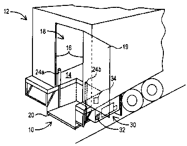
[0023] Refen-ing to FIG. 1, an elevator delivery system 10, according to one
embodiment of the
present invention, is located in a truck body 12 for moving cargo relative to
the bed 14 of the
truck body i2. As used herein, the term "truck body" refers to both a non-
detachable truck body
and detachable truck body (e.g., trailer}. In the exemplary embodiment, the
elevator delivery
system 10 is located between the walls 16 forming the rear doorway 18, which
is accessible by
opening the door 19. A portion of the exemplary elevator delivery system 10
extends beyond the
walls 16 outside of the truck body 12. Alternatively, the elevator delivery
system 10 can be
located at a side doorway or any other suitable location in the truck body 12.
[0024] Referring to FIG. 2, the elevator delivery system 10 comprises a
platform 20 and at least
two hydraulic cylinder/piston mechanisms 24a, 24b. Each of the hydraulic
cylinder/pistan
mechanisms 24a, 24b includes a piston 26a, 26b mounted to the platform 20 and
a cylinder 28a,
28b mounted to the truck body 12 such that movement of the pistons 26a, 26b
relative to the
cylinders 28a, 28b causes movement of the platform 20 relative to the truck
body I2. The
pistons 26a, 26b and cylinders 28a, 28b can be mounted using any known
techniques (e.g., by
using plates or other fixtures welded to the platform 20 and the truck body
12). In the exemplary
embodiment, the pistons 26a, 2tSb are mounted at opposite sides of the
platform 20. Although
the pistons 26a, 26b are shown mounted generally at a midpoint of the platform
20, the pistons
26a, 26b can be mounted in other locations on the platform 20. Iii the
exemplary embodiment,
the cylinders 28a, 28b are mounted to the bed 14 of the truck body 12. The
cylinders 28a, 28b
can also be mounted to other locations, such as to the walls 16 (see FIG. I )
of the truck body 12.
In a further embodiment (not shown), the cylinders 28a, 2tib can be located
within the walls 16
of the truck body 12; thereby hiding the cylinders 28a, 28b and avoiding
interference with the
cargo.
[0025] A hydraulic control system 30, described in greater detail below,
controls the supply of
fluid to the hydraulic cylinder/piston mechanisms 24a, 24b and thus contxols
the movement of
the platform 20. The hydraulic control system 30 is preferably actuated fiom
both inside and
outside the truck body 12. For example, an outside up/down switch 32 is
located outside of the
thick body 12 to allow the user to raise and/or lower the platform 20 from
outside of the truck
body 12. The outside switch 32 is preferably in a location that keeps the user
away from the
CA 02486010 2004-10-28
platform 20 when it is being lowered. An inside upldown switch 34 is located
inside the truck
body io allow the user to raise and/or lower the platform 20 from inside the
truck body 12, for '
example, when standing on the platform 20. Although the exemplary embodiment
shows the
hydraulic control system 30 in a location outside of and below the truck body
12, the hydraulic
control system 30 can be located in other locations inside or outside of the
truck body 12.
[0026] The cylinders 28a, 28b are coupled to the hydraulic control system 30
by way of
hydraulic lines 40a, 40b. The hydraulic lines 40a, 40b are preferably in a
location that will not
interfere with loading and unloading cargo (e.g., under the truck bod 14). The
outside switch 32
and the inside switch 34 are connected to the hydraulic control system 30 by
way of wires 42, 44,
respectively. Other connections between the hydraulic control system 30 and
the cylinders 28a,
28b and the switches 32, 34 are also contemplated.
[0027) In one preferred embodiment, an edge switch 50 is locatod around the
edge of the
underside of the truck body 12 adjacent to the path of the moving platform 20.
The edge switch
50 is connected to the hydraulic control system 30 by way of wire 52. The edge
switch 50
provides an added safety feature when the platform 20 is being raised. If an
object, such as the
cargo or the driver's foot, is positioned between the platform 20 and the
underside of the truck
body 12 when the platform 20 is being raised, the object. will actuate the
edge switch 50.
Actuation of the edge switch 50 causes the hydraulic coatrol system 30 to
preferably move the
platform 20 downward to avoid damage or injury.
[0028] In another preferred embodiment, an audible alarm 54 alerts the
operator that the
platform 20 is being raised sndlor lowered. The audible alarm 54 can be
connected to the
hydraulic control system 30 and located in any location that permits the alarm
to be heard near
the elevator delivery system 10.
[OOZ9) One embodiment of the truck body 12 preferably includes bracing 60
surrounding the
platform region 62, which receives the platform 20 in the raised position. A
lower portion b4 of
the bracing 60 is preferably tapered such that an object (e.g., the driver's
toe) that comes into
contact with the tapered lower portion 64 will slide out of the way to avoid
damage or injury. In
this embodiment, the edge switch 50 is located beneath the tapered lower
portion 64 of the
bracing 60. A rubber seal (not shown) can be provided along tire top portion
of the bracing 60
to seal against the platform 20 when raised. One embodiment of the platform 20
includes a ramp
surface 6S at one side to allow cargo to be more easily wheeled off of the
platform 20.
.,
CA 02486010 2004-10-28
(0030] Referring to FIG. 3, an exemplary embodiment of the elevator delivery
system I O is
shown schematically. In the exemplary embodiment, the truck body 12 includes
8" structural '
steel channels forming the bracing 60. The exemplary hydraulic cylinders 28a,
28b supported on
the channels are single acting hydraulic cylinders having a bore of about 2
%z" and a length of
about 77". The tapered lower portion.64 of the bracing 60 is a formed as a
section having a
width of about 5" flared out at about 45° under the channels. The
exemplary platform 20 is
made of 1" steel having a dimension of about 48" by 44" and having a 2" by 2"
bracing.
(0031] Referring to FIG. 4, an exemplary embodiment of the hydraulic control
system 30 is
shown schematically. According to this embodiment, the hydraulic control
system 30 includes
an electric hydraulic pump 72 with an electric solenoid 74 and a dump valve
?6. In one example,
the pump 72 is a pump having a rating of about 2500 psi, such as the type
available under the
name Monarch from Monarch Hydraulics. The wires 42, 44 connect the solenoid 74
to the
outside switch 32 and the inside switch 34 (see FIG. 2), respectively, and the
wire 52 connects
the dump valve 76 to the edge switch.50. The wire 88 connects the electric
hydraulic pump 72 to
a power souses such as the vehicle battery (not shown). The pump 72 is
connected to a tank 80
(e.g., a 3 gallon tank) that supplies hydraulic fluid to the pump 72. A flow
divider valve 82 is
connected to the pump 72 by way of a hydraulic line 84 and connects the pump
72 to the
hydraulic lines 40a, 40b from the cylinders 28a, 28b. The hydraulic control
system 30 is
preferably housed in an enclosure 86 that protects and allows access to the
hydraulic control
system 30.
[0032] In response to signals from the up/down switches 32, 34, the solenoid
74 actuates the
pump 72 to pump hydraulic fluid through the lines 40a, 40b to or from the
hydraulic cylinders
28a, 28b to lower or raise the platform 20. The flow divider valve 82 evenly
distributes the
hydraulic fluid pressure between the hydraulic cylinders 28a, 28b to maintain
the platform 20 in
a substantially level position when a load is being raised or lowered, thereby
preventing the
hydraulic cylinder/piston mechanisms 24a, 24b from binding. In response to the
edge switch 50,
the dump valve 76 is actuated causing the platform 20 to drop. In one
embodiment, the elevator
delivery system 10 at a back door of the truck body is capable of lifting
about 2500 lbs. or more
and the elevator delivery system 10 at a side door of the truck body is
capable of lifting about
1500 lbs. or more, although this is not a limitation of the present invention.
CA 02486010 2004-10-28
[0033] In use, the platform 20 can be raised or lowered using either the
outside switch 32 or the
inside switch 34. Referring to FIGS. SA-SC, one method of using the elevator
delivery system '
is described in greater detail. At the beginning of a delivery, the driver 92
can open the door
19 and drop the platform 20, for example, using the outside switch 32 (FIG.
5A). The driver 92
can then ride up on the platform 20 into the truck body 12 (using the inside
switch 34) to load the
cargo 90 onto the platform 20 (FIG. SB). When the platform 20 is loaded with
the cargo 90, the
driver 92 can lower the platform 20 and the cargo 90, for example, using the
inside switch 34
(FIG. 5C). This process can be repeated until the delivery is completed. Thus,
the driver 92 can
use the elevator delivery system 20 to avoid having to climb in and~out of the
truck when making
deliveries.
[0034] Accordingly, the elevator delivery system 10 is relatively easy to
opiate compared to
existing devices and thus facilitates the unloading and loading of cargo into
a truck or trailer.
The elevator delivery system 10 also has fewver moving parts and thus operates
more efficiently
and reliably than existing hydraulic tailgate and lift devices. The elevator
delivery system 10
further provides a number of additional safety features to avoid injury to the
operator. For
example, the location of the inside switch and the outside switch 32, the edge
switch 50, and the
audible alarm 54 all provide safety features that will minimize injuries
caused by using the
elevator delivery system 10.
[0035] Referring to.FIGS. b-12, a further embodiment of an elevator delivery
system 110 used in
a truck body 112 is described in greater detail. This embodiment of the
elevator delivery system
110 includes a platform 120 that moves between as exteaded position shown in
FIG. 6 and an
upright position shown in FIG. 8. In the upright position, the platform 120 is
positioned betwtar
the walls 116 of the truck body 112 and preferably flush with the walls 116.
When the platform
120 is moved to the extended position, the platform 120 extends outward from
the truck bed 114
for loading. When in the extended position, the platform 120 can be moved
between a raised
position (FIG. 6) and a lowered position (FIG. 9).
[0036] The platform 120 is coupled to a drive mechanism 124 (FIG. 7), such as
a hydraulic
cylinderlpiston mechanism including a piston 126 and cylinder 128 on each side
of the platform
120 to move the platform 120 between the raised position and the lowered
position. The
hydraulic cylinders 128 can be similar to those described above but are
preferably double acting
hydraulic cylinders capable of hydraulically moving the platform 120 downward
as well as
CA 02486010 2004-10-28
8
upward. The exemplary embodiment of the elevator delivery system 110 also
includes a
hydraulic coimol system (not shown) similar to that disclosed above but
preferably with two '
flow dividers to provide the downward. hydraulic movement in addition to
upward movement.
The elevator delivery system 110 can also include the switches and other
features similar to
those described above in connection with other embodiments.
[0037] The platform 120 is preferably coupled to the pistons 126 in a manner
that allows the
platform 120 to pivot between the upright and extended positions, as shown in
FIGS. 10-12. In
the exemplary embodiment, a shaft 102 extends through the platform 120 and is
coupled at each
end to the pistons 126 using brackets 104, 105 or other coupling devices known
to those skilled
in the art. Rallcr bearings 106,108 are mounted to the platform 120 and are
rotatably mounted
on the shaft 102, allowing the platform 120 to pivot from the upright position
to the extended
position (FIG. I2). The platform 120 preferably includes a Stop tab 150 that
abuts a hard stop
bar 152 or other rigid structure to maintain the platform 120 substantially
horizontal in the
extended position (FIG. 12). The platform 120 can also include a reinforcement
bracket i 54 to
provide additional reinforcement in the middle region of the platform 120.
[0038] In one example, the platform 120 is made of aluminum and is about 44"
by 32". Other
materials and sizes are also contemplated. Where the platform 120 is made of a
light-weight
material such as aluminum, the drive mechanism 124 preferably moves the
platform 120
downward. Where the platform 120 is made of a heavier material, gravity can
move the platform
120 downward without being driven by the drive mechanism 124.
[0039] The elevator delivery system 110 fiuther includes foldable side rails
I30 coupled between
sides of the platform I20 and the walls 116 of the truck body, as a safety
feature. The foldable
side rails 130 include a first folding side bar 132 pivotably coupled to the
side of the platform
120 and a second folding side bar 134 pivotably coupled to the first folding
side bar 132, The
second folding side bar 134 is pivotably coupled to a sliding bar 136. The
sliding bar 136 can
move freely or can be slidably mounted to the wall 116. In ono ~cample, the
bars 132, 134 are
flat bars made of steel. A chain or other similar structure (not shown) can be
coupled between
the foldable side rails 130 to provide an additional safety feature acmss the
front of the platform
120.
[0040] In the exemplary embodiment, the elevator delivery system 110 is
located in a side
doorway I 18 of a truck body 112, although other locations arc contemplated.
Because the
CA 02486010 2004-10-28
platform 120 does not form part of the floor of the truck bed 114, the
elevator delivery system
110 can be operated without interfering with pallets or other cargo stacked at
the doorway, '
(0041] Modifications and substitutions by one of ordinary skill in the art are
considered to be within
the scope of the present invention, which is not to be limited excopt by the
following claims.