Note: Descriptions are shown in the official language in which they were submitted.
CA 02486085 2004-11-15
WO 03/097459 PCT/IB03/01934
-1-
UNIT FOR FILLING CONTAINERS WITH PRODUCTS, IN PARTICULAR,
PHARMACEUTICAL PRODUCTS
FIELD OF THE INVENTION
The present invention relates to automated packaging of
small products into containers.
In particular, the invention relates to a unit for
continuously feeding and counting such products, mainly
pharmaceutical products, such as tablets, pills or
capsules for pharmaceutical use, from now on called
simply pharmaceutical tablets without losing the
universality, and for subsequently introducing the
pharmaceutical tablets into bottles or the like.
BACKGROUND OF THE INVENTION
In the pharmaceutical production field, there are
commonly known and used packaging machines for automatic
packaging of pharmaceutical tablets supplied in bulk into
bottles.
Usually, a packaging machine of known type includes
several working groups, among which, in particular, there
are a device for orderly feeding and counting tablets,
preferably performing a tablet quality check, and a
device for filling the bottles, moving stepwise on a
conveyor, with a predetermined number of tablets.
There are several types of packaging machines for
automatic packaging pharmaceutical tablets into bottles,
types which differ mainly by the techniques used for
orderly feeding and counting the tablets.
CA 02486085 2004-11-15
WO 03/097459 PCT/IB03/01934
-2-
A packaging machine belonging to a first type includes a
feeding and counting device formed by a series of small
bars arranged one beside another, crosswise with respect
to the conveying direction and featuring a plurality of
seats, each of which receives a single tablet.
The above small bars are carried along the conveying
direction below a hopper, which contains a mass of
tablets in bulk, so that each seat can receive a single
tablet.
The small bars are then moved toward a discharge station,
where the tablets are released into the bottles, by the
effect of gravity, making fall one or more tablets from
one of the small bars into each bottle suitably arranged
on the conveyor below the hopper.
Thus, the number of seats of each small bar defines the
maximum number of bottles, which can be filled
simultaneously.
The machines of the above described type reach
considerable operation speed (even 300-400 bottles filled
'20 in a minute), however they present many limits and
drawbacks.
First of all,. the seats of the small bars are not always
correctly filled during the passage below the hopper,
because the tablets of irregular shape can be arranged in
an incorrect position with respect to the relative seat,
or some seats can be occupied'by tablet fragments or by a
non entire tablet.
Therefore, it can quite easily happen that a bottle is
filled in an incomplete, or incorrect way.
Moreover, if a defective or partially damaged tablet is
detected, the above described machines are not able to
CA 02486085 2004-11-15
WO 03/097459 PCT/IB03/01934
-3-
reject a single defective table and therefore it is
necessary to reject the whole bottle containing the
defective tablet, which obviously results in considerable
economic consequences.
Further drawbacks result from the complexity of the size
change over operations in order to adapt the machine to
operate with tablets and/or bottles of different sizes,
since in order to work with each different type or size
of tablets or capsules, it is necessary to substitute the
whole group of the small bars.
Another known type includes packaging machines featuring
a plurality of rotating discs arranged one beside another
along their axis.
Each disc is driven into rotation independently from the
others and features, along its circumference, a number of
seats for receiving-therein the tablets to be packaged.
A hopper containing a mass of tablets in bulk is situated
directly above the plurality of discs.
During rotation, each disc withdraws single tablets, one
by one, from the hopper.
The disc rotation brings each tablet to an instability
point, and consequently makes it fall into a bottle
situated below.
During this step, each tablet can be counted and its
entireness can be checked by suitable check devices.
Although the above described packaging machines with
discs are very fast and reliable at the tablets counting,
they require the substitution of the whole group of discs
each time the size -and/or the shape of the tablets to be
packaged is changed.
CA 02486085 2004-11-15
WO 03/097459 PCT/IB03/01934
-4-
This makes the use of this type of machines particularly
expensive if there are several sizes of the tablet to be
packaged.
A known packaging machine of a further type includes a
plurality of vibrating planes arranged in succession
along the conveying path of the tablets to be packaged.
The tablets are continuously fed to the vibrating planes
from a hopper, and then they are gradually spaced apart
and conveyed toward a counting area, at the outlet of the
vibrating planes.
The vibrating planes are usually equipped with
longitudinal guides, arranged one beside another and
containing each one a row of tablets.
Each tablet is counted at the outlet of the relative
guide by photo-cell or capacitive sensors, generally
during its fall into a channel conveying it toward the
bottle to be filled.
The number of longitudinal guides situated one beside
another defines the number of bottles which can be filled
simultaneously.
The structure of this type of machine is usually simple
and easy to maintain.
Also the size change over operations are rather simple.
On the other hand, their production rate is rather
limited and not always the spacing of the tablets in the
area of the outlet of the vibrating planes is optimal.
This results in considerable problems in tablets counting
and checking of their entireness
In a packaging machine of another known type, such e.g.
the one described in the US Patent 5.463.839, the tablets
CA 02486085 2004-11-15
WO 03/097459 PCT/IB03/01934
-5-
to be packaged are carried by a hopper on an inclined
plane equipped with a series of channels, arranged side
by side, each of which receives single tablets, one by
one.
The inclined plane moves the tablets toward a counting
and packaging area.
The above channels have undulated extension, and the
undulation amplitude is gradually decreasing.
Therefore, the tablets move faster and faster, coming
close to the counting area and thus they are spaced
apart, or singled out, so as to be counted during the
descent into the bottles.
Also the structure of the last packaging machine is very
simple, but it presents considerable drawbacks, first of
all in the spacing apart of elongated or oblong tablets,
since the oblong tablets can easily stick or take a
crosswise position in the undulated channels, thus
causing the channels obstruction, which results in an
incorrect feeding and consequently filling of bottles.
SUMMARY OF THE INVENTION
The object of the present invention is to propose a unit
for feeding pharmaceutical tablets to bottles, which
avoids the above mentioned drawbacks of the prior art.
In particular, an object of the present invention is to
propose a unit, which ensures a rapid and safe feeding of
the tablets to be packaged to the counting area, keeping
a simple structure, which is easily accessible for
maintenance operations.
Another object of the present invention is to propose a
unit, which can efficiently move away and single out the
CA 02486085 2004-11-15
WO 03/097459 PCT/IB03/01934
-6-
tablets, in order to allow particularly reliable
operations of tablets counting and entireness checking.
A further object of. the present invention is to propose a
unit, which rejects single defective tablets.
A still further object of the present invention is to
propose a packaging machine, which is equipped with the
above unit, and which operates easily with products of
different sizes, thus requiring a reduced number of
elements to be replaced during the size change over.
According to the present invention, a unit for filling
containers with products, in particular pharmaceutical
products, includes a hopper containing a mass of products
in bulk, conveying means aimed at feeding the products,
coming out of the hopper, along a predetermined path up
to a station where the containers are filled with the
products, said containers being fed to said filling
station by transporting means; and a product checking
station, situated along said path upstream of said
filling s-ration; the unit being characterized in that
said conveying means include:
first conveying means consisting of vibrating planes;
second conveying means situated at said checking station
between said conveying vibrating planes means and said
filling station; and
product holding means associated to said second conveying
means for keeping single products, so as to form, on said
second conveying means a succession of single spaced
apart products, moving forward to said filling station
along a part of said path.
CA 02486085 2010-07-09
- 7 -
The second conveying means preferably include a rotating
drum, aimed at moving the successions of single products
to the filling station, along a curved part of the path.
In one aspect, the invention provides a unit for
filling containers with products, the unit comprising:
a hopper for containing a mass of products in bulk;
conveying means for feeding said products coming out
of said hopper along a predetermined path;
a filling station, situated downstream of said
conveying means for filling said containers with the
products;
transporting means for feeding said container to
said filling station; and
a station for checking said products, situated along
said path upstream of said filling station;
said conveying means including first conveying means
consisting of vibrating planes and second conveying
means situated at said checking station between said
conveying vibrating planes means and said filling
station, said second conveying means include a drum
rotating continuously, which moves said series of
single products to said filling station 'along a curved
portion of said path;
said conveying means further including product
holding means associated to said second conveying
means for keeping single products, so as to form, on
said second conveying means a succession of single
spaced apart products, moving forward to said filling
station along a part of said path, wherein the whole
peripheral surface of the drum features a plurality of
grooves, each of which has lateral walls converging
toward the bottom of the groove in order to receive
the products released by said vibrating planes.
CA 02486085 2010-07-09
- 7a -
BRIEF DESCRIPTION OF THE DRAWINGS
The characteristic features of the invention, as will
appear from the subsequent claims, are pointed out in the
following description of a preferred, but not limiting
embodiment of the invention with reference to the
enclosed drawings, in which:
- Figure 1 is a schematic lateral view, partially in
section and with some parts removed for sake of
clarity, of a preferred embodiment of the unit
proposed by the present invention;
- Figure 2 is a schematic top view of the unit of
Figure 1;
- Figure 3a is a lateral section view of some working
stations of the unit of Figure 1;
- Figure 3b is the same lateral section view as Figure
3a view, with a functional variant;
- Figure 4 is a cross-section view of an alternative
embodiment of a particular of the unit of Figure 1;
and
- Figure S is a section view taken along the section
V-V of Figure,3a.
BEST MODES OF CARRYING OUT THE INVENTION
CA 02486085 2004-11-15
WO 03/097459 PCT/IB03/01934
-8-
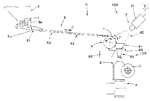
With reference to Figures 1 and 2, the reference
indication M stands for a machine packaging
pharmaceutical tablets 1 into corresponding bottles 2.
The tablets 1 are moved forward to a filling station R on
a carrier 4 by a feed screw C operated discontinuously.
The reference numeral 100 indicates a unit for feeding
and counting the tablets 1, which unit is an integral
part of the packaging machine M.
According to what has been shown in Figure 1, the unit
100 includes a feeding hopper 3, containing a mass of
tablets 1 in bulk and equipped with a lower mouth 3a,
through which the tablets 1 exit due to gravity force.
The lower mouth 3a is provided with a relative closing
shutter 3b.
In particular, according to a preferred embodiment, the
hopper 3 is equipped with three outlet mouths 3a with
relative shutters 3b, which move in such a way as to
allow, when in use, to automatically adjust the outlet
flow of the tablets 1, in order to regularly space them
apart.
According to what has been shown in Figures 1 and 2, the
unit 100 includes a conveyor 5, which receives
continuously the tablets 1 falling from the hopper 3 and
arranges them substantially in parallel rows, so as to
carry them to the filling station SR in a direction D
defined crosswise with respect to the forward movement
direction of the bottles 2 on the carrier conveyor 4.
The conveyor 5 is supported by a structure, which has not
been shown in Figure 1 and which is a part of the machine
M.
CA 02486085 2004-11-15
WO 03/097459 PCT/IB03/01934
-9-
The structure includes preferably, but not only, three
vibrating conveying planes 51, 52 and 53, driven to
vibrate by vibrating means, known and not shown.
The vibrating planes are arranged one after another and
are slightly inclined downwards in the direction D.
More precisely, the vibrating plane 51 situated upstream
is arranged with its initial portion directly below the
outlet mouth 3a of the hopper 3, the intermediate
vibrating plane 52 is situated downstream of the plane
51, and the vibrating plane 53 is situated downstream of
the intermediate plane 52.
As it is seen in Figure 1, the initial portion of the
vibrating planes situated more downstream in the
direction D lies below the terminal portion of the plane
situated directly upstream, still in direction D.
As seen in Figure 2, each vibrating plane 51, 52, 53 is
equipped with a plurality of longitudinal guides - 541
situated one beside another and parallel to one another.
Each guide 54 is aimed at receiving and conveying, one by
one, the tablets 1 in a single row, and presents lateral
walls 54a, 54b converging toward the bottom of the guides
54 (see Figure 4).
Essentially, as it is possible to see in Figure 4, each
guide 54 has preferably a substantially up-turned
triangle cross-section, with the base open and the vertex
turned downwards.
According to a not shown variant, the guides 54 have
substantially U-section.
This, together with the continuous vibration effect,
allows to obtain a well determined arrangement of the
tablets 1.
CA 02486085 2004-11-15
WO 03/097459 PCT/IB03/01934
-10-
In particular, in case of substantially discoid tablets
(Figure 3a), they tend to lean against a lateral wall
54a, 54b, while in case of elongated or oblong tablets 1
(Figure 3b), they tend to assume a position with their
main axis oriented longitudinally with respect to the
relevant guide 54.
The guides 54 of the subsequent vibrating planes 51, 52,
53 are aligned with respect to each other, so that each
of them can receive tablets 1 leaving the plane situated
more upstream.
The unit 100 includes also another conveyor 6, consisting
of a rotating drum, which is situated directly
downstream, in the direction D, of the conveyor 5 and
extends along the whole crosswise extension of the
conveyor 5.
The rotating drum conveyor' 6 is aimed at rotating
continuously clockwise in direction W, with respect to
Figure 1, with a determined angular speed, so as to feed
the tablets 1 along a feeding path P up to the station
SR, where the bottles 2 are filled. The curved section of
the feeding path P is substantially defined by the edge
of the drum 6.
According to what is shown in Figures 2, 3a and 3b, the
drum 6 is-arranged with the upper part of its peripheral
surface situated directly below the outlet portion of the
fore vibrating plane 53.
The cylindrical peripheral surface of the drum 6,
according to the preferred embodiment shown in Figures 1,
3a and 3b, is substantially smooth.
Otherwise, like in the alternative embodiment shown in
Figure 4, the whole peripheral surface of the drum 6
features a plurality of grooves 64, each of which has
CA 02486085 2004-11-15
WO 03/097459 PCT/IB03/01934
-11-
lateral walls 64a, 64b converging toward the bottom of
the groove 64 and with a substantially up-turned triangle
conformation, like the walls 53a, 53b of each guide 54 of
the plane 53, in order to receive the tablets 1 released
by the corresponding guide 54.
The drum 6 includes also holding means 65, which act to
hold the tablets 1 on the surface of the drum 6, in
particular within the grooves 64, according to the
embodiment shown in Figure 4.
The holding means 65 include a plurality of channels 66,
67, 68, situated inside the drum 6.
The channels 66, 67, 68 (Figures 3a, 3b) are aimed at
setting the surface of the drum 6 in communication with a
vacuum source, known and not shown, which creates an
aspiration effect at the drum surface, so as to hold the
tablets 1 by aspiration.
-In particular, the peripheral surface of the drum 6
features a plurality of channels 66 (plurality of pairs
of channels 66 in Figures 3a, 3b), opening close to each
other, so that even =a small tablet 1 is anyway situated
within the action range of the depression created by at
least one of the channels 66, and is therefore held by
the aspiration of the drum 6.
According to what has been shown better in Figure 1, the
curve section of the path P, covered by the tablets
conveyed by the drum 6, extends passing through a
checking station SC, where the unit 100 includes checking
means 7 aimed at acquiring information concerning the
tablets 1 during their movement toward the station SR.
This information relates in particular to the detection
of the passage of each tablet 1 in a predetermined point,
possibly also to the detection of some characteristics,
CA 02486085 2004-11-15
WO 03/097459 PCT/IB03/01934
-12-
such as shape, color or others, necessary to evaluate the
integrity of the examined tablet and to perform a precise
counting of the tablets 1 passing through the station SC
along the path P.
In order to perform the above detection in an efficient
and optimal way, the checking means 7 include preferably
a videocamera or telecamera 71, whose optical path is
oriented toward the drum 6, so that it can see the whole
extension of the drum 6.
The videocamera 71 is also connected, in a wholly known
way, to a processing device E, in order to send the
latter the signals related to detections effected. Thus,
the signals can be suitably processed.
According to what has been shown in Figures 3a and 3b,
the unit 100 includes also deflector means 8, which are
situated near the drum 6, downstream of the check station
SC and upstream of the filling station SR, and which
detach the tablets 1 from the drum 6, so that the tablets
fall into-'corresponding packaging channels 9.
The deflector means 8 include a plurality of deflecting
bars 81, situated one beside another.
Each bar 81 is pivoted onto a pin 82 and is aimed at
being moved by operating means, not shown, which are
connected to the processing device E, alternately between
a detach position A, in which the free end of the bar 81
intercepts and detaches the tablets 1 conveyed by the
drum 6, and tablets rejection position B (indicated with
broken line in Figures 3a and 3b), in which the bar 81 is
situated far from the drum 6 surface, so that the tablets
1, found defective by the videocamera 71 and held on the
drum 6, are moved forward to a subsequent rejection
station, where the defective tablets 1 are detached from
CA 02486085 2004-11-15
WO 03/097459 PCT/IB03/01934
-13-
the drum 6 by a motionless deflecting panel 85 and fall
into a rejection container 86.
Each of the above mentioned packaging channels 9 includes
an upper housing 91, whose outlet mouth communicates with
an inlet mouth of a lower housing 92, which in turn, has
an outlet mouth situated above a bottle 2 (Figure 1).
According to what has been shown in Figures 3a, 3b, a
bulkhead 93 is situated between the upper housing 91 and
the lower housing 92.
The bulkhead 93 is moved alternately by activating means,
not shown and operated by the processing device E,
between a position, in which the outlet mouth of the
upper housing 91 is closed, and a position, in which the
same outlet mouth is open.
The operation of the unit 100 is described in the
following, beginning from an operation condition in which
a mass of tablets 1 is present in bulk within the hopper
3, and the bottles 2 to be filled have been brought on
the transporting conveyor 4, by the feed screw C, to the
filling station SR.
The vibrating planes 51, 52, 53, are operated, that is
the vibrating means are activated, and the drum 6 is
driven into rotation in the direction W.,
Therefore, the vibration of the planes 51, 52, 53 creates
a gradual forward movement of the tablets 1 along each
guide 54 of the vibrating planes, toward and at the drum
6.
According to another, not shown, embodiment, each
vibrating plane 51 is connected to two vibrating means,
applied to the opposite lateral ends of the plane 51, in
order to ensure that the best uniform distribution of the
CA 02486085 2004-11-15
WO 03/097459 PCT/IB03/01934
-14-
tablets 1 can reach, through other planes 52 and 53, the
drum 6, thus preventing the drum 6 from being not
perfectly and not uniformly loaded with the tablets 1.
When the tablets 1 are released by the guides 54, due to
the conformation thereof, they are arranged in a well
defined way; thus the tablets 1 fall and reach the
peripheral surface of the drum 6 and are held by the
suction present in the channels 66.
In particular, the angular speed of the drum 6 is
suitably and automatically adjusted, so that two tablets
1 situated one after another, are spaced apart (that is
singled out) in best way.
In the check station SC, each tablet 1 is perfectly
detected by the telecamera 71, and then its integrity is
verified.
Each tablet 1, if considered perfectly entire, is then
intercepted by the, deflecting bar 81, situated in the
detachment position A, due to the command of the
processor-E, which has received a suitable signal from
the videocamera 71.
Afterwards, the intercepted tablet 1 is conveyed toward
the corresponding packaging channel 9.
In operation, if a bottle 2 being filled is present under
the channel 9, the bulkhead 93 is kept open due to the
command of the processor E, in function to the
information of the telecamera 71, and the tablet
lproceeds toward the bottle 2, taking place thereinside.
Otherwise, if there is no bottle 2, because the feed
screw C is bringing a subsequent group of empty bottles
to the station SR and on the conveyor 4, the bulkhead 93
is close, still due to the command of the processor E,
CA 02486085 2004-11-15
WO 03/097459 PCT/IB03/01934
-15-
which has received a suitable signal from the telecamera
71, and the tablets 1 are accumulated in the upper
housing 91 until a new bottle 2 is available.
When this occurs, the bulkhead 93 is open again to allow
the tablets 1 present in the housing 91 to go down.
When the counting of the tablets 1 by the telecamera 71
reaches a predetermined and memorized value, that is when
the bottle 2 is considered filled with tablets 1, the
bulkhead 93 is closed again, still due to the command of
the processor E, which has received an information signal
from the telecamera 71, concerning the full bottle 2.
If the telecamera 71 considers a tablet 1 defective
and/or not entire or anyway, faulty (indicated with
broken line in Figures 3a and 3b), the corresponding
deflecting bar 81 is brought to the rejection position B,
due to the command of the processor E, and thus the
defective tablet 1 is conveyed by the drum 6 until it is
intercepted by the motionless deflecting panel 85 and
conveyed into the container 86 of tablets 1 to be
rejected.
One of the important advantages of the above described
unit 100 for feeding and counting tablets 1 is that it
ensures a rapid and secure transport, without jamming of
single tablets 1 to be packaged, toward the checking
station SC and the subsequent filling station SR,
maintaining a simple structure of the packaging machine
M.
Another advantage derives from an efficient spacing or
separation of the adjacent tablets 1 in the check station
SC due to the efficient presence of the sucked drum 6
below the vibrating plane 53, which allows particularly
rapid and efficient counting and optical check of
CA 02486085 2004-11-15
WO 03/097459 PCT/IB03/01934
-16-
entireness of the tablets 1 by the telecamera 71, without
possibility of error.
A further advantage of the unit 100 lies in the
possibility to work with different sizes and dimensions
of tablets 1, which consequently requires a reduced
number of elements substitution and downtimes of the
packaging machine M, of which the unit 100 is a part.
Actually, the conformation of the guides 54, as well as
the presence of the system for maintaining the drum 6
surface in suction condition, allows to use the same
elements for tablets 1 having even very different sizes
and dimensions.
Moreover, the unit 100 proposed by the present invention,
due to the system of deflecting bars 81 operated to move
by the processor E consequently to the signal of the
telecamera 71, allows rejection of single tablets 1
considered defective, without the necessity to reject the
whole bottles 2 because of the presence of only one
faulty tablet 1, as it occurs in the currently used
packaging machines.
Moreover, the presence of the bulkhead 93 closing the
channels 9 allows to continue the feeding, without
interruptions, of the tablets 1 even if there are no
bottles 2 in the filling station SR, that is in the
moments subsequent to the exit of a group 2 of full
bottles from the station SR and before a new group of
bottles 2 to be filled arrives.
Therefore, the packaging machine M can work with very
high working speed.