Language selection

Search

Patent 2486384 Summary

Third-party information liability

Some of the information on this Web page has been provided by external sources. The Government of Canada is not responsible for the accuracy, reliability or currency of the information supplied by external sources. Users wishing to rely upon this information should consult directly with the source of the information. Content provided by external sources is not subject to official languages, privacy and accessibility requirements.

Claims and Abstract availability

Any discrepancies in the text and image of the Claims and Abstract are due to differing posting times. Text of the Claims and Abstract are posted:

  • At the time the application is open to public inspection;
  • At the time of issue of the patent (grant).
(12) Patent Application: (11) CA 2486384
(54) English Title: FIRE PREVENTION FENCE
(54) French Title: CLOTURE DE PREVENTION D'INCENDIE
Status: Deemed Abandoned and Beyond the Period of Reinstatement - Pending Response to Notice of Disregarded Communication
Bibliographic Data
(51) International Patent Classification (IPC):
  • A62C 02/00 (2006.01)
  • A62C 03/02 (2006.01)
  • A62C 37/11 (2006.01)
  • E04H 17/00 (2006.01)
(72) Inventors :
  • TREDDENICK, GEORGE A. (Canada)
(73) Owners :
  • GEORGE A. TREDDENICK
(71) Applicants :
  • GEORGE A. TREDDENICK (Canada)
(74) Agent: BATTISON WILLIAMS DUPUIS
(74) Associate agent:
(45) Issued:
(22) Filed Date: 2004-10-25
(41) Open to Public Inspection: 2005-04-27
Examination requested: 2009-10-01
Availability of licence: N/A
Dedicated to the Public: N/A
(25) Language of filing: English

Patent Cooperation Treaty (PCT): No

(30) Application Priority Data:
Application No. Country/Territory Date
60/513,986 (United States of America) 2003-10-27

Abstracts

English Abstract


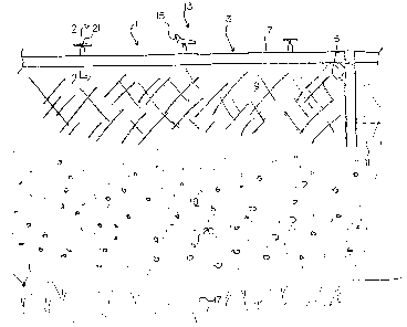
A fire prevention apparatus includes a fence to surround an area to be
protected where a top rail of the fence defines a pipe for a sprinkler system
such that
a water supply can be pumped to provide water to the sprinkler system which is
controlled to provide pressure for regularly spraying the area along the fence
with
herbicides to control vegetation and underbrush and when required to provide
pressure to the system when heat is detected by a sensor such that the
sprinkler
system applies water to the area to suppress an approaching fire.


Claims

Note: Claims are shown in the official language in which they were submitted.


6
CLAIMS:
1. A fire prevention apparatus comprising:
a fence arrangement arranged to surround an area to be
protected;
a sprinkler system incorporated on the fence arrangement;
a water supply arranged to provide water to the sprinkler
system;
a control arrangement arranged for controlling the flow of water
to the sprinkler system;
the control arrangement being arranged to provide pressure to
the system for regularly spraying the area along the fence with herbicides to
control
vegetation and underbrush;
the control arrangement being arranged to provide pressure to
the system when heat is detected by a sensor such that the sprinkler system
applies
water to the area to suppress an approaching fire.
2. The apparatus according to Claim 1 wherein the fence
arrangement includes a top rail which forms a pipe for the sprinkler system.
3. The apparatus according to Claim 1 wherein the sprinkler
system includes a supply tank and an injector for adding materials to the
water to be
sprayed.
4. The apparatus according to Claim 1 wherein the sprinkler
system includes a first set of nozzles for spraying herbicide to inhibit
vegetation on
either side of the fence and a second set of nozzles for spraying water for
dousing a

7
fire adjacent the fence.

Description

Note: Descriptions are shown in the official language in which they were submitted.


CA 02486384 2004-10-25
FIRE PREVENTION FENCE
FIELD OF THE INVENTION
The present invention relates to a fire prevention fence arranged to
provide a fire break surrounding a protected area.
BACKGROUND
In areas of high fire risk it is important to protect residential buildings,
commercial buildings are well as buildings that are isolated. Also, areas such
as
towers and the like can be located in areas that have high fire risks. These
areas
may sometimes be overgrown with underbrush which can cause a fire to spread
quickly. When fighting such fires, it is important to provide the area with a
fire break
which prohibits a fire from spreading.
US Patent 6,450,264 (Christian) is a sprinkler system arranged to be
mounted onto a house to prevent brush and forest fires from engulfing the
home.
The sprinkler system is mounted directly onto the home but does not
particularly
provide a fire break between the home and the fire.
US Patent 3,425,630 (Fessler) discloses a sprinkler system mounted
onto a fence. The system is primarily used for irrigation and the patent does
not
mention using the system for providing a fire break and does not disclose any
method of doing so.
SUMMARY
According to the present invention there is provided a fire prevention
apparatus comprises:
a fence arrangement being arranged to surround an area to be

CA 02486384 2004-10-25
2
protected;
a sprinkler system incorporated within the fence arrangement;
a water supply arranged to provide water to the sprinkler system;
a control arrangement being arranged for controlling the flow of water
to the sprinkler system;
the control arrangement providing pressure to the system for regularly
spraying the area along the fence with herbicides to control vegetation and
under
brush;
the control arrangement providing pressure to the system when heat is
detected by a sensor such that the sprinkler system applies water to the area
to
suppress an approaching fire.
Preferably the fence arrangement includes a top rail which forms a
pipe for the sprinkler system.
Preferably the sprinkler system includes a supply tank and an injector
for adding materials to the water to be sprayed.
Preferably the sprinkler system includes a first set of nozzles for
spraying herbicide to inhibit vegetation on either side of the fence and a
second set
of nozzles for spraying water for dousing a fire adjacent the fence.
BRIEF DESCRIPTION OF THE DRAWINGS
In the accompanying drawings, which illustrate an exemplary
embodiment of the present invention:
Figure 1 is a side elevational view of a fire prevention fence according
to the present invention.

CA 02486384 2004-10-25
3
Figure 2 is vertical cross section along the lines 2 - 2 of Figure 1.
Figure 3 is a top plan view of an area surrounded by the fence of
Figure 1.
DETAILED DESCRIPTION
Referring to the accompanying drawings, there is illustrated a fire
prevention apparatus 1. The apparatus is arranged to protect structures 2 or
areas
2A, commercial, residential or any isolated areas from fire. The apparatus has
a
fence arrangement 3 which is arranged to surround a building or the like. The
fence
is similar in design to a conventional chain link fence, in that is has a
plurality of
vertically mounted posts 5 wherein a rail 7 extends from each post. A chain
link 9
encloses the space between adjacent posts and beneath the rail. Each rail is
water
tight and is arranged to receive water from a pump 11. The rail has a
sprinkler
system 13. The sprinkler system is arranged to receive water from a supply 30
pumped through the rail by the pump 27 such that the surrounding area of the
fence
can be sprayed with water or other substances.
A first series of sprinkler heads 15 are generic lawn sprinkler heads
and are arranged to maintain the area around the fence by spraying herbicide
mixed
into the water from the supply 30 by an injector 26 from a tank 26A to keep
vegetation such as underbrush 17 and such under control. The underbrush is
controlled such that if a fire were to extend towards the area, the lack of
underbrush
or burnable landscape causes a fire break 19. Preferably the area sprayed to
control vegetation is filled with a gravel surface 20 or the like to further
create a fire
block.

CA 02486384 2004-10-25
4
A second series of sprinkler heads 21 are arranged to be activated
under high heat conditions for suppressing a fire. The sprinkler heads are
arranged
to spray an area around the fence containing a fire outside the area to be
protected
such that the fire does not or is hindered from reaching the building or
structure
within the fenced off area. The second series of sprinkler heads have a one
way
valve 22 which is arranged to maintain the pressure generated by the pump in
the
rail. Once the pressure within the rail is lowered by the valves opening under
heat
activation to release the water, the pump 27 automatically is activated by a
sensor
29 and a switch 28 which in turn forces water into the system and out the
second
sprinklers.
As mentioned a first use for the system is to protect structures/areas
from fire using the top rail of a chain link fence to supply water to fire
suppression
equipment, for instance, auto sprinkler heads, commercial irrigation
sprinklers
activated by sensing devices, or manually operated. The top rail or any fence
or
perimeter wall can be adapted using an installed water pipe with fire
suppression
equipment installed.
A second use is to provide protection for required sites from burglary,
vandals and varmints using tanks containing required materials. The injector
26 can
be used to inject material into the water system from the tank 26A. Materials
from
the tank may include, but are not limited to, pepper spray, dye or non toxic
glowing
liquid or combination of all three. This system can be activated by automatic
sensing devices or by manual operation activating the switches 25 and 28. A
drop in
water pressure detected by the sensor 29 can also activate an audio/light
alarm and

CA 02486384 2004-10-25
transmit an alarm to a central reporting agency.
A third use, as mentioned, is for irrigation using automatic, timer or
manual operation, to control vegetation and dangerous underbrush surrounding
site,
using tanks containing herbicides and using injectors to supply material to
water
5 supply. The system can be operated by automatic, remote or manual operation.
Alternatively, a portable or mobile system can be provided for
temporary use to protect airplanes, temporary structures and forest fire
lighting
camps. This system is ideal for remote locations such as TV transmitter
stations,
remote storage facilities, explosive bunkers, pipeline pumping stations or any
remote
high risk areas.
The system can also include underground sprinklers which are
actuated when heat approaches for dousing the fire.
While one embodiment of the present invention has been described in
the foregoing, it is to be understood that other embodiments are possible
within the
scope of the invention. The invention is to be considered limited solely by
the scope
of the appended claims.

Representative Drawing
A single figure which represents the drawing illustrating the invention.
Administrative Status

2024-08-01:As part of the Next Generation Patents (NGP) transition, the Canadian Patents Database (CPD) now contains a more detailed Event History, which replicates the Event Log of our new back-office solution.

Please note that "Inactive:" events refers to events no longer in use in our new back-office solution.

For a clearer understanding of the status of the application/patent presented on this page, the site Disclaimer , as well as the definitions for Patent , Event History , Maintenance Fee  and Payment History  should be consulted.

Event History

Description Date
Application Not Reinstated by Deadline 2011-10-25
Time Limit for Reversal Expired 2011-10-25
Deemed Abandoned - Failure to Respond to Maintenance Fee Notice 2010-10-25
Letter Sent 2009-10-28
Amendment Received - Voluntary Amendment 2009-10-01
Request for Examination Requirements Determined Compliant 2009-10-01
All Requirements for Examination Determined Compliant 2009-10-01
Request for Examination Received 2009-10-01
Letter Sent 2008-11-14
Reinstatement Requirements Deemed Compliant for All Abandonment Reasons 2008-10-31
Deemed Abandoned - Failure to Respond to Maintenance Fee Notice 2008-10-27
Small Entity Declaration Determined Compliant 2007-09-26
Small Entity Declaration Request Received 2007-09-26
Application Published (Open to Public Inspection) 2005-04-27
Inactive: Cover page published 2005-04-26
Inactive: IPC assigned 2005-02-18
Inactive: First IPC assigned 2005-02-18
Application Received - Regular National 2004-12-29
Inactive: Filing certificate - No RFE (English) 2004-12-29
Small Entity Declaration Determined Compliant 2004-10-25

Abandonment History

Abandonment Date Reason Reinstatement Date
2010-10-25
2008-10-27

Maintenance Fee

The last payment was received on 2009-10-22

Note : If the full payment has not been received on or before the date indicated, a further fee may be required which may be one of the following

  • the reinstatement fee;
  • the late payment fee; or
  • additional fee to reverse deemed expiry.

Patent fees are adjusted on the 1st of January every year. The amounts above are the current amounts if received by December 31 of the current year.
Please refer to the CIPO Patent Fees web page to see all current fee amounts.

Fee History

Fee Type Anniversary Year Due Date Paid Date
Application fee - small 2004-10-25
MF (application, 2nd anniv.) - small 02 2006-10-25 2006-10-23
MF (application, 3rd anniv.) - small 03 2007-10-25 2007-08-13
MF (application, 4th anniv.) - small 04 2008-10-27 2008-10-31
Reinstatement 2008-10-31
Request for examination - small 2009-10-01
MF (application, 5th anniv.) - small 05 2009-10-26 2009-10-22
Owners on Record

Note: Records showing the ownership history in alphabetical order.

Current Owners on Record
GEORGE A. TREDDENICK
Past Owners on Record
None
Past Owners that do not appear in the "Owners on Record" listing will appear in other documentation within the application.
Documents

To view selected files, please enter reCAPTCHA code :


To view images, click a link in the Document Description column (Temporarily unavailable). To download the documents, select one or more checkboxes in the first column and then click the "Download Selected in PDF format (Zip Archive)" or the "Download Selected as Single PDF" button.

List of published and non-published patent-specific documents on the CPD .

If you have any difficulty accessing content, you can call the Client Service Centre at 1-866-997-1936 or send them an e-mail at CIPO Client Service Centre.

({010=All Documents, 020=As Filed, 030=As Open to Public Inspection, 040=At Issuance, 050=Examination, 060=Incoming Correspondence, 070=Miscellaneous, 080=Outgoing Correspondence, 090=Payment})


Document
Description 
Date
(yyyy-mm-dd) 
Number of pages   Size of Image (KB) 
Description 2004-10-24 5 165
Claims 2004-10-24 2 32
Abstract 2004-10-24 1 14
Drawings 2004-10-24 3 45
Representative drawing 2005-04-03 1 11
Description 2009-09-30 5 196
Abstract 2009-09-30 1 15
Claims 2009-09-30 2 47
Filing Certificate (English) 2004-12-28 1 158
Reminder of maintenance fee due 2006-06-27 1 110
Courtesy - Abandonment Letter (Maintenance Fee) 2008-11-13 1 175
Notice of Reinstatement 2008-11-13 1 164
Reminder - Request for Examination 2009-06-28 1 116
Acknowledgement of Request for Examination 2009-10-27 1 176
Courtesy - Abandonment Letter (Maintenance Fee) 2010-12-19 1 173
Correspondence 2007-09-25 2 42
Fees 2008-10-30 4 88