Language selection

Search

Patent 2486610 Summary

Third-party information liability

Some of the information on this Web page has been provided by external sources. The Government of Canada is not responsible for the accuracy, reliability or currency of the information supplied by external sources. Users wishing to rely upon this information should consult directly with the source of the information. Content provided by external sources is not subject to official languages, privacy and accessibility requirements.

Claims and Abstract availability

Any discrepancies in the text and image of the Claims and Abstract are due to differing posting times. Text of the Claims and Abstract are posted:

  • At the time the application is open to public inspection;
  • At the time of issue of the patent (grant).
(12) Patent Application: (11) CA 2486610
(54) English Title: BURNER FOR GAS COOKING RANGES
(54) French Title: BRULEUR POUR CUISINIERES A GAZ
Status: Deemed Abandoned and Beyond the Period of Reinstatement - Pending Response to Notice of Disregarded Communication
Bibliographic Data
(51) International Patent Classification (IPC):
  • F24C 3/08 (2006.01)
(72) Inventors :
  • PURICELLI, ORIO (Italy)
  • WARD, DAVID (Italy)
(73) Owners :
  • FULGOR S.R.L.
(71) Applicants :
  • FULGOR S.R.L. (Italy)
(74) Agent: ROBIC AGENCE PI S.E.C./ROBIC IP AGENCY LP
(74) Associate agent:
(45) Issued:
(22) Filed Date: 2004-11-03
(41) Open to Public Inspection: 2005-11-03
Examination requested: 2009-10-30
Availability of licence: N/A
Dedicated to the Public: N/A
(25) Language of filing: English

Patent Cooperation Treaty (PCT): No

(30) Application Priority Data:
Application No. Country/Territory Date
MI2004A000884 (Italy) 2004-05-03

Abstracts

English Abstract


A gas-fired burner for cooking range, which includes at least one burner,
which is
arranged below at least one grate on which a cooking vessel is to be arranged,
the
distance between the nozzles of the burner and the upper surface of the grate
being
directly proportional to the power of the burner and being inversely
proportional to the
difference between the temperature of the burner and the temperature of the
vessel and
to the heat conductivity of the vessel and/or food contained therein.


Claims

Note: Claims are shown in the official language in which they were submitted.

-5-
CLAIMS
1. A gas-fired burner for a cooking range, comprising at least one burner
provided with
nozzles and arranged below a grate on which a cooking vessel is to be
arranged,
characterized in that the distance between the nozzles of said burner and the
upper
surface of said grate is directly proportional to the power of the burner and
is inversely
proportional to the difference between the temperature of the burner and the
temperature
of said vessel and to the heat conductivity of said vessel and/or food
contained therein.
2. The burner according to claim 1, characterized in that said distance is
equal to, or
greater than, 10 mm.
3. The burner according to claim 1, characterized in that it comprises an
additional
outer burner, the nozzles of said outer burner being arranged, with respect to
the upper
surface of said grille, at a higher level than the nozzles of said burner.

Description

Note: Descriptions are shown in the official language in which they were submitted.


CA 02486610 2004-11-03
-1-
BURNER FOR GAS COOKING RANGES
BACKGROUND OF THE INVENTION
1. Field of the Invention
The present invention relates to a highly versatile burner for a gas cooking
range.
More particularly, the invention relates to a burner for a gas cooking range
normally
used in a domestic environment and having a broad operating range.
2. Description of the Prior Art
As is known, gas-fired burners of the single-, double- or triple-ring type are
currently
available and are designed to provide the greatest possible turn-down ratio
while
maintaining the maximum and minimum possible heat emissions and providing the
highest possible combustion efficiency and pollutant reduction.
In general, gas-fired burners of the Venturi type (also known as atmospheric
burners),
i.e., burners that operate with primary air aspirated naturally from the
environment that
surrounds the burner, have a turn-down ratio between 6 and 7. In practice, and
by way of
example, this entails that standard gas burners with a maximum heat emission
of 6000-
7000 BTU/h have their minimum possible heat emission set to approximately 1000
BTUIh.
The end user, i.e., the user of the gas burner, perceives the turn-down ratio
in terms of
ease of use, flame adjustment, flexibility in use, and also as the minimum
possible flame
that does not cause a flame-out.
2o Substantially, the end user has the following requirements.
First of all, the heat emission of the burner should be as high as possible
(for example
20,000-40,000 BTUIh). This is the most powerful maximum flame, which produces
the
shortest possible time for heating, boiling, etc.
It is in fact important to heat certain foods very rapidly, so that they do
not lose their
organoleptic properties; alternatively, this high heat emission requirement
arises when,
for example, one wishes to boil water in pots that have a thick steel bottom.
Secondly, the burner should have a minimum possible heat emission that is
lower
than for example approximately 600 BTUIh.
The minimum possible heat emission is used for example when using small pots
or
coffeepots, or in the case of delicate foods or ingredients, such as
chocolate, butter, etc.

CA 02486610 2004-11-03
-2-
It is important to have a broad flame adjustment between the two upper and
lower
heat emission limits cited above.
Also, flame adjustment must be extremely accurate as regards the possibility
to affect
the size of the flame.
Also, it is important for the end user that the adjustment that is performed
to pass from
one flame size to another is such that return tv the original flame size
occurs with the
flame adjustment knob set to the same position used previously (this
phenomenon is
termed "system hysteresis").
The user must be able to adjust the flame by turning for example the knob to
different
1o positions and to return to the initial adjustment by returning the knob
exactly to the
position in which it was when adjustment began.
In view of the wide variety of sizes and materials used for pots, it would be
ideal to
have a heated surface area that is large enough to cover any available pot or
vessel size.
The aim of the present invention is to provide a gas-fired burner for cooking
ranges
that is highly versatile and allows to provide the user with a means for
reducing the input
of heat into the vessel or container arranged on the cooking range, in order
to reduce the
overheating or burning of delicate foods and at the same time provide fine
adjustment of
the flame, so as to ensure the maximum possible heat emission from the gas
burner.
An object of the present invention is to provide a gas-fired burner for
cooking range
2o that allows to have a broad operating range, from a very high heat emission
to a very low
heat emission, without flame-outs.
A further object of the present invention is to provide a gas-fired burner for
cooking
range that allows to have a flame adjustment between the upper heat emission
limit and
the lower heat emission limit that is extremely accurate and precise.
A further object of the present invention is to provide a gas-fired burner for
cooking
range that allows to have a large heat source surface area.
A further object of the present invention is to provide a gas-fired burner for
cooking
range that is highly reliable, relatively simple to provide, and at
competitive costs.
SUMMARY OF THE INVENTION
3o This aim and these and other objects that will become better apparent
hereinafter are

CA 02486610 2004-11-03
-3-
achieved by a gas-fired burner for a cooking range, comprising at least one
burner
provided with nozzles and arranged below a grate on which a cooking vessel is
to be
arranged, characterized in that the distance between the nozzles of the burner
and the
upper surface of the grate is directly proportional to the power of the burner
and is
inversely proportional to the difference between the temperature of the burner
and the
temperature of the vessel and to the heat conductivity of the vessel and/or
food contained
therein.
BRIEF DESCRIPTION OF THE DRAWINGS
Further characteristics and advantages of the invention will become better
apparent
io from the description of preferred but not exclusive embodiments of the gas-
fired burner
according to the present invention, illustrated by way of non-limiting example
in the
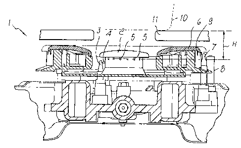
accompanying drawing, wherein the only figure is a transverse sectional view
of the gas-
fired burner according to the present invention.
DESCRIPTION OF THE PREFERRED EMBODIMENTS OF THE INVENTION
i5 With reference to the figure cited above, a gas-fired burner according to
the present
invention, generally designated by the reference numeral 1, comprises a burner
2 with a
corresponding thermocouple 3 and an igniter 4. The burner 2 is provided with a
plurality
of nozzles 5 for emission of the gas to generate the flame.
The figure illustrates a burner configuration with a double ring, in which in
addition to
20 the central burner 2 there is an external burner 6, which is likewise
provided with a
thermocouple 7 and an igniter 8. In this case, the nozzles of the outer burner
are
designated by the reference numeral 9.
According to the invention, the distance between at least one of the burners 2
and 6
and the bottom of a container 10 arranged on the cooking range and
specifically on a
25 grate 11 of the cooking range, which lies above the burner or burners 2 and
6, must be
such as to ensure maximum combustion efficiency together with the ability to
have a
minimum heat emission and a maximum heat emission that are very widely spaced,
i.e.,
the minimum heat emission must be approximately 200 BTU/h and the maximum heat
emission must be approximately 20,000 BTUIh. This is equivalent to a turn-down
ratio of
3o approximately 100.

CA 02486610 2004-11-03
-4-
In particular, if H is the distance between the nozzles 5 of the inner burner
2 and the
lower surface of the container 10 in which the food to be cooked or heated is
arranged, or
as an alternative the upper surface of the grate 11 on which the container 10
is arranged,
it is possible to find a relation that links the distance H to the power of
the burner, i.e., to
s heat emission over time, and inversely links it to the temperature relation
between the
heat source and the container in which the food is placed.
This relation can be expressed for example as
hC - P
~kdT
The parameter k indicates the thermal conductivity of the material to which
heat is
transmitted, i.e., the food, the container, or both.
to The distance H is optimum for meeting the requirements listed above when it
is at
least equal to 10 mm or greater.
In the case of a plurality of burners, as shown in the figure, the inner
burner must be
arranged downward with respect to the outer burner, i.e., the nozzles 5 of the
inner
burner 2 must be at a height, with respect to the bottom of the container 10,
that is lower
15 than the height at which the nozzles 9 of the outer burner 6 are arranged.
In practice it has been found that the burner according to the present
invention fully
achieves the intended aim and objects, since it allows, with the previously
mentioned
distance between the nozzles of the burner and the bottom surface of the
container in
which the food to be cooked is arranged, to obtain an extremely wide heat
emission
2o range, from approximately 200 BTUIh to approximately 20,000 BTUIh.
In the case of a plurality of burners, the inner burner must be arranged at
lower height,
with respect to the bottom surface of the container, than the outer burner.
In this case also, the distance H is the one cited above.
The burner thus conceived is susceptible of numerous modifications and
variations,
25 within the scope of the appended claims. All the details may be replaced
with other
technically equivalent elements. In practice, the materials used, as well as
the shapes
and dimensions, may be any according to requirements and to the state of the
art.

Representative Drawing
A single figure which represents the drawing illustrating the invention.
Administrative Status

2024-08-01:As part of the Next Generation Patents (NGP) transition, the Canadian Patents Database (CPD) now contains a more detailed Event History, which replicates the Event Log of our new back-office solution.

Please note that "Inactive:" events refers to events no longer in use in our new back-office solution.

For a clearer understanding of the status of the application/patent presented on this page, the site Disclaimer , as well as the definitions for Patent , Event History , Maintenance Fee  and Payment History  should be consulted.

Event History

Description Date
Application Not Reinstated by Deadline 2013-06-05
Inactive: Dead - Final fee not paid 2013-06-05
Deemed Abandoned - Failure to Respond to Maintenance Fee Notice 2012-11-05
Deemed Abandoned - Conditions for Grant Determined Not Compliant 2012-06-05
Notice of Allowance is Issued 2011-12-05
Letter Sent 2011-12-05
Notice of Allowance is Issued 2011-12-05
Inactive: Approved for allowance (AFA) 2011-11-03
Letter Sent 2010-12-08
Reinstatement Requirements Deemed Compliant for All Abandonment Reasons 2010-11-26
Deemed Abandoned - Failure to Respond to Maintenance Fee Notice 2010-11-03
Inactive: Correspondence - MF 2010-08-10
Letter Sent 2010-05-19
Inactive: Single transfer 2010-04-21
Letter Sent 2009-12-15
Amendment Received - Voluntary Amendment 2009-11-18
Request for Examination Requirements Determined Compliant 2009-10-30
All Requirements for Examination Determined Compliant 2009-10-30
Request for Examination Received 2009-10-30
Application Published (Open to Public Inspection) 2005-11-03
Inactive: Cover page published 2005-11-02
Letter Sent 2005-09-12
Inactive: Single transfer 2005-07-08
Inactive: First IPC assigned 2005-02-17
Inactive: Courtesy letter - Evidence 2005-01-04
Inactive: Filing certificate - No RFE (English) 2004-12-30
Filing Requirements Determined Compliant 2004-12-30
Application Received - Regular National 2004-12-30

Abandonment History

Abandonment Date Reason Reinstatement Date
2012-11-05
2012-06-05
2010-11-03

Maintenance Fee

The last payment was received on 2011-09-27

Note : If the full payment has not been received on or before the date indicated, a further fee may be required which may be one of the following

  • the reinstatement fee;
  • the late payment fee; or
  • additional fee to reverse deemed expiry.

Please refer to the CIPO Patent Fees web page to see all current fee amounts.

Owners on Record

Note: Records showing the ownership history in alphabetical order.

Current Owners on Record
FULGOR S.R.L.
Past Owners on Record
DAVID WARD
ORIO PURICELLI
Past Owners that do not appear in the "Owners on Record" listing will appear in other documentation within the application.
Documents

To view selected files, please enter reCAPTCHA code :


To view images, click a link in the Document Description column. To download the documents, select one or more checkboxes in the first column and then click the "Download Selected in PDF format (Zip Archive)" or the "Download Selected as Single PDF" button.

List of published and non-published patent-specific documents on the CPD .

If you have any difficulty accessing content, you can call the Client Service Centre at 1-866-997-1936 or send them an e-mail at CIPO Client Service Centre.


Document
Description 
Date
(yyyy-mm-dd) 
Number of pages   Size of Image (KB) 
Description 2004-11-03 4 185
Abstract 2004-11-03 1 12
Drawings 2004-11-03 1 28
Claims 2004-11-03 1 19
Representative drawing 2005-10-11 1 19
Cover Page 2005-10-20 1 44
Filing Certificate (English) 2004-12-30 1 158
Courtesy - Certificate of registration (related document(s)) 2005-09-12 1 104
Reminder of maintenance fee due 2006-07-05 1 110
Reminder - Request for Examination 2009-07-06 1 116
Acknowledgement of Request for Examination 2009-12-15 1 175
Courtesy - Certificate of registration (related document(s)) 2010-05-19 1 125
Courtesy - Abandonment Letter (Maintenance Fee) 2010-12-08 1 172
Notice of Reinstatement 2010-12-08 1 163
Commissioner's Notice - Application Found Allowable 2011-12-05 1 163
Courtesy - Abandonment Letter (NOA) 2012-08-28 1 164
Courtesy - Abandonment Letter (Maintenance Fee) 2012-12-31 1 171
Correspondence 2004-12-30 1 26
Fees 2006-11-01 1 41
Fees 2007-10-30 1 43
Fees 2008-11-03 1 54
Fees 2009-11-02 1 53
Correspondence 2010-08-10 1 47
Correspondence 2010-12-08 1 99
Correspondence 2010-12-08 1 77
Fees 2010-11-26 1 50
Fees 2011-09-27 1 51
Correspondence 2011-12-05 1 81