Note: Descriptions are shown in the official language in which they were submitted.
CA 02487140 2011-03-24
52132-63
MAGNETIC RESONANCE PROBES
BACKGROUND
[0001] Leads (catheters) for a wide variety of medical procedures, such as
Deep Brain
Stimulation (DBS) and cardiac interventions, are typically placed into the
body of a
subject under stereotactic guidance, fluoroscopy, or other methods.
Stereotactic
guidance is a static method based on high resolution images taken prior to the
procedure and does not take into account displacement of the brain caused by
the loss
of cerebral spinal fluid (CSF), blood or simple brain tissue displacement by
the
surgical tool. It is therefore often necessary to perform a real time
physiological
localization of the target area to augment and verify the previously obtained
stereotactic data by observing the patients response to stimulation through
the OBS
electrodes or by recording and displaying (visual or audible) the action
potentials of
individual neurons along the path way to the target zone using
microelectrodes.
These additional steps are time consuming; resulting in procedures between 6-8
hours
with a failure rate still remaining between 20-30%.
[0002] Cardiac procedures are mainly performed using X-ray fluoroscopy.
Because
X-ray shadows are the superposition of contributions from many structures, and
since
the discrimination of different soft tissues is not great, it is often very
difficult to
determine exactly where the catheter is within the heart. In addition, the
borders of
the heart are generally not accurately defined, so it is generally not
possible to know
whether the catheter has penetrated the wall of the heart. Furthermore,
lesions are
invisible under x-ray fluoroscopy. Thus, it is very difficult to discern
whether tissue
has been adequately ablated.
[0002A] Parkinson's disease is a progressive neurological disorder in
regions of the midbrain containing a cluster of neurons known as the
"substantia nigra". These neurons produce the chemical dopamine, a
neurotransmitter (messenger) responsible for transmitting signals between the
substantia nigra and several clusters of neurons that comprise the basal
ganglia and is
vital for normal movement. When dopamine levels drop below 80%, symptoms of
Parkinson's disease begin to emerge causing nerve cells of the basal ganglia
to fire out
of control; resulting in tremor, muscle stiffness or rigidity, slowness of
movement
(bradykinesia) and loss of balance. Although medication masks some symptoms
for a
-1-
CA 02487140 2011-03-24
52132-63
limited period, generally four to eight years in most patients, they begin
causing dose-
limiting side effects. Eventually the medications lose their effectiveness,
leaving the
patient unable to move, speak or swallow. Several preventive and restorative
strategies such as neural cell transplantation, neural growth factors, gene
therapy
techniques and surgical therapies (including DBS), have shown promise in
animal
studies and human clinical trials. Important links to the cause (including
genetic
susceptibility and the role of toxic agents) are becoming established. Leading
scientists describe Parkinson's as the neurological disorder most likely to
produce a
breakthrough therapy and/or cure within this decade. Parkinson's disease
afflicts
approximately 1 million Americans, nearly 40 percent of whom are under the age
of
60. Roughly 60,000 cases of PD are diagnosed each year. It is estimated that
Parkinson's disease costs society $25 billion or more annually.
[0002B] Essential tremor (ET) is considered the most common neurological
movement
disorder affecting nearly 10 million people in the United States. ET is a
chronic
condition characterized by involuntary, rhythmic tremor of a body part, most
typically
the hands and arms, often the head and voice, but rarely the legs. ET is
generally
considered a slowly progressive disorder, although many individuals may have a
mild
form of ET throughout life that never requires treatment. The most common form
of
ET affects the arms and hands, usually bilaterally, and is most prominent with
the
arms held against gravity (postural tremor) or in action (kinetic tremor) such
as when
writing or drinking from a cup. Unlike patients with Parkinson's disease,
patients with
ET rarely exhibit a tremor when the arm is at rest. Pharmacological treatment
for ET
includes a class of drugs called Beta-adrenergic blocking agents (such as
propranolol),
benefiting about 50 to 60 percent of patients. Primidone (MYSOLINE) is
commonly
regarded as the most effective drug. Side effects of these drugs include:
bradycardia
(slow heart rate), hypotension (low blood pressure), dizziness, fatigue,
depression,
diarrhea, nausea and/or sexual dysfunction. Surgical treatment of ET has for
years
involved placing a lesion in certain cluster of cells called the thalamus.
This
procedure, called stereotaxic thalamotomy has been quite effective in
substantially
reducing tremor intensity, although there is a finite risk of stroke or other
surgical
complications and bilateral thalamotomies increase the risk of speech
impairment
(dysarthria). The recent development of high frequency stimulation of the
thalamus
(deep brain. stimulation) has provided a safer and more effective surgical
strategy for
-2-
CA 02487140 2011-03-24
52132-63
treating ET. This procedure involves the placement of an electrode in a region
of the
thalamus (Ventral Intermediate Nucleus or VIM).
[0002C] Multiple sclerosis (MS) tends to begin in young adulthood and affects
about
500,000 people in the United States. Worldwide, the incidence rate is
approximately
0.01 % with Northern Europe and the northern US having the highest prevalence
with
more than 30 cases per 100,000 people. MS is a chronic, progressive,
degenerative
disorder that affects nerve fibers in the brain and spinal cord. A fatty
substance (called
myelin) surrounds and insulates nerve fibers and facilitates the conduction of
nerve
impulse transmissions. MS is characterized by intermittent damage to myelin
(called
demyelination) caused by the destruction of specialized cells
(oligodendrocytes) that
form the substance. Demyelination causes scarring and hardening (sclerosis,
plague)
of nerve fibers usually in the spinal cord, brain stem, and optic nerves,
which slows
nerve impulses and results in weakness, numbness, pain, and vision loss. MS
can
affect any part of the central nervous system. When it affects the cerebellum
or the
cerebellum's connections to other parts of the brain, severe tremor can
result. Since
the sub cortical gray matter also contains myelinated nerve fibers, plaques
can also be
found in the striatum, pallidum and thalamus. This may be the pathological
basis for
the other movement disorders seen in a small proportion of patients with MS.
Because
different nerves are affected at different times, MS symptoms often exacerbate
(worsen), improve, and develop in different areas of the body. Early symptoms
of the
disorder may include vision changes (e.g., blurred vision, blind spots) and
muscle
weakness. MS can progress steadily or cause acute attacks (exacerbations)
followed
by partial or complete reduction in symptoms (remission). Most patients with
the
disease have a normal lifespan.
[0002D] In a typical DBS procedure, a stereotactic frame, e.g. an Ieksell
frame, is
attached (bolted) to the patient prior to any portion of the surgical
intervention. This
is often done in a separate small operating room, either under sedation
(Midazolam,
Fentanyl, Propofol) and/or local anesthesia (Lidocaine). After the frame is
attached,
the patient is transferred to the table of the imaging system (CT or MR) and
the
patient's head is immobilized. A box containing fiduciary markers is fitted on
to the
frame. These markers will show up in subsequent images in precisely known
locations, allowing an accurate mapping between the frame coordinates and
brain
-3-
CA 02487140 2011-03-24
52132-63
structures. Based on these detailed images and coordinate mappings, the
trajectory for
the surgery using a planning software program.
[0002E] Typical targets for the procedure include regions in the Thalamus, the
Globus
Pallidum Internus (Gpi) and the Subthalamic Nucleus (SNT). The target
selection
strongly depends on the disease and symptoms treated. DBS in the GPi seems to
be
very effective for drug-induced dyskinesia and helps control tremor and
bradykinesia.
DBS in the SNT seem to be most effective as measured by ability of patients to
reduce their medications, however, there is a potential for increasing
dyskinesia. The
Thalamus is not necessarily a good target for patients with Parkinson's
disease but has
been found to improve conditions for patients with Essential Tremor and
movement
disorder caused by Multiple Sclerosis.
[0002F] Once the target has been effectively localized and noted to be in a
safe
location, effort must be placed on a safe entry and trajectory to the target.
MRI
surface images of the cerebral cortex in combination with the DBS planning
scans can
be useful to avoid injuries to cerebral arteries or veins at the initial drill
holes and due
to passage of the DBS electrode, resulting in a catastrophic hemorrhage. With
the
stereotactic software system, trajectory slices are possible so that every
stage of the
trajectory can be visualized in terms of its potential harm as an electrode is
passed
toward the target. Fine adjustments to the entry point can be made to avoid
these
critical structures or avoid passage through the ventricular system in the
patient with
large ventricles.
[0002G] Entry point coordinates are not directly utilized during operative
planning but
are used by the computer system in creating the trajectory itself. An estimate
of
accuracy can then be obtained and is usually accurate within several hundred
microns
and always less than 0.5 cm accuracy so that the results from imaging and
planning
can be used effectively during the surgical procedure.
[0002H] Once the planning process is completed, the patient is transferred to
the
operating room and a hole is drilled into the patient's skull (0.5" to 1.0").
At this
point, most surgery centers will perform a real time physiological
localization of the
target area to augment and verify the previously obtained stereotactic data by
observing the patients response to stimulation through the DBS electrodes or
by
recording and displaying (visual or audible) the action potentials of
individual
-4-
CA 02487140 2011-03-24
52132-63
neurons along the path way to the target zone using microelectrodes. The
additional
step is considered necessary because the shape of the brain and the position
of
anatomical structures can change during neuro-surgical procedures. Such
changes
can be due to differences between the patient's position in acquisition and
during
surgery, reduction in volume due to tissue resection or cyst drainage, tissue
displacement by the instruments used, changes in blood and extra cellular
fluid
volumes, or loss of cerebrospinal fluid when the skull is opened. The amount
of brain
shift can in a severe case be a centimeter or more and is in most cases
between I and
2 mm.
1000211 In addition to the brain shift phenomenon, some subsection of specific
nuclei
cannot yet be identified by anatomic means, again requiring a physiological
determination of the target area. Given these "uncertainties," several target
runs may
be required before the desired results are achieved. Throughout the procedure,
responses from the patient are necessary to determine if the target area has
been
reached and if there are any unwanted site effects. Once the target area has
been
correctly identified, the microelectrode is removed and replaced with the DBS
electrode. Stimulation voltage levels are determined by observing the patient
and the
physiological response. Once all parameters have been correctly adjusted, the
DBS
electrode is anchored in the skull, a pacemaker is implanted subcutaneously in
the
subclavicular region and the lead is tunneled under the scalp up the back of
the neck
to the top of the head.
[0002J] One of the major shortcomings with stereotactic DBS is the requirement
of
sub millimeter accuracy in electrode placement for the electrical stimulation
of target
areas deep inside the brain. As pointed out, brain shifts of I to 2 mm can
routinely
occur between the acquisition of images for the stereotactic surgery and the
surgery
itself and is either caused by patient transport (misregistration, image
distortion), loss
of fluid (blood, CSF) or simple tissue displacement by the instruments used. A
long
recognized solution to these issues has been to perform real time MRI guided
surgery.
To this end a variety of MRI systems have been developed. "Open MRI" systems
which are typically operated at field strength ranging from 0.12.T (Odin) to
1.0 T
(Philips) offer a clear advantage in patient access over the closed bore
systems
ranging in field strength from 1.0 T to 3.0 T. However, these high field short
bore
-5-
CA 02487140 2011-03-24
52132-63
systems outperform the low field systems in Signal-to-Noise Ratio since the
SNR
depends linearly on field strength. Higher SNR translates directly into
resolution
and/or imaging speed. Efforts have.been undertaken to increase the field
strength of
these open systems (Philips 1.0T), however, it is not clear that much higher
magnetic
fields are desirable or achievable due to considerable mechanical challenges
of
stabilizing the separated pole faces of these magnets and the fact that these
magnets
are not easily shielded and have a larger fringe field than comparable "closed
bore"
systems. Furthermore, significant progress has been made to increase the
patient
access in high field systems as well. Traditionally, whole body 3 T MRI
systems
have had a length in access of 2m. Over the past few years dedicated head
scanners
(Allegra, Siemens) have been developed and have reduced the system length to
1.25
m, allowing relatively easy access to the patient's head. Similar progress has
been
made in whole body scanners at 1.5 T. Since the actual magnet is significantly
shorter (68 to 80 cm) than the overall system further improvements in patient
access
can be expected. Image quality, speed and patient access are now at a point
where
true interventional MRI is feasible. All major OEM's have recognized the need
for a
fully integrated MRI operating room and have made significant progress towards
this
goal. Siemens has introduced the "BrainSuite", a fully integrated MRI suite
for
neuro-surgery. Philips, Siemens and GE have also introduced XMRI systems,
combining 1.5 T or 3 T whole body systems with an X-Ray fluoroscopy with a
patient
table/carrier linking both systems.
[0002K] Atrial fibrillation and ventricular tachyarrhythmias occurring in
patients with
structurally abnormal hearts are of great concern in contemporary cardiology.
They
represent the most frequently encountered tachycardias, account for the most
morbidity and mortality, and, despite much progress, remain therapeutic
challenges.
[0002L] Atrial fibrillation affects a larger population than ventricular
tachyarrhythmias,
with a prevalence of approximately 0.5% in patients 50-59 years old,
increasing to
8.8% in patients in their 80's. Framingham data indicate that the age-adjusted
prevalence has increased substantially over the last 30 years, with over 2
million
people in the United States affected. Atrial fibrillation usually accompanies
disorders
such as coronary heart disease, cardiomyopathies, and the postoperative state,
but
occurs in the absence of any recognized abnormality in 10% of cases. Although
it
may not carry the inherent lethality of a ventricular tachyarrhythmia, it does
have a
-6-
CA 02487140 2011-03-24
52132-63
mortality twice that of control subjects. Symptoms which occur during atrial
fibrillation result from the often rapid irregular heart rate and the loss of
atrio-
ventricular (AV) synchrony. These symptoms, side effects of drugs, and most
importantly, thrombo-embolic complications in the brain (leading to
approximately
75,000 strokes per year), make atrial fibrillation a formidable challenge.
10002M] Two strategies have been used for medically managing patients with
atrial
fibrillations. The first involves rate control and anticoagulation, and the
second
involves attempts to restore and maintain sinus rhythm. The optimal approach
is
uncertain. In the majority of patients, attempts are made to restore sinus
rhythm with
electrical or pharmacologic cardioversion. Current data suggest
anticoagulation is
needed for 3 to 4 weeks prior to and 2 to 4 weeks following cardioversion to
prevent
embolization associated with the cardioversion. Chronic antiarrhythmic therapy
may
be indicated once sinus rhythm is restored. Overall, pharmacologic, therapy is
successful in maintaining sinus rhythm in 30 to 50% of patients over one to
two years
of follow-up. A major disadvantage of antiarrhythmic therapy is the induction
of
sustained, and sometimes lethal, arrhythmias (proarrhythmia) in up to 10% of
patients.
[0002N] If sinus rhythm cannot be maintained, several approaches are used to
control
the ventricular response to atrial fibrillation. Pharmacologic agents which
slow
conduction through the AV node are first tried. When pharmacologic approaches
to
rate control fail, or result in significant side effects, ablation of the AV
node, and
placement of a permanent pacemaker may be considered. The substantial
incidence of
thromboembolic strokes makes chronic anticoagulation important, but bleeding
complications are not unusual, and anticoagulation cannot be used in all
patients.
[00020] In addition to medical management approaches, surgical therapy of
atrial
fibrillation has also been performed. The surgical-maze procedure, developed
by Cox,
is an approach for suppressing atrial fibrillation while maintaining atrial
functions.
This procedure involves creating multiple linear incisions in the left and
night atria.
These surgical incisions create lines that block conduction and
compartmentalize the
atrium into distinct segments that remain in communication with the sinus
node. By
reducing the mass of atrial tissue in each segment, the mass of atrial tissue
is
insufficient to sustain the multiple reentrant rotors, which are the basis for
atrial
-7-
CA 02487140 2011-03-24
52132-63
fibrillation. Surgical approaches to the treatment of atrial fibrillation
result in an
efficacy of >95% and a low incidence of complications. However, despite these
encouraging results, this procedure has not gained widespread acceptance
because of
the long duration of recovery and risks associated with cardiac surgery.
[0002P] Invasive studies of the electrical activities of the heart
(electrophysiologic
studies) have also been used in the diagnosis and therapy of arrhythmias.
Focal atrial
tachycardias, AV-nodal reentrant tachycardias, accessory pathways, atrial
flutter, and
idiopathic ventricular tachycardia can be cured by selective destruction of
critical
electrical pathways with radiofrequency (RF) catheter ablation.
Electrophysiologists
have attempted to replicate the maze procedure using RF catheter ablation. The
procedure is arduous, requiring general anesthesia and procedure durations
often
greater than 12 hours, with exposure to ionizing x-ray irradiation for over 2
hours.
Some patients have sustained cerebrovascular accidents. One of the main
limitations
of the procedure is the difficulty associated with creating and confirming the
presence
of continuous linear lesions in the atrium. If the linear lesions have gaps,
then
activation can pass through the gap and complete a reentrant circuit, thereby
sustaining atrial fibrillation or flutter. This difficulty contributes
significantly to the
long procedure durations discussed above.
[0002Q] Creating and confirming continuous linear lesions and morbidity could
be
facilitated by improved minimally-invasive techniques for imaging lesions
created in
the atria. Such an imaging technique may allow the procedure to be based
purely on
anatomic findings.
[0002R1 The major technology for guiding placement of a catheter is x-ray
fluoroscopy. For electrophysiologic studies and ablation, frame rates of 7-15
per
second are generally used which allows an operator to see x-ray-derived
shadows of
the catheters inside the body. Since x-rays traverse the body from one side to
the
other, all of the structures that are traversed by the x-ray beam contribute
to the
image. The image, therefore is a superposition of shadows from the entire
thickness of
the body. Using one projection, therefore, it is only possible to know the
position of
the catheter perpendicular to the direction of the beam. In order to gain
information
about the position of the catheter parallel to the beam, it is necessary to
use a second
beam that is offset at some angle from the original beam, or to move the
original
-8-
CA 02487140 2011-03-24
52132-63
beam to another angular position. The intracardiac electrogram may be used to
guide
the catheters to the proper cardiac tissue.
[0002S] Intracardiac ultrasound has been used to overcome deficiencies in
identifying
soft tissue structures. With ultrasound it is possible to determine exactly
where the
walls of the heart are with respect to a catheter and the ultrasound probe,
but the
ultrasound probe is mobile, so there can be doubt where the absolute position
of the
probe is with respect to the heart.
[0002T] Neither x-ray fluoroscopy nor intracardiac ultrasound have the ability
to
accurately and reproducibly identify areas of the heart that have been
ablated.
[0002U] A system known as "non-fluoroscopic electro-anatomic mapping" (U.S.
Pat.
No. 5,391,199 to Ben-Haim), was developed to allow more accurate positioning
of
catheters within the heart. That system uses weak magnetic fields and a
calibrated
magnetic field detector to track the location of a catheter in 3D-space. The
system can
mark the position of a catheter, but the system relies on having the heart not
moving
with respect to a marker on the body. The system does not obviate the need for
initial
placement using x-ray fluoroscopy, and cannot directly image ablated tissue.
SUMMARY
[00031 The systems and methods disclosed herein may simplify the manufacturing
process for magnetic resonance probes, increase patient safety, reduce if not
eliminate
tissue heating, and facilitate the performance of multiple functions during
MRI
interventional procedures such as Deep Brain Stimulation, Electrophysiological
Mapping, and/or RF Ablation.
[0004] In an embodiment, a magnetic resonance probe may include a plurality of
center conductors, at least some center conductors including a conductive core
and an
insulator disposed at least partially about the core along at least a portion
of the core.
A first dielectric layer may be disposed at least partially about the
plurality of center
conductors in a proximal portion of the probe. An outer conductive layer may
be at
least partially disposed about the first dielectric layer. A plurality of
electrodes may
be included, at least one electrode being coupled to one of the center
conductors and
disposed at least partly on a probe surface.
CA 02487140 2011-03-24
52132-63
[0005] In an embodiment, a probe may include a second dielectric layer at
least
partially disposed about the outer conductor. In an embodiment, the plurality
of center
conductors may be magnetic resonance-compatible. In an embodiment, at least
one
insulator may have a thickness up to about 100 microns. In an embodiment, at
least
some center conductors may form a first pole of a dipole antenna, and the
outer
conductive layer may form a second pole of the dipole antenna. In an
embodiment, a
probe can include a plurality of radially expandable arms. In an embodiment,
at least
one electrode may be at least partly disposed on an arm.
[0006] In an embodiment, an interface circuit may be electrically coupled to
the
probe, the interface circuit including a signal splitter that directs a signal
received
from the probe to a magnetic resonance pathway and an electrophysiology
pathway,
a high-pass filter disposed in the magnetic resonance pathway, a low-pass
filter
disposed in the electrophysiology pathway, a connector disposed in the
magnetic
resonance pathway for connecting to a magnetic resonance scanner, and a
connector disposed in the electrophysiology pathway for connecting to at least
one of
a tissue stimulator, a biopotential recording system, and an ablation energy
source.
[0006A] In another embodiment, there is provided a combined magnetic
resonance imaging and electrophysiology probe, comprising: a plurality of
center
conductors, at least some center conductors including a conductive core and an
insulator disposed at least partially about the core along at least a portion
of the core,
the insulator having a thickness equal to or less than about 100 microns; a
first
dielectric layer disposed at least partially about the plurality of center
conductors in a
proximal portion of the probe; an outer conductive layer at least partially
disposed
about the first dielectric layer; a second dielectric layer disposed at least
partially about
the outer conductive layer; and a plurality of electrodes, at least one
electrode coupled
to one of the center conductors and disposed at least partly on the probe
surface.
[0006B] In another embodiment, there is provided a system for magnetic
resonance imaging, comprising: a magnetic resonance probe, including: a
plurality of
center conductors, at least some center conductors including a conductive core
and
-10-
CA 02487140 2011-03-24
52132-63
an insulator disposed at least partially about the core along at least a
portion of the
core; a first dielectric layer disposed at least partially about the plurality
of center
conductors in a proximal portion of the probe; an outer conductive layer
disposed at
least partially about the first dielectric layer; and a plurality of
electrodes, at least one
electrode coupled to one of the center conductors and disposed at least partly
on the
probe surface; and a interface electrically coupled to the probe, the
interface
including: a signal splitter that directs a signal received from the probe to
a magnetic
resonance pathway and an electrophysiology pathway; a high-pass filter
disposed in
the magnetic resonance pathway; a low-pass filter disposed in the
electrophysiology
pathway; a connector disposed in the magnetic resonance pathway for connecting
to
a magnetic resonance scanner; and a connector disposed in the
electrophysiology
pathway for connecting to at least one of a tissue stimulator, a
electrophysiological
recording system, and an ablation energy source.
BRIEF DESCRIPTION OF THE DRAWINGS
[0007] Embodiments of the disclosed systems and methods will be apparent
from the following more particular description of exemplary embodiments as
illustrated in the accompanying drawings, in which some reference characters
refer to
the same parts throughout the various views. The drawings are not necessarily
to
scale, nor are individual elements necessarily in relative proportion to other
elements,
emphasis instead being placed upon illustrating principles of the disclosed
systems
and methods.
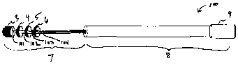
[0008] FIG. I depicts an exemplary embodiment of a magnetic resonance
probe having four center conductors and four electrodes.
[0009] FIGS. 2A-C depict an exemplary embodiment of a magnetic resonance
probe having four center conductors and four electrodes. FIG. 2A depicts a
side
view. FIG. 2B depicts a cross section in a distal portion of the probe. FIG.
2C
depicts a cross section in a proximal portion of the probe.
-11-
CA 02487140 2011-03-24
52132-63
[0010] FIGS. 3A-E depict exemplary embodiments of an interface circuit. FIGS.
3A
and 3B depict exemplary electrical schematics; FIGS. 3C-3E depict exemplary
physical layouts.
[0011] FIGS. 4A-4C depict an exemplary embodiment of a steerable magnetic
resonance probe.
[0012] FIGS. 5A-5C depict an exemplary embodiment of a magnetic resonance
probe having cooling lumens.
[0013] FIGS. 6A-6D depicts an exemplary embodiment of a magnetic resonance
.probe having expandable arms. FIG. 6A depicts a side view of the exemplary
probe.
FIG. 6B depicts a long axis view of an arm. FIG. 6C depicts a cross section of
expanded arms. FIG. 6D depicts a cross section in a proximal portion of the
exemplary probe.
[0014] FIGS. 7A-B show heating profiles of tissue surrounding an exemplary
magnetic resonance probe in the transmit mode that is decoupled (FIG. 7A) or
not
decoupled (FIG. 7B).
.10115]...FIGS....8A-C .dep].ct_an_exempW.y.-embadiment of.a_bidirectionally_
steerable.... .
magnetic resonance probe having wires that are both pull wires and center
conductors.
[0016] FIGS. 9A-C depict an exemplary embodiment of a unidirectionally
steerable
magnetic resonance probe having an offset wire that is both a pull wire and
center
conductor.
[0017] FIGS. IOA-C depict an exemplary embodiment of a unidirectionally
steerable
magnetic resonance probe having a centered wire that is both a pull wire and
center
conductor.
-12-
CA 02487140 2011-03-24
52132-63
DETAILED DESCRIPTION
[00181 The disclosed systems and methods relate to the guidance and
visualization of
diagnostic and therapeutic procedures performed under Magnetic Resonance
Imaging
(MRI). Such procedures in general benefit from the excellent soft tissue
contrast
obtainable with MRI. Examples of such applications are Deep Brain Stimulation
(DBS) for the treatment of movement disorders (Parkinson's disease, Essential
tremor, etc.) and other neurological disorders benefiting from electrical
stimulations
of section of the brain, as well as the diagnosis and treatment of cardiac
arrhythmias
including but not limited to atrial fibrillation and ventricular tachycardia.
[0019] Real time Magnetic Resonance Imaging can overcome both the inaccuracies
of stereotactic planning and the lack of soft tissue contrast as found in X-
ray
fluoroscopy. The use of Magnetic Resonance Imaging guided interventions can
therefore result in shortened procedure times and increased success rates.
(0020] Some conditions that may benefit from MRI-guided DBS include
Parkinson's
disease, essential tremor, and multiple sclerosis.
[00411 Embodiments of fixed, steerable, cooled and Multi Electrode Array
probes are
described that may incorporate multiple functions, such as the recording of
MRI
imaging signals, bio potentials (electrophysiological, neurological) and
cooling. The
probes can significantly reduce heating-induced injury in materials
surrounding them
and can be easily visualized under MRI or X-ray. Disclosed embodiments are
illustrative and not meant to be limiting. Drawings illustrate exemplary
embodiments
and design principles; absolute or relative dimensions are not to be inferred
therefrom
as necessarily pertaining to a particular embodiment.
[00421 FIG.1 shows schematically an exemplary embodiment of a magnetic
resonance probe 100. The probe 100 may have a distal portion 7 and a proximal
portion 8. The distal portion may include a plurality of electrodes, such as
electrodes
3, 4, 5, 6. As shown, the electrodes may be disposed at least partly on a
surface of the
probe 100. An electrode can be disposed so that the electrode is disposed on
the
- 12a -
CA 02487140 2011-03-24
52132-63
surface around the circumference of the probe 100 (as shown for electrodes 4,
5, and
6), disposed at the tip of the probe 100 (as shown for electrode 3), or so
that the
electrode is disposed at the surface around one or more portions of the
circumference.
The probe 100 shown in FIG.1 has four electrodes, but other numbers of
electrodes
5. may be provided, such as few as one electrode. Probe 100 may include a
plurality of
center conductors, such as center conductors 101, 102, 103, 104. Other numbers
of
center conductors may be provided. As shown in this exemplary embodiment,
center
conductors 101, 102, 103, 104 may be coupled to corresponding electrodes 3, 4,
5; 6.
The center conductors may extend through the probe 100 and terminate in a
connector
9 at the proximal end of the probe 100. One or more additional layers,
described in
greater detail below, may be disposed at least partially about the center
conductors in
the proximal portion 8 of the probe 100.
(0043] FIGS. 2A-C depict additional features of an exemplary embodiment of a
probe 100. As shown in FIG. 2A, a junction J may define the transition between
the
distal portion 7 and the proximal portion 8 of the probe 100. The position of
the
junction J may be selected to provide the probe 100 with preferred electrical
properties, discussed in greater detail below. In an embodiment, the junction
J may
be positioned so that the distal portion 7 of the probe 100 has a length
approximately
- 12b -
CA 02487140 2004-11-24
WO 03/102614 PCT/US03/17085
equal to one quarter the wavelength of an MR signal in the surrounding medium.
For
a medium such as blood or tissue, the preferred length for the distal portion
7 can be
in the range of about 3 cm to about 15 cm. The center conductors 2 (referenced
collectively) may be coiled to reduce the physical length of the distal
portion 7 while
maintaining the "quarter wave" electrical length. As shown in cross section
FIG. 2B,
the distal portion 7 of probe 100 may include a plurality of center conductors
2 and a
lubricious coating 1 disposed the plurality of center conductors. Exemplary
lubricious
coatings include polyvinylpyrrolidone, polyacrylic acid, hydrophilic
substance,
silicone, and combinations of these, among others.
[0044] With continued reference to FIGS. 2A and 2C, the proximal portion 8 of
the
probe 100 may include one or more additional layers disposed at least
partially about
the plurality of center conductors 2. For example, a first dielectric layer 31
may be
disposed at least partially about the plurality of center conductors 2. The
first
dielectric layer 31 may define a lumen 13 in which the plurality of center
conductors
2 may be disposed. An outer conductive layer 12 may be at least partially
disposed
about the first dielectric layer. The outer conductive layer 12 may include a
braiding.
The outer conductive layer 12 may extend through the probe 100 and terminate
at the
connector 9. A second dielectric layer 10 may be at least partially disposed
about the
outer conductive layer 12. A lubricious coating 1 may be at least partially
disposed
about the outer conductive layer 12 and/or the second dielectric layer 10 in
the
proximal portion 8 of the probe 100.
[0045] As described above, a plurality of center conductors may be provided. A
center conductor may include a conductive core. A center conductor may include
an
insulator disposed at least partially about the core along at least a portion
of the core.
The insulator may be disposed about the core to prevent contact between
various
cores. The insulator may be disposed along the entire length of the core or
along one
or portions thereof. In an embodiment, an insulator may be disposed about
substantially the entire length of a core except for a distal portion for
coupling to an
electrode. Insulator may be selectively disposed about core, such as
discontinuously
or on only a selected aspect of a core, such as an aspect that faces another
core. Thus,
insulator may be disposed about one or more cores so that one or more center
conductors may be touching but cores are not in contact.
-13-
CA 02487140 2004-11-24
WO 03/102614 PCT/US03/17085
[0046] The insulator can facilitate positioning a center conductors in close
proximity
to another center conductor. For example, two center conductors may touch but
not
have the respective cores be in contact. Such close arrangement of center
conductors
can permit electrical coupling between the center conductors of high-frequency
energy, such as magnetic resonance energy, while preventing coupling of low-
frequency energy between the center conductors. Coupling the center conductors
for
high-frequency energy facilitates receiving magnetic resonance signals with
the center
conductors because the center conductors so coupled can act as a single
electrical
entity with respect to the high-frequency energy. Thus, the electrical length
of the
distal portion 7 of the probe 100 can be preserved, because magnetic resonance
energy can be conducted straight through the plurality of center conductors,
without
allowing the magnetic resonance energy to pass separately through various
conductors, thereby creating interference, or causing the high-frequency
energy to
move through a longer path, thereby unbalancing a magnetic resonance antenna.
In
contrast, a thin insulating layer can be sufficient to prevent coupling
between
conductors of the low-frequency signals that may be conducted along selected
center
conductors. For example, low-frequency coupling may not be desirable when the
probe 100 is being operated to measure an electrical potential between two
electrodes
contacting various tissue regions. If the center conductors were permitted to
couple
this low-frequency energy, then the potential measurement could be distorted,
lost in
excessive noise, or attenuated entirely. Similarly, ablation energy delivered
along the
probe 100 could be shorted between center conductors if the center conductors
were
permitted to couple low frequency energy.
[0047] Thus, the wire insulation is preferably sufficiently thin so that the
center
conductors are electrically coupled through the insulator at high frequency
(e.g.,
above 10 MHz) but are isolated at frequencies below 0.5 MHz.
[0048] Accordingly, insulator properties may be selected to facilitate
coupling of
high-frequency energy between center conductors, while lessening or inhibiting
coupling of low-frequency energy. Properties include the material or materials
from
which the insulator is made, the thickness of the insulator, the number of
layers of
insulator, the strength of the magnetic field in which the probe 100 may be
immersed,
among others.
-14-
CA 02487140 2004-11-24
WO 03/102614 PCT/US03/17085
[00491 Because the insulator can prevent coupling of low-frequency energy
between
the center conductors, the center conductors can be brought into very close
proximity
to one another, also termed "tightly coupled" to one another. The center
conductors
may be tightly coupled, for example, by twisted around one another. Twisting
or
otherwise tight-coupling the center conductors facilitates keeping the center
conductors in close proximity in the distal portion 7 of the probe 100, where
there
may be no, e.g., first dielectric layer to keep the center conductors closely
apposed. In
addition, because reactive elements need not be interposed between the center
conductors to decouple low-frequency energy, manufacture of the probe is
simplified.
Furthermore, the absence of reactive elements can permit the achievement of
small
probe diameters. For example, a probe having an outer of diameter of about 15
French or less, suitable for, among other uses, cardiac catheterization,
observation,
and/or ablation, can be readily constructed using systems and methods
disclosed
herein. Moreover, deep brain stimulation with a magnetic resonance probe is
facilitated, because the diameter can be reduced to, for example, 4 French or
less, 3
French or less, 2 French or less, 1.3 French or less, I French or less, 0.5
French or
less, or even 0.1 French or less. The outer diameter can be affected by the
thickness
of the center conductor core, thickness of insulator, and thicknesses of other
layers
that may be included. In an embodiment, wire may be used having a thickness of
56
AWG to 16 AWG as well as thinner and/or thicker wire.
[00501 A preferred insulator thickness may be determined as follows. The
inductance
L and capacitance C between a twisted pair of wires per unit length is given
by the
equations:
- 15 -
CA 02487140 2004-11-24
WO 03/102614 PCT/US03/17085
L = (110) cosh-1 (Idl)
C=C1+C2-C3
b
Cl Eo dx
=
D +(1.UIer- 1.0)'D2-x2_4d2-x2
a
C2 7[ EO cosh-1ral
b
_ EO dz
~3- ~ D - sJd2 _.. X2
a
where so = 8.854 pF/m, d is the bare wire diameter in meters, D is the
insulated wire
diameter in meters, and sr is the relative dielectric constant of the
insulating material.
In one illustrative embodiment, a 33 AWG magnet wire was used, the wire having
a
nominal bare wire diameter of 0.0071" (0.00018034 m) and an insulated diameter
of
0.0078" (0.00019812 m) and an approximate dielectric constant of sr = 2. Thus,
the
insulator thickness was about 17.78 microns, or about 8.89 microns on a side.
In this
exemplary case the estimated capacitance per unit length is 89 pF / m. This
corresponds to a capacitive impedance Z, = 1/(2*n*f) of about 28 Q/m at 63.86
MHz
and giving a good coupling at the high frequency range. Because the impedance
scales inversely with frequency, the low frequency impedance at 100 kHz is
estimated
to be 14 kf2/m. An impedance of 10 kS2/m or greater is sufficient in most
applications
to provide sufficient decoupling. The high frequency impedance is preferably
kept
below 100 S2/m.
[0051] The impedance can also be controlled by the choice of dielectric
material.
Typical materials include polyurethane resins, polyvinyl acetal resins,
polyurethane
resins with a polyimide (nylon) overcoat, THEIC modified polyester, THEIC
modified polyester with a polyamideimide (AI) overcoat, THEIC modified
polyester,
oxide-based shield coat and a polyamideimide (AI) overcoat, aromatic polyimide
resin, bondable thermoplastic phenoxy overcoat, glass fiber, All Wood
Insulating
-16-
CA 02487140 2004-11-24
WO 03/102614 PCT/US03/17085
Crepe Paper, Thermally Upgraded Electrical Grade Crepe Kraft Paper, High
Temperature Aramid Insulating Paper, and combinations of these. The length of
the
proximal portion can be modified by selecting dielectric materials for the
first
dielectric layer and/or second dielectric layers. For example, a material with
a high
dielectric constant can be incorporated in one or more dielectric layers,
thereby
decreasing the electrical length of the proximal portion and facilitating use
of a probe
in a relatively shallow anatomic location. Examples of materials with
appropriate
dielectric constants include ceramics.
[0052] An insulator disposed at least partially about a center conductor core
may have
a thickness in a range up to about 2,000 microns, preferably up to about 500
microns,
more preferably up to about 200 microns, still more preferably up to about 100
microns, yet more preferably in a range between about 1 micron and about 100
microns. An insulator may have a thickness in the range of about 5 microns to
about
80 microns. An insulator may a thickness in the range of about 8 microns to
about 25
microns. An insulator may a thickness in the range of about 10 microns to
about 20
microns.
[0053] A core may have an insulator disposed about it by dipping the core in
insulator. A core may have an insulator disposed about it by extruding an
insulator
over the core. A core may have an insulator disposed about it by sliding the
core into
an insulator or sliding an insulator over a core. A core may have an insulator
disposed about it by spraying.
[0054] A core may be formed of wire. The wire is preferably thin, to promote
small
probe size, and may in one embodiment be thin insulated copper wires (33 AWG),
at
times silver coated. In preferred embodiments, the center conductors are
formed of
magnetic-resonance compatible material. Preferably, the materials are highly
conducting, such as silver clad copper. The outer conductive layer may also be
formed of wire, such as braided wire. Other preferred materials include a
super
elastic material, copper, gold, silver, platinum, iridium, MP35N, tantalum,
titanium,
Nitinol, L605, gold-platinum-iridium, gold-copper-iridium, and gold-platinum.
[0055] As mentioned previously, the plurality of center conductors 2 in the
distal
portion 7 of the probe 100 may form a first pole of a dipole (loopless)
magnetic
resonance antenna, while the outer conductive layer 12 in the proximal portion
8 of
-17-
CA 02487140 2004-11-24
WO 03/102614 PCT/US03/17085
the probe 100 can form the second pole. As discussed above, the length of the
distal
portion, or first pole, is preferably approximately the "quarter-wave" length,
typically
about 3 cm to about 15 cm. The proximal portion or second pole can be of the
same
length, so that the dipole antenna is balanced. A balanced dipole antenna can
provide
slightly improved signal quality compared to an unbalanced dipole antenna.
However, a proximal portion of approximately even 15 cm may be impractical,
because a user might want to introduce a magnetic resonance probe into body
structures deeper than 15 cm. In practice, it has been found, fortuitously,
that
lengthening the proximal portion or second pole, while unbalancing the antenna
and
slightly degrading image quality, permits visualization of a substantial
length of the
antenna, which facilitates tracking and localization of the antenna. A
significant
complication of unbalancing the antenna, namely heating effects during the
transmission mode, can be avoided by decoupling the antenna with, for example,
a
PIN diode, as described below. FIGS. 7A-B depict the effects of decoupling an
unbalanced antenna. FIG 7A shows a heating profile of a decoupled antenna,
which
causes minimal heating to surrounding tissue (typically less than 0.5 degrees
Celsius),
while FIG. 7B shows a heating profile of a non-decoupled antenna, which can
cause
gravely injurious and possible fatal tissue heating of over 20 degrees Celsius
in a
matter of seconds. Adjustments can typically be made to matching, tuning,
and/or
decoupling circuits, examples of which are shown in FIGS. 3A-E.
[0056] The circuits shown in FIGS. 3A-E may have multiple functions and can
best
described by examining four particular situations, the transmit phase of the
MRI
system, the receive phase of the MRI system, the recording of
electrophysiological
signals and the stimulation or deliver of energy of or to the organ or tissue
of interest.
[0057] The MRI system typically alternates between a transmit and receive
state
during the acquisition of an image. During the transmit phase relatively large
amounts of RF energy at the operating frequency of the system, such as about
63.86
MHz, are transmitted into the body. This energy could potentially harm the
sensitive
receiver electronics and more importantly, the patient, if the imaging
antenna, in this
case the probe, would be allowed to pick up this RF energy. The antenna
function of
the probe therefore is preferably turned off so that the probe becomes
incapable of
receiving RF energy at the MRI system operating frequency. During the receive
phase, in contrast, the body emits the RF energy absorbed during the transmit
phase at
-18-
CA 02487140 2004-11-24
WO 03/102614 PCT/US03/17085
the same frequency, i.e., 63.86 MHz. A significant amount of the transmitted
energy
is typically lost due to inefficiencies of the transmitter or has been
converted into heat
by the body. The RF signal emitted by the body containing the image
information is
typically therefore many orders of magnitude smaller than the original signal
send out
by the transmitter. In order to receive this small signal, the antenna
function of the
probe is preferably turned on so that the probe becomes a highly efficient
receiver for
RF signals at the MRI systems operating frequency. The alternating state of
the probe
from being a poor RF antenna (receiver) during the transmit phase to being a
good RF
antenna (receiver) during the receive phase is called T/R (Transmit / Receive)
switching and may be facilitated via a control signal send by the MRI system
on the
center conductor of connector 15 in FIG. 3A. In an embodiment, this signal may
be a
small positive voltage (5 to 15 Volts) during the transmit phase, and a small
negative
voltage (-5 to -20 Volts) during the receive phase. During the image
acquisition, the
system typically alternates between the transmit and receive phase within
milliseconds, i.e., at about a kHz frequency.
[0058] During the transmit phase, the positive voltage on the center conductor
of
connector 15 with respect to the system ground 14 may cause the PIN diode 21
to be
conductive and can therefore short the top end of capacitors 23 to ground. The
capacitors 23 in combination with the proximal length of the probe form a
transmission line; thus, the impedance at the top of the capacitor 23 can be
transformed via this transmission line to an impedance Zj at the junction J
connecting
the poles of the electric dipole antenna in FIG. 2A. A high impedance at this
junction
is preferable to disable the reception of RF energy. To achieve a high
impedance at
the junction J with shorted capacitors 23, the transmission line should have
an
electrical length equivalent to a quarter wavelength for RF propagation inside
the
transmission line. The capacitance values for capacitors 23 may be selected to
fine-
tune the effective electrical length of the transmission line using routine
experimentation. Typical values for capacitors can fall in the range of 1-
10,000 pF.
The precise values of individual capacitors 23 may vary slightly because each
center
conductor may have a slightly different length (because center conductors may
be
coupled to electrodes disposed at various positions along the probe). In an
embodiment, high Q capacitors such as ATC 100 A or B are preferred. The
wavelength may be determined by the diameter of the center conductor bundle,
the
-19-
CA 02487140 2004-11-24
WO 03/102614 PCT/US03/17085
dielectric constant of the dielectric material, and the inner diameter of the
outer
conductive layer. In a typical exemplary embodiment, the physical length of
the
proximal section of the probe forming the transmission line may be 90 cm.
Disabling
the antenna function of the probe by presenting a high impedance at the
junction J is
known as "decoupling."
[0059] With continued reference to FIGS. 3A-E, during the receive phase, a
negative
voltage on the center conductor of connector 15 with respect to the system
ground 14
can "reverse bias" the diode 21, thereby rendering it non-conductive. The
antenna
impedance seen by the MRI system is preferably near 50 Q for optimal
performance.
Typically, the impedance of the electric dipole antenna and the capacitors 23
is
transformed to present the appropriate impedance to the systems. This
transformation
may be achieved via selection of appropriate inductor 19 and capacitor 17.
Preferably, the values for elements 19 and 17 may be chosen to pass low
frequency
current, such as a switched DC signal to diode 21.
[0060] The T/R switching voltages are preferably not passed onto the probe
since the
switching voltage, which can have a frequency around I kHz, may cause unwanted
stimulation of the organ or tissue under examination. To combat this,
capacitors 23,
providing a high-pass filter function, can block propagation of the T/R
switching
voltage into the probe.
[0061] With further reference to FIGS. 3A-E, because the antenna function of
the
probe is enabled during the receive phase, the antenna will pick up RF (63.86
MHz)
signals emitted from the body. As shown in FIG. 3A, the RF signal may be
routed
through the capacitors 23 to the MRI system connector 15 and is processed by
the
MRI system. As described above, capacitors 23 may function as high-pass
filters so
that the high-frequency MRI signal is passed to the MRI system, but lower
frequency
signal, such as the switching signal, electrophysiological stimulation signal,
biopotential measuring signal, and/or ablative energy signal are blocked. The
lower-
frequency signals may instead be routed through another circuit, depicted in
FIG. 3B.
The signal at contacts 24 may be split into two sets of leads, one set
conveying the
high-frequency magnetic resonance signal to the magnetic resonance signal
pathway
that may include capacitors 23 (FIGS. 3A and C), and the other set conveying
lower
frequency signals to the electrophysiology pathway that may include inductors
22
(FIGS. 3B and 3D). The inductors 22 can be chosen to block the high-frequency
-20-
CA 02487140 2004-11-24
WO 03/102614 PCT/US03/17085
MRI signal (typically around 64 MHz for a 1.5 Tesla field strength) but to
pass lower
frequency signals such as the electrophysiological signals from the brain, the
heart,
etc. Capacitors 20 can be provided to shunt to ground MRI signal "leaking"
through
inductors 22. Thus, inductors 22 and capacitors 20 may form a low pass filter.
Exemplary values to filter high frequency MR signal at about 63.86 MHz can be
about 10,000 pF for capacitors 20 and 5.6 .tH for inductors 22.
[0062] Electrophysiological (EP) signals may be measured independently of the
Transmit / Receive state of the MRI system because these signals are typically
in a
frequency range far below the MRI signal frequency and are separate from the
MRI
signal via a filter, such as the signal split and low-pass filter depicted in
FIG. 3B and
effected by inductors 22 and capacitors 20. The EP signals may pass through
this low
pass filter to the connector 16 and can be routed to the EP recording system,
tissue
stimulator, ablation energy source, or the like. Similarly, tissue stimulation
and/or
tissue ablation can be done independently of the Transmit / Receive state of
the MRI
system because energy sent through the connector 16 from either an ablation
energy
source, a cardiac stimulator, a neurostimulator, etc. is at sufficiently low
enough
frequencies, typically less than 500 kHz, that it will pass through the low
pass filter
network shown in FIG. 3B and be conveyed into the probe to one or more
electrodes
3, 4, 5, 6, but will be blocked from entering the MRI system by the high pass
filter
formed by capacitors 23 in FIG. 3A. Examples of low voltage signals include
those
for the treatment of Parkinson's disease as part of Deep brain stimulation and
RF
energy at several hundred kilohertz that may cause, among other effects,
ablation of
heart tissue. In the latter case, the stimulus may be provided to only one
electrode,
e.g., electrode 3, which may be located at the tip of the probe, to facilitate
precise
delivery of heat therapy and to provide in some embodiments a large contact
area.
[0063] As depicted in FIGS. 3C-E, the magnetic resonance pathway can be
disposed
on one substrate 26, and the electrophysiology pathway can be disposed on
another
substrate 28. The substrates may be coupled to a ground plane 29. The signal
split at
contacts 24 may be provided through holes in substrate 26 to permit a
connection to
contacts 27 for the electrophysiology pathway.
[0064] With further reference to FIGS. 2A-C and 3A-E, contacts 24 can mate
with
the appropriate pins in the connector 9. The outer conductive layer connector
in
connector 9 (ground) can mate with ground pin 25. During the transmit phase of
the
-21-
CA 02487140 2004-11-24
WO 03/102614 PCT/US03/17085
MR system, the pin diode 21 can be activated, as described above, and can
thereby
create a short between the plurality of center conductors 2 and the outer
conductive
layer 12. As described above, the electrical length of the outer conductive
layer 12
and capacitors 23 may be chosen so that the short at diode 21 transfers down
the
transmission line into an open at junction J at which the outer conductive
layer
terminates.
[0065] FIGS. 4A-C depict an embodiment in which a probe is constructed to be
steerable (bi-directional). Many of the features are as discussed for the
embodiments
shown in FIGS. 1 and 2A-C. The probe 100 may include a ribbon 36 disposed in
the
distal portion 7 of the probe 100. In an embodiment, the ribbon 36 can extend
to the
tip of the probe 100. The ribbon 36 can be bonded to the tip. The probe 100
can
further include a pull wire 46. The pull wire 46 can be coupled to the ribbon
36 so
that the ribbon 36 may flex when the pull wire 46 is manipulated. The pull
wire 46
may be disposed in a lumen 30 in the probe 30. The pull wire 46 may be coupled
to a,
for example, a steering disc 33, which may be disposed in a handle 34 for the
user's
convenience. The plurality of center conductors 2 may be radially centered;
they may
be offset; they may be disposed in a multi-lumen polymeric tubing; they may
run
along the length of the probe. A second and/or additional lumens 30 can be
provided.
A second and/or additional pull wires 46 can be provided. In the distal
portion 7, the
steering assembly may be housed in a thin walled flexible polymeric tubing to
prevent
direct electrical contact with the center conductors 2 and/or electrodes 3, 4,
5, 6. In
the distal section the conductors may or may not be centered, may be straight
or
coiled (around the steering mechanism assembly), and/or may be connected to
the
electrodes electrically. The steering mechanism if modified into a loop coil
can have
a different matching-tuning and a decoupling circuit. The matching tuning and
decoupling circuitry for a steering mechanism acting as a loopless antenna can
be
combined with that of the conductors connecting to the electrodes. Materials
used for
the pull wires 46 may include non-metallic materials e.g. carbon fiber,
composites,
nylon, etc to prevent the pull wires interacting with the center conductors 2.
The pull
wires 46 can also be made from conducting materials and turned either into
loop or
loopless coils based described elsewhere.
[0066] FIGS. 5A-C depict a similar embodiment to the one shown in FIG. 4A-C,
with a coolant lumen 38 that may be provided to allow the flow of coolants.
-22-
CA 02487140 2004-11-24
WO 03/102614 PCT/US03/17085
Exemplary coolants include saline solution, cooled gases, such as nitrogen,
and water,
among others.
[0067] Probes disclosed herein can facilitate three dimensional electro-
anatomical
imaging. As depicted in FIGS. 6A-D, a probe can be modified to a multi
electrode
array probe. The multi electrode arrays (MEA) can be arranged on an expandable
basket type probe. This MEA probe can be used, for example, for non-contact or
contact endocardial mapping. The probe 100 may include a plurality of
expandable
arms. The probe 100 may include a first dielectric layer 43. The probe 100 may
include an outer conductive layer 42. The probe 100 may include a second
dielectric
layer 41. The probe 100 may include a shaft 44 to push the basket and expand
it. The
probe 100 may include a bundle 45 of 8 insulated tightly coupled conductors,
resembling the center conductors described above, but in this embodiment with
more
conductors in the bundle and multiple bundles.
[0068] An electrode can be disposed on an arm. An electrode may be affixed to
an
arm. An electrode may be glued or bonded to an arm. An arm may include more
than
one electrode. A basket probe with, e.g., 8 expandable ribs and each carrying,
e.g., 8
electrodes is depicted. FIG. 6B depicts a long-axis view of an expandable arm
39,
showing 8 electrodes disposed on the arm. During insertion into the body the
basket
array probe may be collapsed to form a low profile probe, once inside the
desired
anatomic space to be mapped, such as a cardiac chamber, the basket may be
expanded. The basket may be expanded, for example, by coupling a pull wire to
one
or more arms, or by forcing expansion with hydraulic force. The basket can
expand
to a variety of sizes, such as space-limited by contacting the walls of the
anatomic
site, or to a fixed diameter, dimension, and/or shape, such that the arms of
the basket
expand in a controlled manner, e.g. a cylinder. Mapping may then be carried
out by
non-contact mapping. The electrical potentials measured at the electrodes may
be
translated to the potentials on the endocardium. The arms can be formed of
materials
similar to those used for center conductors, as described above. The basket
can be
opened and closed by advancing and retracting a sliding inner tubing. The
proximal
shaft may include a sliding tubing centered in the outer assembly which houses
the
conductors, dielectric/insulator, shielding and an outer tubing. This assembly
can act
like a loopless antenna, the shielding/braiding in the proximal shaft acts as
the ground,
and the conductors connecting to the individual electrodes act as the whip of
the
-23-
CA 02487140 2011-03-24
52132-63
antenna. This assembly can be matched-tuned and/or decoupled using systems and
methods described above. The probe can be provided with a curved tip for,
e.g.,
maneuvering. An ablation electrode can be incorporated as described above,
such as
at the distal tip. Steering systems as described above can be provided. A
steerable
ablation multielectrode array can facilitate mapping and treating tissue
simultaneously. In an embodiment, a non-contact EP map can be superimposed on
a
3-D MR image of the endocardium by using techniques described in, e.g., U.S.
Patent
No. 5,662,108. In an embodiment, miniature loop coils may be placed adjacent
one or
more electrodes to track the position of the one or more electrodes and the
distance from
the electrode to the tissue wall.
[00691 FIGS. 8A-C depict schematic diagrams of an exemplary embodiment of a bi-
directional steerable probe. In an embodiment, a steerable probe may have two
sections, a stiff proximal section and a steerable distal section. In an
embodiment, a
steerable distal section can have a length in the range of about 1 cm to about
15 cm.
The steering can be achieved by including a fixed ribbon wire in the distal
section of
the probe. The proximal section of the flat ribbon wire can be anchored in the
transition between the stiff and flexible sections. The transition may include
a joint,
such as a weld or a spot adhesive. The distal end of the flat wire can be
bonded to the
distal tip of the probe. The pull wires / steering mechanism wires may run
along the
length of the probe. The proximal end of the pull wires can be attached to the
steering
mechanism. The distal end of the pull wires / steering mechanism may be
attached to
the distal end of the flat ribbon, which is then bonded to the distal tip of
the probe. In
operation, pulling or releasing the pull wire can bend or steer the distal tip
in the
direction of the pull. The extent of the bending typically depends on at least
one of
the inner diameter (ID) of the outer tubing (distal section), the overall
stiffness of the
tubing/ assembly, and on other properties of the assembly. Steerable probes
may be
modified so that they work like a RF loop antenna coil, so that they may be
actively
tracked under MR. This helps the operating clinician to know the exact
position of the
probe in the anatomy.
[00701 Steerable probes may be modified for MR compatibility by using non-
magnetic materials. Steerable probes may be modified for MR compatibility by
using
materials which create few or no susceptibility artifacts. Appropriate
materials
include, e.g., polymers/plastics, metals - Nitinol, copper, silver or gold,
gold platinum
-24-
CA 02487140 2004-11-24
WO 03/102614 PCT/US03/17085
alloy, MP35N alloy, etc. An exemplary design of the probes is shown in FIGS.
8A-
C. The proximal shaft of the probe may include a multi-lumen tubing with at
least 2
lumens parallel to each other. These lumens can house a number of pull wires,
such
as 2 pull wires. The pull wires may be connected to the steering handle at the
proximal end, and at the distal end they may be connected to the distal end of
the flat
ribbon wire assembly, the proximal end of which may be anchored in the
transition.
The two parallel pull wires connected to the flat steering ribbon at the
distal end can
form a loop antenna which can then be matched-tuned and/or decoupled by the
circuitry in the proximal handle. This creates an MR compatible, MR safe bi-
directional steering probe whose position can be tracked under MRI.
[0071] Alternatively, as shown in FIGS. 8A-C, a bi-directional steerable probe
may
include a loopless antenna. In this exemplary embodiment, the outer proximal
tubing
has a braid under it or in the wall of the outer tubing. This assembly acts
like a
loopless antenna, with the pull wires and the flat ribbon assembly as the whip
and the
braiding in or under the outer tubing as the ground forming a loopless
antenna. The
matching-tuning and decoupling circuits may be built proximal to the probe,
e.g. in
the steering handle. This design enables the probe to be tracked under MR and
capable of acquiring high resolution images in the vicinity of the probe.
[0072] FIGS. 9A-C and 10A-C depict exemplary embodiments of unidirectional
steerable probes. These embodiments may be similar to in design to the
loopless bi-
directional steerable probe, except that there is a single pull wire. This
design can be
used to image under MRI and also to be tracked under MR. The proximal
shaft/section can have a braiding in the wall or under the outer tubing. The
pull wire
may run radially in the center of the tubing thus creating a structure similar
to a
coaxial cable (FIGS. 10A-C) or can be radially offset from the center (FIGS.
9A-C).
The matching-tuning and decoupling circuit can be built in the proximal
section of the
probe, making it function similar to a loopless antenna, and/or enabling it to
be
tracked under MRI. It can also be used to acquire high-resolution images of
the
anatomy around the probe.
[0073] Additional teachings regarding construction of magnetic resonance
probes,
selection of materials, preferable dimensions of components, and electrical
properties
of probes are provided, e.g., in U.S. Patents Nos. 5,928,145, 6,263,229,
6,549,800,
and in U.S. Patent Application Publication Nos. US 2002/0045816 Al, US
-25-
CA 02487140 2011-03-24
52132-63
2002/0161421 Al, US 2003/0028095 Al, and US 2003/0050557 A 1.
[0074] While the disclosed systems and methods have been described in
connection
with embodiments shown and described in detail, various modifications and
improvements thereon will become readily apparent to those skilled in the art.
Accordingly, the spirit and scope of the present disclosure is limited only by
the
following claims.
-26-