Language selection

Search

Patent 2487463 Summary

Third-party information liability

Some of the information on this Web page has been provided by external sources. The Government of Canada is not responsible for the accuracy, reliability or currency of the information supplied by external sources. Users wishing to rely upon this information should consult directly with the source of the information. Content provided by external sources is not subject to official languages, privacy and accessibility requirements.

Claims and Abstract availability

Any discrepancies in the text and image of the Claims and Abstract are due to differing posting times. Text of the Claims and Abstract are posted:

  • At the time the application is open to public inspection;
  • At the time of issue of the patent (grant).
(12) Patent Application: (11) CA 2487463
(54) English Title: MILLING TOOL
(54) French Title: FRAISE
Status: Deemed Abandoned and Beyond the Period of Reinstatement - Pending Response to Notice of Disregarded Communication
Bibliographic Data
(51) International Patent Classification (IPC):
  • B23C 05/22 (2006.01)
  • B23C 05/10 (2006.01)
  • B23C 05/24 (2006.01)
  • B23C 05/26 (2006.01)
(72) Inventors :
  • STOJANOVSKI, STOJAN (United States of America)
(73) Owners :
  • STOJAN STOJANOVSKI
(71) Applicants :
  • STOJAN STOJANOVSKI (United States of America)
(74) Agent: SMART & BIGGAR LP
(74) Associate agent:
(45) Issued:
(22) Filed Date: 2004-11-15
(41) Open to Public Inspection: 2006-01-02
Examination requested: 2009-09-13
Availability of licence: N/A
Dedicated to the Public: N/A
(25) Language of filing: English

Patent Cooperation Treaty (PCT): No

(30) Application Priority Data:
Application No. Country/Territory Date
10/883,052 (United States of America) 2004-07-02

Abstracts

English Abstract


A milling cutter having a pair of clamping components mounted on a
tool holder to form a slot for receiving a cutting insert. One of the damping
components forms an integral extension of the tool holder's shank. The two
clamping components are fastened together by threaded fasteners. The
insert is fastened to the clamping components by a second threaded fastener
received in through-holes in the two components and a central opening in the
cutting insert.


Claims

Note: Claims are shown in the official language in which they were submitted.

Claims
1. A milling tool, comprising:
an elongated bar having a longitudinal rotational axis, a
shank at one end thereof, a cutter head forming an integral extension of the
shank, at the opposite end of the bar, and a first clamping structure having a
first clamping face;
the first clamping structure having a threaded fastener-
receiving opening formed along an axis perpendicular to the first clamping
face;
a second clamping structure removably mounted on the
first clamping structure to define an insert-receiving slot having opposed
parallel insert clamping faces;
the second clamping structure having a fastener-
receiving opening aligned with the threaded fastener-receiving opening of the
first clamping structure;
a fastener disposed in the aligned fastener-receiving
openings of the first clamping structure and the second clamping structure to
prevent separation thereof,
the first clamping structure having a threaded through-
hole for receiving a camming screw;
the second clamping structure having a through-hole,
aligned with the threaded through-hole of the first clamping structure;
a cutting insert disposed in the insert-receiving slot, the
cutting insert having a fastener-receiving opening;
8

a camming screw disposed in the aligned through holes
of the first clamping structure, the second clamping structure and the cutting
insert to retain the cutting insert in said insert-receiving slot for a metal
cutting
motion; and
the camming screw having a camming section with a
diameter less than the diameter of the insert hole such that as the camming
screw is rotated, the camming section biases the insert toward a seated
position in the slot.
2. The milling tool as defined in claim 1, in which the cutting insert
has a non-circular peripheral edge disposed in said slot, and the first
clamping
structure has a wall in abutment with said peripheral edge to prevent
movement of the insert with respect to said first clamping structure.
3. The milling tool as defined in claim 1, in which the cutting insert
has a non-circular peripheral edge disposed in said slot, and the second
clamping structure has a wall in abutment with said peripheral edge to prevent
movement of the insert with respect to said second clamping structure.
4. The milling tool of claim 1, in which the cutting insert has a V-
shaped peripheral edge disposed in said insert-receiving slot, and at least
one
of said clamping structures has a V-shaped wall in abutment with said V-
shaped peripheral edge.
9

5. The milling tool of claim 1, in which the first clamping structure
has a longitudinal ridge, and the second clamping structure has a longitudinal
channel receiving said ridge to prevent movement of the second clamping
structure with respect to the first clamping structure.
6. The milling tool of claim 5, in which the first clamping structure
has a pair of parallel planar faces on opposite sides of said longitudinal
ridge.
7. The milling tool of claim 6, in which the fastener-receiving
opening of the first clamping structure is disposed between said planar faces.
8. The milling tool of claim 5, in which said ridge extends along the
rotational axis of said bar.
9. In a milling tool holder, the combination of:
an elongated tool holder body having a longitudinal axis,
a first end comprising a cylindrical shank, and a second end;
first and second spaced clamping components at the
second end of the tool holder body having an insert-receiving slot, and
defining a seat at an inner end of the insert-receiving slot;
the first clamping component having a through-hole
having a first frustoconical surface;
10

the second clamping component having a threaded hole
having an inner end opening to said slot, and axially aligned with the through-
hole of the first clamping component;
a cutting insert received in said slot by a motion toward
said inner seat, the milling insert having a through-hole alignable with the
through-hole of the first clamping component, and the threaded hole of the
second clamping component and the through-hole of the first clamping
component and the second clamping component; and
a camming screw having a first end with a head in the
through-hole of the first clamping component, the head having a second
frustoconical surface engageable with the first frustoconical surface, the
frustoconical surface of said head having a smaller diameter than the
frustoconical surface of the head whereby the camming screw is movable in
the diameter the insert is received in said slot to bias the insert toward
said
seat a camming midsection having a non-threaded surface received in the
through-hole of the insert; and a second, opposite end threaded for a loose
engagement with the threaded hole of the second clamping component when
said fastener is received into the insert-receiving slot, whereby the fastener
biases the insert toward said seat as the head of the threaded fastener
penetrates the frustoconical opening of the first clamping component.
10. A milling tool holder as defined in claim 9, in which the second
seat is elongated in the direction the insert is biased toward said inner
seat.
11

11. In a milling toot holder of claim 10, and in which the camming
midsection has a cylindrical surface formed about an axis that is offset from
the axis of the insert through-hole.
12. In a milling tool, a combination comprising:
an elongated tool holder body having a longitudinal axis,
a first end comprising a cylindrical shank, and a nose at the opposite second
end thereof for supporting a milling tool insert;
first and second clamping components mounted on the
body and spaced to form an insert-receiving slot, the slot having a seat at
the
inner end thereof;
the first clamping component having a through-hole
having an inner end opening to said slot, and an outer end having a
frustoconical opening elongated in the direction the insert is received in
said
slot;
the second clamping component having a threaded hole
having an inner end opening to said slot, and axially aligned with the through-
hole of the first clamping component;
a milling insert slidably received in said slot by a motion
toward said inner seat, the milling insert having a through-hole alignable
with
the hole of the first clamping component and the hole of the second clamping
component, but offset thereto; and
an elongated fastener having a first end with an enlarged
head, disposed on one side of the insert, a second opposite end threaded for
12

engagement with the threaded hole of the second clamping component when
said fastener is received in the through-hole of the insert slot whereby the
fastener biases the insert toward said inner seat as the head of the threaded
fastener penetrates the frustoconical opening of the first clamping component.
13. A milling tool holder as defined in claim 11, in which the
threaded end of the fastener has a diameter smaller than that of the threaded
hole in the second clamping component to accommodate the movement of
the insert towards said seat.
13

Description

Note: Descriptions are shown in the official language in which they were submitted.


CA 02487463 2004-11-15
MILLING TOOL
Background and Summary of the Invention
This invention relates to a milling cutter, and more particularly to a tool
holder having a pair of clamping components forming a slot for receiving a
milling cutting insert.
Milling cutters are commonly used in industry for a variety of metal
b
cutting operations. A problem with conventional milling cutters is supporting
a
replaceable cutting insert. It is sometimes difficult to ensure that the
cutting
insert is on the centerline of the tool during a cutting operation.
A purpose of the present invention is to provide an improved tool
holder for supporting a milling cutter insert.
The preferred embodiment of the invention comprises an elongated
tool holder body having a shank at one end and a clamping component at the
opposite, cutter head end. The shank is suited for connecting to a rotating
driving means. A second removable clamping component is fastened to the
tool holder body adjacent the first clamping component to form a slot for
receiving the cutting insert. A fasterier directly connects one clamping -
component to the other clamping component.
A caroming screw passes through aligned holes in the two clamping
components and a central hole in the cutting insert to connect the insert to
the
tool holder body.
The inner edge of the cutting insert has a V-shaped edge however it
may take other configurations. The tool holder body has a V-shaped seat for
1

CA 02487463 2004-11-15
receiving the V-shaped edge of the cutting insert to prevent it from being
moved with respect to the tool holder body during a metal cutting procedure.
The camming screw biases the insert toward the V-shaped seat.
The first clamping component has an elongated longitudinal ridge. The
second removable clamping component has a slot that mates with the ridge to
prevent any lateral movement of one of the clamping components with
respect to the other clamping component.
Some prior art related to this technology includes United States Patent
Nos. 6,575,670 issued June 10, 2003 to Yuri Men for "Cutting Tool Assembly
and Cutting Insert Therefor"; 5,921,719 issued July 13, 1999 to Robert P.
Laflamme for "Insert Holder with Top Clamp"; 5,782,589 issued July 21, 1998
to John M. Cofe for "Milling Cutter"; 5,580,194 issued December 3, 1996 to
Amir Satran et al. for "Cutting Tool"; 5,064,316 issued November 12, 1991 to
Stojan Stojanovski for "Ball Nose Milling Tool"; 4,645,383 issued February 24,
1987 to Harold W. Lindsay for "End Milling Cutter and Method of Making
Same" 4,545,711 issued October 8, 1985 to Jimmy B. Dooley for "Tool Using
Replaceable Bits"; and Publication No. 2001/0033776 published October 25,
2001 to Stefano Villa for "Cutter Pfate and Cutting Tool for Machining".
Still further objects and advantages of the invention will become readily
apparent to those skilled in the art to which the invention pertains upon
reference to the following detailed description.
2

CA 02487463 2004-11-15
Description of the Drawin4s
The description refers to the accompanying drawings in which like
reference characters refer to like parts throughout the several views and in
which:
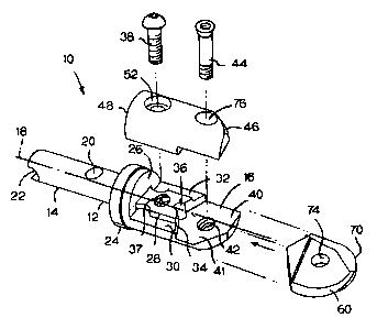
FIGURE 1 is an exploded view of a tool holder and a cutting insert
illustrating the preferred embodiment of the invention;
FIGURE 2 is a plan view of the tool holder showing the inside edge of
the V-shaped seat;
FIGURE 3 is an enlarged view as seen along lines 3-3 of Figure 2;
FIGURE 4 is a view of the inner face of the removable clamping
component;
FIGURE 5 is an enlarged view as seen along lines 5-5 of Figure 4;
FIGURE 6 is an enlarged longitudinal sectional view of the cutting tool
clamped to the tool holder body;
FIGURE 7 is a view of the cutting insert;
FIGURE 8 is a sectional view of the cutting insert; and
FIGURE 9 is an enlarged view of ramming screw in the insert opening.
Description of the Preferred Embodiment
Referring to the drawings, Figure 1 illustrates a preferred tool holder 10
comprising an elongated body 12 having a shank 14 at one end and a cutter
head 16 at the opposite end.
The shank is adapted to be held in a rotating drive means, not shown,
for rotation about a longitudinal axis 18. A recess 20 and a slot 22 provide
means for connecting the toot holder to the drive means in a manner
3

CA 02487463 2004-11-15
described in my U.S. Patent No. 5,468,102. Other shank configurations can
be used.
The shank is integrally attached to a collar 24 having a planar mounting
face 26. Axis 18 is perpendicular to the plane of face 26.
The components of the preferred tool holder are made of suitable steel
alloys adapted for the particular metal cutting application to which they are
to
be applied.
Referring to Figures 1 and 3, the cutter end of the tool holder has a
ridge 28 extending longitudinally from face 26, and a pair of flat mounting
surfaces 30 and 32 disposed in a common plane on opposite sides of ridge
28, and at right angles to face 26. Ridge 28 and mounting surtaces 30 and 32
terminate in a concave V-shaped seat 34. Seat 34 has an apex 36 adjacent
rotating axis 18 of the body.
Referring to Figure 2, ridge 28 has a tapped hole 37 for receiving a
threaded fastener 38.
The outer end of the cutter head forms a clamping component 40 with
a clamping surface 41 disposed in a plane that is parallel to mounting
surfaces 30 and 32. Clamping surface 41 is recessed from mounting surfaces
30 and 32, about one-half the thickness of a cutting insert. Surface 41 has a
tapped hole 42 for receiving a ramming screw 44. The finro tapped holes 37
and 42 are disposed along parallel axes and at right angles to mounting face
41. Mounting face 41 is disposed in a plane that is at right angles to face
26.
4

CA 02487463 2004-11-15
Referring to Figures 1 and 4, a removable second clamping component
46 is mounted on body 12 in abutment with clamping component 40. End face
48 abuts mounting face 26 of the collar.
Clamping component 46 has a longitudinal slot 50 that closely receives
ridge 28 to prevent any lateral shifting between the two clamping components.
Clamping comment 46 also has a fastener-receiving through-hole 52
aligned with tapped hole 37 for receiving fastener 38 to tightly connect the
two
clamping components together.
Referring to Figure 4, removable clamping component 46 has a pair of
flat mounting surfaces 54 and 56, disposed in a common plane, on opposite
sides of slot 50. The inner end of mounting surfaces 54, 56 and slot 50
terminate in a V-shaped concave seat 58 for receiving a cutting insert 60.
When clamping component 46 is mounted on clamping component 40,
mounting surfaces 30 and 32 abut mounting surfaces 56 and 54, respectively.
Fastener 38 connects the two clamping components together.
V-shaped seat 58 on clamping component 46 is aligned with V-shaped
seat 34 to form slot 64. Face 66 on removable clamping component 46 and
face 68 on clamping component 40 are parallel to one another and spaced to
tightly receive cutting insert 60.
Referring to Figures 1, 7 and 9, insert 60 has an outer cutting edge 70
which extends beyond the end of the cutter head. The insert has an inner end
with a V-shaped convex edge 72 seated in V-shaped seats 34 and 58. The
insert has a central through-hole 74 having an axis 75 slightly offset from
axis
75a in threaded hole 42 and frustoconical hole 76.
5

CA 02487463 2004-11-15
Referring to Figures 6-8, hole 76 is tapered from an elongated outer
opening 80 to an annular enlargement 82. Caroming screw 44 has a head 86
with a diameter less than the diameter of outer opening 80. The underside 88
of the ramming screw head is also frustoconical, but slightly smaller than
tapered hole 76 so that a small clearance exists permitting the ramming
screw to move in the direction 90.
The lower threaded end of the ramming screw is slightly smaller than
the threads of hole 42 to provide a small clearance permitting ramming
midsection 92 to slightly move in direction 90. Smooth, cylindrical ramming
midsection 92 abuts the inner end of insert through-hole 74.
The caroming screw is turned in the direction of arrow 94 until the
underside of the ramming screw engages the right side of frustoconical hole
76, as viewed in Figure 6. Turning the ramming screw further causes the
ramming screw head to slide down tapered hole 76, moving ramming
midsection 92 in the direction of arrow 90. This movement of the ramming
screw biases the insert toward a locked position in abutment with V-shaped
seats 34 and 58.
Further, as the head of the ramming screw head slides down tapered
hole 76, the ramming screw head sandwiches that portion of clamping
component 46 between the ramming screw head and the insert in area 98 to
further lock the insert in slot 64.
Turning the ramming screw in the opposite direction releases the insert
so the ramming screw can be removed, and then the insert removed from slot
64.
6

CA 02487463 2004-11-15
Thus it is to be understood that I have described an improved milling
tool holder in which the cutting insert is clamped at the outer end of the
tool
holder. The two clamping components have a mating ridge and slot to
prevent any lateral movement of one of the components with respect to the
other. The insert is biased against V-shaped seat in the two clamping
components. The V-shaped seat may take other cor~fgurations so long as
the configuration prevents the insert from being rotated with respect to the
tool
holder.
Having described my invention, I claim:
7

Representative Drawing
A single figure which represents the drawing illustrating the invention.
Administrative Status

2024-08-01:As part of the Next Generation Patents (NGP) transition, the Canadian Patents Database (CPD) now contains a more detailed Event History, which replicates the Event Log of our new back-office solution.

Please note that "Inactive:" events refers to events no longer in use in our new back-office solution.

For a clearer understanding of the status of the application/patent presented on this page, the site Disclaimer , as well as the definitions for Patent , Event History , Maintenance Fee  and Payment History  should be consulted.

Event History

Description Date
Application Not Reinstated by Deadline 2014-07-09
Inactive: Dead - Final fee not paid 2014-07-09
Deemed Abandoned - Failure to Respond to Maintenance Fee Notice 2013-11-15
Deemed Abandoned - Conditions for Grant Determined Not Compliant 2013-07-09
Notice of Allowance is Issued 2013-01-09
Letter Sent 2013-01-09
Notice of Allowance is Issued 2013-01-09
Inactive: Approved for allowance (AFA) 2012-12-24
Letter Sent 2012-09-21
Reinstatement Requirements Deemed Compliant for All Abandonment Reasons 2012-09-12
Inactive: Office letter 2012-02-01
Deemed Abandoned - Failure to Respond to Maintenance Fee Notice 2011-11-15
Amendment Received - Voluntary Amendment 2011-11-04
Inactive: S.30(2) Rules - Examiner requisition 2011-05-06
Inactive: Office letter 2009-11-19
Small Entity Declaration Determined Compliant 2009-11-04
Small Entity Declaration Request Received 2009-11-04
Small Entity Declaration Determined Compliant 2009-09-13
Request for Examination Requirements Determined Compliant 2009-09-13
All Requirements for Examination Determined Compliant 2009-09-13
Inactive: Correspondence - Formalities 2009-09-13
Request for Examination Received 2009-09-13
Letter Sent 2007-12-12
Letter Sent 2007-10-25
Application Published (Open to Public Inspection) 2006-01-02
Inactive: Cover page published 2006-01-01
Inactive: IPC assigned 2005-02-18
Inactive: First IPC assigned 2005-02-18
Inactive: Filing certificate - No RFE (English) 2005-01-08
Application Received - Regular National 2005-01-08

Abandonment History

Abandonment Date Reason Reinstatement Date
2013-11-15
2013-07-09
2011-11-15

Maintenance Fee

The last payment was received on 2012-09-14

Note : If the full payment has not been received on or before the date indicated, a further fee may be required which may be one of the following

  • the reinstatement fee;
  • the late payment fee; or
  • additional fee to reverse deemed expiry.

Patent fees are adjusted on the 1st of January every year. The amounts above are the current amounts if received by December 31 of the current year.
Please refer to the CIPO Patent Fees web page to see all current fee amounts.

Fee History

Fee Type Anniversary Year Due Date Paid Date
Application fee - standard 2004-11-15
MF (application, 2nd anniv.) - standard 02 2006-11-15 2006-07-06
MF (application, 3rd anniv.) - standard 03 2007-11-15 2007-11-02
MF (application, 4th anniv.) - standard 04 2008-11-17 2008-06-26
MF (application, 5th anniv.) - standard 05 2009-11-16 2009-08-28
Request for examination - small 2009-09-13
MF (application, 6th anniv.) - standard 06 2010-11-15 2010-10-19
2012-01-11
Reinstatement 2012-09-12
MF (application, 7th anniv.) - standard 07 2011-11-15 2012-09-12
MF (application, 8th anniv.) - standard 08 2012-11-15 2012-09-14
Owners on Record

Note: Records showing the ownership history in alphabetical order.

Current Owners on Record
STOJAN STOJANOVSKI
Past Owners on Record
None
Past Owners that do not appear in the "Owners on Record" listing will appear in other documentation within the application.
Documents

To view selected files, please enter reCAPTCHA code :


To view images, click a link in the Document Description column (Temporarily unavailable). To download the documents, select one or more checkboxes in the first column and then click the "Download Selected in PDF format (Zip Archive)" or the "Download Selected as Single PDF" button.

List of published and non-published patent-specific documents on the CPD .

If you have any difficulty accessing content, you can call the Client Service Centre at 1-866-997-1936 or send them an e-mail at CIPO Client Service Centre.

({010=All Documents, 020=As Filed, 030=As Open to Public Inspection, 040=At Issuance, 050=Examination, 060=Incoming Correspondence, 070=Miscellaneous, 080=Outgoing Correspondence, 090=Payment})


Document
Description 
Date
(yyyy-mm-dd) 
Number of pages   Size of Image (KB) 
Description 2004-11-14 7 236
Abstract 2004-11-14 1 13
Claims 2004-11-14 6 183
Drawings 2004-11-14 2 47
Representative drawing 2005-12-06 1 10
Description 2011-11-03 10 374
Claims 2011-11-03 5 182
Filing Certificate (English) 2005-01-07 1 158
Reminder - Request for Examination 2009-07-15 1 115
Courtesy - Abandonment Letter (Maintenance Fee) 2012-01-09 1 172
Notice of Reinstatement 2012-09-20 1 163
Commissioner's Notice - Application Found Allowable 2013-01-08 1 162
Courtesy - Abandonment Letter (NOA) 2013-09-02 1 164
Courtesy - Abandonment Letter (Maintenance Fee) 2014-01-09 1 172
Correspondence 2007-10-24 1 21
Fees 2007-10-11 1 27
Correspondence 2007-12-11 1 13
Fees 2007-10-11 1 26
Correspondence 2007-11-01 1 26
Correspondence 2009-09-12 2 63
Correspondence 2009-11-18 2 27
Correspondence 2009-11-03 2 46
Correspondence 2012-01-31 1 19
Fees 2012-01-10 1 25