Note: Descriptions are shown in the official language in which they were submitted.
CA 02487827 2004-11-29
Description
Check Rail Device
The invention relates to a check rail arrangement for a switch or
intersection, comprising a
grooved rail with a grooved rail head, a groove and a lip, a strip or
secondary rail extending along
the grooved rail, a check rail supported on at least the lip or machined lip
and arranged so as to
be adjustable relative to the grooved rail, a support element extending from
the grooved rail and
having an elongate receptacle extending transversely of the longitudinal
direction of the grooved
rail, in which elongate receptacle a fastening element is adjustably arranged,
from which extends
a first fastening means connected with or supported on the check rail
The purpose of check rails is to guide wheels in the area of switches or
intersections where there
is a gap. A corresponding arrangement is known from EP 0 830 480. A check rail
box extends
along the arrangement, fastening means such as bolts, by means of which the
check rail can be
fixed, are accessible to enable a readjustment or replacement. As a result,
the switch or
intersection requires a large-scale construction, so cost-related
disadvantages arise.
In a check rail arrangement according to DE 93 02 349 E1, a check rail is
supported both laterally
on the grooved rail foot and on the lip.
A check rail arrangement of the initially mentioned type is known from DE 297
19 799 U 1. In
this case, a check rail can be adjusted relative to a grooved rail by means of
a support element
in the form of a support plate extending from the grooved rail, which support
plate can be welded
to a profiled strip which has a slot, into which a nut for a bolt can be
inserted, extending
transversely of the longitudinal axis of the grooved rail, by means of which
bolt a check rail
profile supported on the lip of the grooved rail can be tightened.
A readjustable guide device is described in DE 296 09 572 U1. In this case, a
check rail is
adjusted and fixed by means of a bolt connection which can be fixed in a
groove formed between
transverse webs.
The object of the present invention is to form a check rail arrangement with
structurally simple
measures which should enable a problem-free adjustment of the check rail
without the need for
a check rail box. According to one aspect of the invention, it should also be
ensured that there
is a flush transition between the check rail and the lip of the grooved rail
in the end areas of the
check rail arrangement.
CA 02487827 2006-12-20
-2-
According to the invention, the object is essentially solved in that two
mutually adjustable
elements are associated with the check rail at the underside, the extent of
which is variable
transversely of the longitudinal direction of the grooved rail to the desired
extent, the one first
element being supportable against the check rail strip and the other second
element against the
secondary rail or an element associated with it. Preferably, the check rail is
connected at the
underside with a holder which is open at the secondary rail side and the first
element of the
mutually adjustable two elements is supported along a boundary of the holder
extending in the
longitudinal direction of the grooved rail and the second element is supported
at the secondary
rail or the element associated with it.
Also, the check rail is preferably fixed by means of fastening elements
(locking devices) which
are adjustable in elongate receptacles, which may be designated as slide
slots, extending
transversely of the longitudinal axis of the grooved rail, which fastening
elements are similar to
slide or slot blocks, whereby a desired adjustment of the check rail to form a
desired gap or slot
between grooved rail head and leading edge of the check rail occurs by means
of adjustment
mechanisms which are formed by mutually adjustable, in particular, wedge-
shaped elements, of
which one of the elements is supported on the check rail or on the holder
extending therefrom
and the other on the secondary rail or an element associated with it
(adjustment devices).
Consequently, a precise width setting is made possible without the need for
plates which are used
according to the prior art to align the check rail.
Fastening elements such as bolts, both for the locking devices and for the
adjustment devices,
are accessible from the top of the check rail without the need for a check
rail box or an opening
of an embedding. Moreover, the check rail strip can be loosened, readjusted
and fastened or
exchanged with conventional tools.
The holder, functionally open at the secondary rail side, may be described as
an open cage which
accommodates the first and second elements, which are supported on one another
in a wedge-like
manner and adjustable to one another in such a way that the overall size of
the elements can be
changed transversely of the longitudinal direction of the grooved rail to the
desired amount, one
of the elements, as already mentioned, being supported directly or indirectly
at the secondary rail
and the other element at the boundary or wall of the cage extending in
longitudinal direction of
the grooved rail.
When adjusting the first and second elements relative to one another, they are
supported on
surfaces extending a wedge-like manner. Furthermore, the first element, facing
away from the
check rail, is connected with the second fastening means, such as the lock
bolt, so that when it
is tightened the first element is adjusted in direction of the check rail,
with the result that the
CA 02487827 2004-11-29
-3-
second element supported on the surfaces of the first element extending in a
wedge-like manner
yields laterally and thus pushes away the holder fixedly connected to the
check rail, i.e. the cage
from the secondary rail, with the result that the groove between the leading
edge of the check rail
and rail head narrows.
In particular, the holder is U-shaped, the first element being supported on
its transverse portion
so as to be vertically adjustable. The upper second element, extending on the
secondary rail,
extends in turn through the holder between its side arms so as to be supported
on the secondary
rail.
Preferably, the first element has a quadrangular geometry with a T-shaped
surface in plan view,
a first rectangular surface extending along the transverse portion of the
holder and triangular
surfaces extending along the lateral sides of the holder, a second rectangular
surface of a smaller
width extending parallel to the first rectangular surface and a T-shaped
undersurface, the
respective triangular surface being the outer boundary of a respective first
wedge-shaped section
of the first element, on whose free outer surfaces, extending at an
inclination to the surface of the
first element, a second wedge-shaped section of the second element is
supported.
Furthermore, the first wedge-shaped sections of the first element delimit a
central quadrangular
section which has a bore with an internal thread for interaction with the
second fastening
element, i.e. the adjustment bolt.
The second element has a U-geometry with sloping or wedge-shaped side arms
which are
supported on the first wedge-shaped sections of the first element.
It is possible, with structurally simple measures, to adjust the check rail
strip towards and away
from the grooved rail head by means of this wedge mechanism in order to set
the width of the
groove between the leading edge and grooved rail head.
To ensure a flush transition between the leading edge of the check rail and
the lip of the grooved
rail or a corresponding structural profile in the end region, a further
embodiment of the invention
provides that, as viewed in the longitudinal direction of the grooved rail, at
the respective end of
the check rail, a guide plate extending between the secondary rail and the lip
and supported
thereon is associated with the check rail, the width of the guide strip being
such that the leading
edge of the check rail merges smoothly with the inner surface of the lip of
the grooved rail. The
guide plate and the check rail are thereby penetrated by a common fastening
means, such as a
bolt, which is secured by a lock nut. As a result, there can be no relative
movement between
guide plate and check rail transversely of the longitudinal direction of the
grooved rail, so that,
by the fixing via the guide plate, the check rail can be adjusted relative to
the lip of the grooved
CA 02487827 2004-11-29
-4-
rail such that its leading edge merges with the inner surface of the lip in a
flush manner. The first
element of the wedge mechanism, which is used to adjust the check rail, can
also be used as a
lock nut.
The check rail can be supported both on the machined lip of the grooved rail
or another structural
profile and the secondary rail or strip. Lip and secondary rail are thus
supports for the check rail
which has, in particular, a strip geometry whose narrow sides extend at the
grooved or secondary
rail side. Thus, a narrow side forms a leading edge of the check rail.
In particular, the check rail comprises a wear-resistant flat material in
which bores are integrated
which are penetrated by first or second fastening means such as bolts in
order, on the one hand,
to fix the check rail (lock bolts) and, on the other hand, to adjust the check
rail to the desired
extent in the direction of the grooved rail head to obtain a desired groove
width (adjustment bolt).
According to the invention, a separation between adjustment of the check rail
and fixing of the
check rail more or less occurs. In particular, the adjustment takes place by
means of a wedging
mechanism, whereas the fixing takes place by means of slide blocks which are
preferably
displaceable in slide slots. In this case, the fastening means, such as bolts,
which interact with
the slide blocks or the wedge mechanisms, extend from the upper side of the
check rail and are
thus easily accessible. It is thereby not necessary for the bolts to pass
through elongate holes,
whereby otherwise the danger of dirt deposits would exist to such a degree
that a simple
loosening of the bolt is no longer possible.
The elongate receptacle in the support element, which may in particular be a
filler piece,
extending between the grooved rail and the secondary rail is, as mentioned,
formed particularly
as a groove to receive a T-shaped slide block, which is the fastening element
for the check rail.
Other geometries for adjusting the fastening element along the elongate
receptacle or groove,
without an uncontrolled slipping out being possible, are also feasible. Thus,
a dove-tailed
geometry can also be selected.
The first fastening means, as lock bolts, pass through the check rail and are
screwed into the
fastening element or slide block in order to thereby fix the check rail by
tightening of the
fastening means. The head of the fastening means thereby extends in a recess
of the check rail
and is supported against it. The recess, which extends from the outer surface
of the check rail
is, in particular, a hole having a circular geometry, such that the space
between the head of the
bolt and boundary of the recess is determined by the size of a tool which is
to grip the bolt head,
so that only a limited accumulation of dirt is possible.
To reduce the moment of resistance of the check rail strip during bending,
that is when the
CA 02487827 2004-11-29
-5-
groove width is to be reduced, according to our own inventive proposal, slots
extend from the
longitudinal edge of the check rail at the side facing away from the grooved
rail, i.e. on the
secondary rail side, extend transversely of the longitudinal direction of the
rail. The slots can
then be covered by plates which are fixed by means of the first or second
fastening means.
Depending on the length of the check rail arrangement, a plurality of locking
and adjustment
units are accordingly provided for fixing and adjustment the check rail strip.
Accordingly,
several filler pieces are present which have a through opening at the
underside. This makes it
possible for any accumulated water to be able to flow along an underlying
plate, from which the
grooved rail and the secondary rail extend, to an opening of a drainage box.
Furthermore, the check rail arrangement is covered at the ends by closure
plates. Thus, an
outwardly closed system is available, so that contaminations in the area
between secondary rail
and grooved rail below the check rail can be avoided.
With respect to the secondary rail, also referred to as a strip, it should be
noted that it can consist
of flat material extending along the grooved rail, which can be connected,
e.g. welded, at the
bottom to a plate forming a rail foot. This foot extends at the side facing
away from the grooved
rail. Both the grooved rail and the secondary rail can be arranged e.g. on
concrete ties with an
insulated Napla rail fastening. Other known arrangements are also feasible.
The filler piece and the bolt connection connecting the grooved rail or its
web and the secondary
rail can be a high-tensile bolt which is secured e.g. with Nordlock plates.
Preferably, high-tensile
M27 bolts are suitable. The lock bolt should also be secured by means of
Nordlock washers.
The adjustment bolts, in turn, should be positively secured by washers which
are bent on one or
more flat faces of the bolt heads.
Further details, advantages and features of the invention can be found not
only in the claims, the
features found therein - alone and/or in combination - but also in the
following description of a
preferred embodiment found in the drawings, in which:
Fig. 1 shows a plan view of a check rail arrangement,
Fig. 2 shows a section along the line A-A in Fig. 1,
Fig. 3 shows a section along the line A'-A' in Fig. 1,
Fig. 4 shows a section along the line B-B in Fig. 1,
CA 02487827 2007-12-13
-6-
Fig. 5 shows a section along the line C-C in Fig. 1,
Fig. 6 shows a section along the line D-D in Fig. 1,
Fig. 7 shows a plan view of an adjustment unit,
Fig. 8 shows a front view of a holder of the adjustment unit according to Fig.
7,
Fig. 9 shows a plan view of a first element of the adjustment unit,
Fig. 10 shows a side view of the first element,
Fig. 11 shows a top view onto a second element of the adjustment unit
according to Fig. 7,
Fig. 12 shows a side view of the second element, and
Fig. 13 shows a section along the line E-E in Fig. 7.
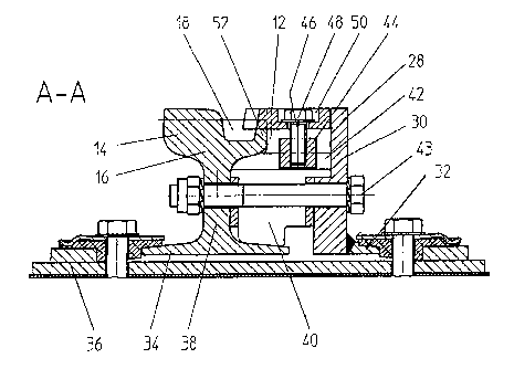
A check rail arrangement 10 intended for a switch or intersection of a grooved
rail track can be
seen in the figures, wherein a strip-shaped check rail 12 can be adjusted.
relative to a head 14 of
a grooved rai116 or a structural profile with a groove, to form a slot 18 of
the desired width. The
slot 18 should thereby be narrower in the middle region L3 than in the
respective end regions (L2,
L4) of the check rail arrangement 10.
To securely fix the check rail 12, referred to hereinafter as a check rail
strip, while simultaneously
enabling the desired adjustment, the check rail arrangement 10 comprises, on
the one hand,
locking units 20, 22 and, on the other hand, adjustment units 24, 26. The same
reference
numerals are basically used for the same elements in the description.
As can be seen in particular in the cross-sectional drawings, a secondary rail
28 or a similarly
acting element extends along the grooved rail 16, consisting of a flat
material extending along
the grooved rail 16 as first section 30 and a welded plate 32 forming a foot,
the plate 32
extending along the side of the base plate 36 facing away from the grooved
rail. In this
embodiment, secondary rai128 or its foot 32 and grooved rail 16 or its foot 34
are arranged on
concrete ties with insulated Nabla rail fastening which, in turn, extends from
a base plate 36 that
extends on the concrete tie.
CA 02487827 2007-12-13
-7-
Filler pieces 40, which are each connected or clamped together by means of a
bolt connection
43, are provided in the region of the locking units 20,22 extending between
the grooved rail 16
or its web 38 and the first section 30 of the secondary rail 28. In
particular, the bolt connection
is a high-tensile bolt such as M27 bolts which are secured by means of
Nordlock (trade-mark)
washers. However, in this respect, reference is made to known constructions.
At the check rail strip side and extending from the top surface, a slot 42
extends in the filler piece
40 transversely of the longitudinal direction of the grooved rail, in which
slot there is slidably
arranged a fastening means in the form of a slide block 44, which is guided
securely in the slot
42 due to its geometry, e.g. a T-shaped or dove-tailed geometry. The slide
block 44 has a boring
with an internal thread to receive a first fastening means in the form of a
bolt 46 (lock bolt), the
head 48 of which extends in a recess, such as a boring 50, extending from the
surface of the
check rail strip 12. By shifting the slide block 44 along the slot 42, the
check rail strip 12 can
therefore be adjusted toward the rail head 14 or away from it in order to
thereby adjust the width
of the groove 18.
As can be seen in the drawings, the check rail strip 12 is supported, on the
one hand, on the
machined lip 52 of the grooved rail 16 and, on the other hand, by the
secondary rai128, which
each form a support surface for the check rail strip 12. In this way, the
check rail strip 12 is fixed
in a form-locking manner on the respective support surface when the bolt 46 is
tightened.
By means of the locking units 20,22, it possible to adjust the check rail
strip 12 without the bolts
46 passing through elongate holes, which would become dirty and thus make
handling more
difficult.
As can be seen in the plan view of Fig. 1, several locking units 20, 22 are
provided depending
on the length of the check rail arrangement 10, and likewise the adjustment
units 24, 26, to be
described in the following, which make it possible to adjust the check rail
strip 12 in a controlled
manner to the required degree. To facilitate this adjustment, i.e. to reduce
the moment of
resistance of the check rail strip 12 against bending, slots 56, 60, extending
transversely of the
longitudinal axis of the check rail strip 12, extend from the longitudinal
edge 54 located at the
secondary rail side. A corresponding slot 56 can be seen in Fig. 3. The slots
can thereby be
covered by rust-proof plates which are, in turn, secured by bolts 46 or second
fastening means
in the form of adjustment bolts 58 extending from the adjustment units 24, 26.
These will be
described in greater detail with reference to Figs. 5 and 7 to 12 and with
reference to the
adjustment unit 26.
The adjustment unit 26 comprises a U-shaped cage 61 which extends from the
underside of the
check rail strip 12 and is, in particular, welded to it. The cage 61 is open
toward the secondary
CA 02487827 2004-11-29
-8-
rail 28 or a similarly acting element, the transverse portion 62 of the U-
profile extending parallel
or essentially parallel to the secondary rail 28 and thus to the grooved rail
16. Side arms 64, 66
extend at a right angle to the transverse portion 62.
An insert, comprising a first element 70 and a second element 72, is movable
within the cage 61
in its axial direction, i.e. along its longitudinal axis 68. The first and
second elements 70 and 72
co-operate in the manner of a wedge mechanism, so that, depending on the
relative positions of
the first and second elements 70, 72, the effective width of the insert can be
adjusted along
transverse axis 74 of the cage 61 and thus transversely of the grooved rail 16
or secondary rail
28.
Consequently, the check rail strip 12 can be shifted to the desired extent in
direction of the
grooved rail 16 or its head 14 since the first element 70 is supported by its
first outer surface 76
on the transverse portion 62 of the cage 61 and the second element 72 by its
outer surface 78 on
the secondary rail 28 or a corresponding element extending along the grooved
rail 14.
The first element 70 and the second element 72 thereby lie against one another
at wedge - or
ramp-shaped surfaces 80, 82 or 84 extending at an inclination to the
longitudinal axis 68 and thus
slide relative to one another, on axial displacement of the first element 70
towards the second
element 72, in such a way that there is a change in the distance between the
outer surfaces 76 and
78 of the first and second elements 70 and 72, so that the desired bending of
the check rail strip
12 is made possible.
As can be seen in the drawings, the first element 70 consists of a
quadrangular base section 86
which is penetrated by a boring 88 having an internal thread. The wedge-shaped
first sections
90, 92, forming the support surfaces 80, 82, extend laterally of the
quadrangular section 66. In
a plan view, the first element 70 is T-shaped.
The second element 78 exhibits a U-geometry, its transverse portion 94 at its
outer surface
(surface 78) abutting the secondary rail 28. The side arms 96, 98 have a
triangular geometry in
longitudinal section, the undersides forming the surfaces 84 which are
supported on the surfaces
80, 82 of the first element 70.
The insert formed by the first and second elements 70, 72 can be axially
adjusted relative to the
cage 61 simply due to the fact that an adjustment bolt 58 passing through the
check rail strip 12
engages in the internal thread of the boring 88 of the first element 70. In
this way, the effective
extent of the unit in the cage 61 can be adjusted as desired, transversely of
the longitudinal axis
of the check rail unit, and the distance between the first and second elements
70, 72 or their outer
surfaces 76, 78 can thereby be modified.
CA 02487827 2004-11-29
-9-
The angle of inclination a of the surfaces 80, 82, on the one hand, and 84, on
the other hand,
which are supported on one another, should be in the range of 50 <_ a< 70 ,
in particular a being
about 60 .
To ensure that the check rail strip 12 at its leading edge merges smoothly
with the inner surface
of the lip 52 at the respective end region (line 101), a plate element 100 is
provided, as shown
in the cross-sectional view B-B (Fig. 4), which is supported, on the one hand,
on the outer surface
of the lip 52 of the grooved rail 16 and, on the other hand, at the secondary
rail 28, i.e. on its
surface facing the grooved rail 16. The check rail strip 12 is connected with
the plate element
100 by a connecting means such as a bolt and a lock nut or a similarly acting
element such that
a relative movement between them, transversely of the longitudinal direction
of the grooved rail
16, is prevented. In this way, the check rail strip 12 can be located,
relative the grooved rail 16,
by the position of the opening in the plate element 100 through which the bolt
extends, in such
a way that the leading edge of the check rail strip merges smoothly with the
inner surface of the
lip 52.
Preferably, the plate element 100 extends in the region of a cage 61 and
passes through an recess
102 in its transverse portion 62. Furthermore, the plate element 100 is
penetrated by the
adjustment bolt 58, which engages in the first element 70, which, however, as
in the cross-
sectional view of Fig. 4, is rotated through 180 , in comparison to the
arrangement of Figs. 5 and
7 to 12, in order to act as a lock nut. This is also shown by the extent of
the sloping section 90,
which is illustrated by a broken line.
To ensure a drainage of the check rail arrangement 10, a conventional drainage
box 104 is used
which, by means of a funnel-shaped connection 108, receives water flowing
through openings
106 in the bottom of the filler piece 40 and along the base plate 36.
The lock bolts 46 for fastening the check rail strip 12 are preferably secured
by Nordlock
washers. The adjustment bolts 58 are, in turn, secured in a form-locking
manner by washers
which are bent at at least one flat face of the bolt heads.
Furthermore, closure plates 110, 112 should extend from the front surface of
the secondary rail
28 to the grooved rail 16 in order to obtain a closed system between grooved
rail 16 and check
rail strip 12 and secondary rai128.