Note: Descriptions are shown in the official language in which they were submitted.
CA 02487910 2004-11-18
1
FIELD OF THE INVENTION
The present invention relates to spectacles, and more particularly to a
hinge for spectacles.
BACKGROUND OF THE INVENTION
It is known to provide flexible resilient members to link the temples of
spectacles to the front frame thereof. These flexible resilient members allow
a hinged
attachment of the temples to the spectacle frame, thus allowing the temples to
be pivoted
between an inward stored position in which the temples extend parallel to and
along the
frame, and an operative position in which the temples extend perpendicularly
to and
away from the frame to engage the wearer's head above his ears. The flexible
resilient
hinges have the advantage of further allowing the temples to be pivoted
outwardly away
from the spectacles frame beyond their operative position without damaging the
hinge.
This is useful in cases where the temples are accidentally moved beyond their
operative
position, to prevent the hinge, the temples and/or the frame from being
damaged.
These resilient hinges also offer a spring-back erect that will
continuously bias the temples towards the respective sides of the head of the
person
2 0 wearing the spectacles, which helps to securely hold the spectacles
against the wearer's
head. Some such spectacles with temples having this spring-back erect are
called sports
CA 02487910 2004-11-18
2
glasses due to the fact that they will hold on to the wearer's head even under
sudden
movements of the head such as those that occur during sporting activities.
SUMMARY OF THE INVENTION
The present invention relates to a hinge for use on spectacles of the type
comprising a front frame for carrying lenses and a pair of temples, said hinge
comprising:
- a first attachment device for attaching said hinge to a corresponding one of
the
temples;
- a second attachment device for attaching said hinge to said frame;
- a rigid intermediate portion;
- a first flexible resilient portion carrying said first attachment device and
attached
to said rigid intermediate portion; and
- a second flexible resilient portion carrying said second attachment device
and
attached to said rigid intermediate portion opposite said first resilient
portion.
In one embodiment, said first and second resilient portions are made of
a polymeric material having an intrinsic resiliency.
In one embodiment, said intermediate portion comprises a rigid metallic
piece extending between said first and second resilient portions and attached
thereto.
2 0 In one embodiment, said hinge further comprises a unitary flexible
resilient member defining first and second ends and reinforced with a rigid
element
CA 02487910 2004-11-18
3
fixedly attached to said unitary resilient member between and spaced from said
first and
second ends, with said first resilient portion being defined between said
first end and said
rigid element, with said second resilient portion being defined between said
second end
and said rigid element, and with said rigid intermediate portion being defined
at the
position of said rigid element.
In one embodiment, said first and second attachment devices comprise
tenon and mortise joint means for engagement with complementary tenon and
mortise
joint means provided on the temple and the frame, respectively.
In one embodiment, said hinge further comprises a pair of grooves each
provided on either side of and adjacent said intermediate portion allowing
said first and
second resilient portions to collapse towards and against said intermediate
portion.
The present invention further relates to spectacles comprising a front
frame for carrying lenses, a pair of temples and a pair of hinges each linking
a
corresponding one of said temples to said frame, each said hinge comprising:
- a first attachment device attaching said hinge to a corresponding one of
said
temples;
- a second attachment device attaching said hinge to said frame, whereby said
temple is hingedly attached to said frame;
- a rigid intermediate portion;
2 0 - a first flexible resilient portion carrying said first attachment device
and attached
to said rigid intermediate portion; and
CA 02487910 2004-11-18
a second flexible resilient portion carrying said second attachment device and
attached to said rigid intermediate portion opposite said first resilient
portion;
wherein each said temple can be pivoted with its corresponding said hinge
relative to
said frame between a stored position in which said temple is unbiased by said
hinge and
in which said temple is pivoted adjacent to said frame; an operative position
in which
said temple is pivoted away from said frame, is substantially perpendicular to
said frame
and is biased towards said stored position under the effect of a first spring-
back biasing
force exerted by said first and second resilient portions; and a spread out
position in
which said temple is pivoted outwardly away from said frame beyond said
operative
position and is biased towards said stored position under the effect of a
second spring-
back biasing force exerted by said first and second resilient portions, with
said second
spring-back biasing force being greater than said first spring-back biasing
force.
DESCRIPTION OF THE DRAWINGS
In the annexed drawings:
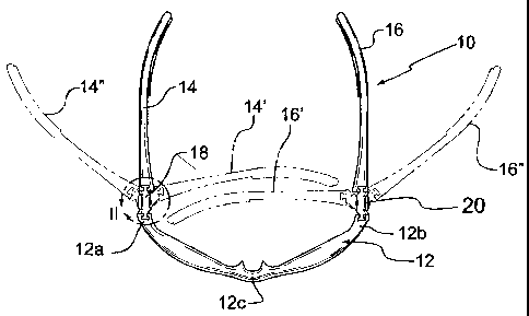
Figure 1 is a bottom plan view of the spectacles according to a first
embodiment of the present invention, showing the temples in full lines in
their operative
position, and further showing in phantom lines the temples in two alternate
positions,
namely in a stored and in a spread out position;
2 0 Figure 2 is an enlarged view of the area circumscribed by circle II of
figure 1;
CA 02487910 2004-11-18
Figure 3 is a partial top and front perspective view of the spectacles of
figure 1, including one temple, one hinge and part of the front frame;
Figure 4 is a partial top and rear perspective view at an enlarged scale of
the spectacles of figure 1, including one hinge and the adjacent parts of the
front frame
5 and corresponding temple;
Figure 5 is a cross-sectional view of the hinge only of the spectacles,
taken along line V-V of figure 4;
Figure 6 is similar to figure 4, but pertains to an alternate embodiment of
the invention; and
Figure 7 is an enlarged cross-sectional view of the hinge only of the
spectacles of figure 6, taken along line VII-VII of figure 6.
DETAILED DESCRIPTION OF THE EMBODIMENTS
Figures 1-5 show a first embodiment of spectacles 10 according to the
invention, that comprise a front frame 12 for carrying. lenses (not shown), a
pair of
temples 14, 16 and a pair of hinges 18, 20 each linking a corresponding one of
temples
14,16 to frame 12. Front frame 12 is of a conventional shape, and defines
opposite first
and second extremities 12a, 12b, a nose bridge 12c and first and second lens
openings
12d, 12e for carrying selected lenses therein. Frame 12 may be arcuate, as
illustrated,
2 0 or flat, or other suitable shape, such that frame 12 forms a general plane
adapted to fit
over the nose and ahead of the wearer's eyes.
CA 02487910 2004-11-18
6
Each hinge 18, 20, for example hinge 18 shown in figures 1-3 and 5,
comprises a first attachment device attaching hinge 18 to its corresponding
temple 14,
in the form of a tenon and mortise joint means that includes a tenon or cross-
sectionally
T-shaped lip 22 that engages a complementary tenon and mortise joint means in
temple
14 in the form of a mortise or cross-sectionally T-shaped slot 24 made in the
temple
extremity 14a attached to adjacent frame extremity 12a. It is understood that
the tenon
and mortise joint means could be inverted, i.e. the protruding lip could be
provided on
the temple and the slot could be provided on the hinge; and more generally,
any other
suitable male-female attachment device can be envisioned including for example
any
similar male and female dovetail interlock joint means, of various shapes, or
any suitable
adhesive or small bolts, provided they do not hamper pivotal capability of
temple 14
relative to frame 12 about hinge 18 as above noted.
Hinge 18 also comprises a second attachment device attaching hinge 18
to the corresponding extremity 12a of frame 12, in the form of a tenon and
mortise joint
means that includes a tenon or cross-sectionally T-shaped lip 26 that engages
a
complementary tenon and mortise joint means in frame 12 in the form of a
mortise or
cross-sectionally T-shaped slot 28 made in the frame extremity 12a attached to
temple
14. It is understood that the tenon and mortise joint means could be inverted,
i.e. the
protruding lip could be provided on the frame and the slot could be provided
on the
2 0 hinge; and more generally, any other suitable male-female attachment
device can be
envisioned including for example any similar male and female dovetail
interlock joint
CA 02487910 2004-11-18
7
means, of various shapes, provided they do not hamper pivotal capability of
temple 16
relative to frame 12 about hinge 18 as above noted, or any suitable adhesive
or small
bolts.
In the embodiment shown in figures 1-5, slots 24, 28 respectively made
in temple 14 and frame 12 are opened at the underside of spectacles 10 and are
close-
ended, in that they do not extend for the full height of temple 14 and frame
12.
Consequently, lips 22 and 26 can be upwardly slidably inserted in their
respective slots
24 and 28 from underneath, with lips 22, 26 abutting against the closed ends
of slots 24,
28. The engagement of lips 22, 26 in slots 24, 28 is preferably of the
friction fit type
engagement, to prevent lips 22, 26 from accidentally sliding our of slots 24,
28.
Hinge 18 also defines a rigid intermediate portion 30, a first flexible
resilient portion 32 carrying lip 22 and a second flexible resilient portion
34 carrying lip
26. More particularly, in the embodiment of figures 1-5, hinge 18 comprises a
unitary
resilient member 36 that extends between temple 14 and frame 12, including lip
22 at
a first end and lip 26 at a second end of resilient member 36. A rigid element
in the forth
of a rigid, flat, vertical metallic plate 38 is fixedly attached to unitary
resilient member
36 between and spaced from its first and second ends, facing outwardly of
spectacles 10.
2 0 The first resilient portion 32 is more particularly defined between rigid
plate 38 and the
resilient member first end at lip 22; the second resilient portion 34 is more
particularly
CA 02487910 2004-11-18
8
defined between rigid plate 38 and the resilient member second end at lip 26;
and the
rigid intermediate portion 30 is more particularly defined at the position of
rigid plate 38.
Rigid plate 38 is attached to the unitary resilient member 36 by means of a
pair of
screws 40 that are driven through resilient member 36 and into complementary
threaded
sockets 42 integrally attached to rigid plate 38 and that extend within holes
44 made
through resilient member 36 (see particularly figure 5).
Hinge 18 further comprises a pair of grooves 46, 48 made in resilient
member 36 and each provided on either side of and adjacent intermediate
portion 30,
facing outwardly of spectacles 10.
It is understood that hinge 20 is a minor image of hinge 18, and
consequently although hinge 20 is not detailed herein, it is understood that
the present
description of hinge 18 also applies to hinge 20.
In one embodiment, the first and second resilient portions 32, 34, of
hinges 18, 20, are made of a polymeric material having an intrinsic
resiliency, such as
rubber. One material which may be used is the thermoplastic elastomer sold
under the
registered trade-mark FORPRENE, by the company So.F.Ter. Spa located in Forli,
Italy.
In use, spectacles 10 are assembled by friction-fitting the lips 22, 26 of
hinges 18, 20 into the corresponding temple openings 24 and front frame
openings 28
respectively as described hereinabove, to hingedly attach temples 14, 16 to
front frame
12. More particularly, as suggested in figure 1, temples 14, 16 are hinged to
frame 12
in such a way as to allow temples 14, 16 to pivot between:
CA 02487910 2004-11-18
9
a) a stored position shown in phantom lines at 14', 16' in figure 1, in which
temples
14, 16, are pivoted towards and are positioned generally parallel to the
general plane of
front frame 12, and in which hinges 18, 20 are in a rest position (shown in
figure 5 for
example), i.e. hinges 18, 20 do not bias temples 14, 16 towards or away from
front frame
12;
b) an operative position shown in full lines at 14, 16 in figure 1, in which
temples
14, 16, are pivoted away from and are positioned generally perpendicular to
the general
plane of front frame 12 for engaging a wearer's head over his ears as known in
the art,
and in which hinges 18, 20 are in slightly compressed compared to their rest
position and
continuously bias temples 14, 16 towards their rest position due to the
intrinsic resiliency
of the hinge resilient portions 32 and 34, thus allowing for a more stable
engagement of
spectacles 10 on the wearer's head; and
c) a spread out position shown in phantom lines at 14", 16" in figure l, in
which
temples 14, 16, are pivoted outwardly away from their operative position and
yet further
away from frame 12, and in which hinges 18, 20 significantly bias temples 14,
16
inwardly towards their rest position.
It can be seen that each hinge 18, 20, for example hinge 18 as shown in
figure 5, is designed to promote the two-tiered biasing force distribution
suggested
hereinabove according to the angular position of its corresponding temple 14.
Indeed,
2 0 in the rest position of hinge 18, resilient member 36 naturally forms an
elbow with lips
22, 26 extending in divergent directions. Consequently, if no outside force is
exerted on
CA 02487910 2004-11-18
temple 14, it will adopt its stored position. This is desirable, since having
the temples
14, 16 extending along frame 12 in a stored position provides a more compact
shape to
spectacles 10 that favors easy storing thereof and reduces likelihood of
accidental
damage thereto.
5 However, as temple 14 is pivoted away from its rest position and towards
its operative position, 'resilient member 36 will bend, mainly at grooves 46,
48 that offer
a weaker resistance area on resilient member 36, with the first and second
resilient
portions 32, 34 collapsing towards rigid intermediate portion 30. The latter,
being
reinforced by rigid plate 38, will not compress. Thus, a first spring-back
biasing force
10 is then exerted on temple 14 by hinge 18, which first spring-back biasing
force is
calibrated to offer a desirable inwardly oriented pressure against a person's
head around
that person's ears when spectacles 10 are worn.
It is further desirable to allow temple 14 to be pivoted further outwardly
away from its operative position, for example into the spread out position
shown at 14",
16". In such an angular position of temple 14 outwardly beyond its operative
position,
the first and second resilient portions 32, 34 of hinge 18 have collapsed
against rigid
intermediate portion 30, and the angular displacement of temple 14 beyond its
operative
position is allowed by the compression of first and second resilient portions
32, 34
between the temple extremity 14a and the rigid plate-reinforced intermediate
hinge
2 0 portion 30. This compression of first and second resilient portions 32, 34
provides a
second spring-back biasing force which is greater than the above-mentioned
first spring-
CA 02487910 2004-11-18
11
back biasing force.
This second spring-back biasing force of greater value than that of the
first spring-back biasing force is desirable to ensure that temple 14 will
move back
towards the wearer's head with haste if it is accidentally pulled away, which
is especially
advantageous on sports glasses. However, one would not want such a powerful
spring-
back biasing force applied to temple 14 at all times since it would then
become
uncomfortable for the wearer of spectacles 10 who would feel considerable
pressure
against the sides of his head. Also, allowing temple 14 to pivot outwardly
beyond its
operative position into a spread-out position, is desirable since it prevents
hinge 18,
temple 14 and/or frame 12 from being damaged or broken if temple 14 is
accidentally
pulled outwardly away beyond its operative position.
It can be seen that throughout the pivotal displacement of temple 14 from
its operative position towards its spread out position, the hinge rigid
intermediate portion
30 will provide a seat against which first and second resilient portions 32,
34 may abut.
It is understood that grooves 46, 48 are facultative. In the absence of
grooves 46, 48, a resilient member 36 could be designed having a geometry
allowing for
a gradual increase of the spring-back biasing force exerted by hinge 18 as
temple 14 is
pivoted away from its stored position. The optimal angular value of temples
14", 16" at
their spread-out position is a large acute angle relative to their operative
position 14, 16,
2 0 generally perpendicular to frame 12, preferably between 30 and 60°,
and most preferably
about 45° .
CA 02487910 2004-11-18
12
Figures 6 and 7 show another embodiment of the present invention, which
is similar to the embodiment shown in figures 1-S except as noted hereinafter.
In the embodiment of figures 6-7, spectacles 100 comprise a hinge 102
linking the temple 104 to the front frame 106. Hinge 102, similarly to hinges
18, 20 of
the first embodiment, comprises a rigid intermediate portion 108 flanked by
first and
second flexible resilient portions 110, 112 located on either side of
intermediate portion
108. First and second resilient portions 110, 112 are respectively provided
with first and
second tenon and mortise joint means 114, 116 that cooperate with respective
complementary tenon and mortise joint means (not shown) provided on temple 104
and
on frame 106 for attaching hinge 102 to temple 104 and to frame 106, thereby
effectively
hingedly attaching temple 104 to frame 106.
According to the second embodiment of the invention, hinge 102
comprises an intermediate portion 108 made from a rigid metallic piece
extending
between first and second resilient portions 110, 112 and attached thereto by
means of
additional tenon and mortise joint means 118, 120. Thus, the hinge 102 of the
second
embodiment is not made of a unitary resilient member as per the first
embodiment, but
rather from a pair of distinct first and second resilient members that form
the first and
second resilient portions 110, 112, and from a rigid metallic piece attached
between and
linking the first and second resilient members.
CA 02487910 2004-11-18
13
Similarly to the first embodiment shown in figures 105, grooves 122, 124
may be provided on the outer surface (relative to the entire spectacles 100)
of hinge 102,
to facilitate the resilient pivotal displacement of temple 104 relative to
frame 106
between the stored position and the operative position of temple 104. However,
when
temple 104 reaches its operative position in which it extends substantially
perpendicularly to frame 106, first and second resilient portions 110, 112
have collapsed
and become seated against rigid intermediate portion 108 to increase the
elastic
resistance of any further outward pivotal displacement of temple 104 beyond
its
operative position towards a spread out position.
It has been found that with either type of the above noted embodiments
of hinges according to the present invention, an unexpectedly large increase
in resistance
to wear and in sturdiness were obtained. Accordingly, eyewear integrating
these temple
hinges should be much more longer lasting than prior art eyewear.
Any further modification obvious for someone skilled in the art is
considered to be included herein, as may be ascertained from the appended
claims.