Note: Descriptions are shown in the official language in which they were submitted.
CA 02488062 2004-12-O1
WO 03/104547 PCT/FI03/00447
1
SYSTEM FOR PRODUCING ENERGY AT A PULP MILL
In chemical pulp mills the cooking chemicals of a pulping process are
recovered from
black liquor by firing the black liquor in a recovery boiler alone or together
with other
"waste" streams. The firing process is exothermic and the released energy is
recovered
to as pressurized superheated steam. The steam energy is recovered in a steam
turbine
in form of electric power and low-pressure steam for process needs.
Traditionally, energy is produced in a pulp mill by combusting black liquor in
a recovery
boiler, and wood wastes and bark in an auxiliary boiler. The bark of the wood
raw
material and the organic substance of generated black liquor together normally
supply
the entire energy demand of the pulp mill. If more energy is needed in the
pulp mill,
additional fuel may be purchased. The additional fuel is combusted with the
wood bark
in the auxiliary boiler. Conventionally, energy is produced in a pulp mill in
the following
way: a recovery boiler and an auxiliary boiler, wherein waste wood bark from
the mill is
2o combusted to generate superheated high-pressure steam. The generated steam
is
forced through a backpressure steam turbines) and the released steam is used
to
provide heat for the mill. The turbine and a generator connected thereto
produce
electricity needed to power the mill.
Wood contains small amounts of potassium (K) and chlorine (CI). These elements
remain in the black liquor during cooking. In the recovery boiler, these
elements are
enriched into the fly ash and increase the corrosiveness of the flue gas
especially in the
superheater. The corrosiveness of CI and K increase with temperature. The
corrosiveness of CI and K impose an upper temperature limit on the steam
generated in
the recovery boiler. This limit for the superheated steam temperature is
typically 400°
3o to 490°C, depending on the content of chlorine and potassium. With
special materials
or with liquors having a very low CI and K content, steam temperatures up to
520°C
have been used. Because the corrosiveness of CI and K generally require the
temperature of the superheated steam to be held relatively low, the steam
pressure is
also low. These temperature limitations result in low power yield from the
heat
generated in the recovery boiler, as compared to normal power boilers fuelled
by coal,
natural gas or oil.
CA 02488062 2004-12-O1
WO 03/104547 PCT/FI03/00447
2
These temperature limitations on the steam in a recovery boiler are not as
strictly valid
with bark originating from logs, but the fly ash from bark combustion in a
bark boiler
may also contain chlorine and potassium. As the sulfur content of bark is very
low,
potassium reacts in the bark boiler with chlorine and forms KCI K and CI,
which in turn
may result in superheater corrosion. Calorimetric flow in bark is also much
lower than
to in the black ("waste") liquor flow, due to much lower mass flow.
New power cycles developed to replace the traditional recovery boiler and
steam
turbine cycle have been studied, and pressurized gasification of "waste"
liquor and bark
appears to have promising possibilities. However, much more development
appears to
be needed before these technologies have the necessary reliability and
performance.
Anyway, efficient systems have not, to the best of our knowledge, been
developed for
increasing the temperature and pressure of superheated steam produced at a
recovery
boiler plant of a pulp mill in such a way that no corrosion occurs or the rate
corrosion is
at acceptable levels. Thus, according to the present invention, a system is
provided for
2o increasing the power yield in energy production at a pulp mill so that
corrosion problems
can be minimized. A further object of the invention is to provide a compact
system, in
which heat is recovered efficiently when high temperature and high pressure
steam is
produced.
For achieving the objects mentioned hereinabove the invention relates to a
spent liquor
recovery boiler system comprising a boiler having a water/steam circulation
system
having superheaters and a furnace for recovering energy and chemicals from
spent
liquor combusted therein, the walls of the boiler being formed of a plurality
of water-
cooled tubes connected to the water/steam circulation system. It is a
characteristic
3o feature of the system according to the invention that the system is
provided with at least
one cavity having walls formed of water-cooled tubes connected to the
water/steam
circulation system of the recovery boiler, means for combusting a fuel and at
least one
outlet for discharging combustion gases to the boiler, the interior of the at
least one
cavity being provided with heat exchanger means for final superheating of the
steam
generated in the boiler, said heat exchanger means being connected to the
superheaters of the boiler.
CA 02488062 2004-12-O1
WO 03/104547 PCT/FI03/00447
3
According to the system of the invention at least one combustion cavity is
provided in
connection with a recovery boiler for the final superheating of steam produced
in the
superheater section of the recovery boiler. The system of the invention allows
that the
steam is heated in the conventional heat transfer sections (i.e. economizers,
boiler
bank, and superheaters) of the recovery boiler into such a degree that high
temperature
to corrosion does not substantially take place, i.e. below 520 °C,
optimally 480-500 °C,
and after that the steam is final superheated to 500-600 °C, optimally
to 520-560 °C in
the combustion cavity, which serves as a final superheater. The recovery
boiler system
can be provided with one or more final superheater (cavities). The fuel burned
in the
final superheater/s is such that it does not cause high temperature corrosion.
The walls of the superheater cavity are designed as water-cooled heat transfer
surfaces, which are connected to the main water/steam circulation system of
the
recovery boiler through connection pipes for the incoming water/steam-water
mixture
and outgoing water/steam-water mixture. Thus, the heat surfaces form a part of
the
2o main water system of the recovery boiler. The main water system and
consequently the
water system of the superheater cavity can be of natural circulation type or
forced
circulation or so called once-through, the last-mentioned being typical for
the highest
steam/water pressures. In natural circulation boilers this means that cooling
water is fed
via downcomers from a drum down to headers feeding the walls of the cavity or
cavities, and water-steam mixture from these walls is collected and fed into
the drum.
The cavity can have separate walls of its own, but part of the walls of the
cavity or part
of the walls of the cavities can be common with the "conventional" part of the
boiler.
The interior of the cavity is provided with heat exchanger means for heat
transfer from
3o the combustion gas produced in the cavity to the steam flowing in the heat
exchanger
means. The heat exchanger means serve as a final superheater for the steam
from the
superheater section of the recovery boiler.
The optimum location for the cavity is the front wall, which is opposite to
the "bullnose"
wall, but the cavity can be built on sidewalls too, either as one cavity, or
as several
ones. The location or locations of the cavity or the cavities can be in the
vertical
direction anywhere, in relation to the conventional part of the boiler,
limited only by the
cooling water circulation.
CA 02488062 2004-12-O1
WO 03/104547 PCT/FI03/00447
4
The superheater cavity for the final superheating of the recovery boiler steam
is heated
by burning fuel. A burner or burners for the fuel are located at the top of
the cavity, at
the bottom of the cavity, or on the walls of the cavity. The cavity can also
be located in a
horizontal position, when the most preferred location for the burner or the
burners is on
one end wall of the cavity.
to
The combustion air system of the superheater cavity is a part of the
combustion air
system of the recovery boiler. It may also have a separate air system with an
air fan of
its own, connection ducts between the fan and the burners) and any necessary
equipment for the combustion air control.
The superheater cavity for the final superheating of the recovery boiler steam
is heated
by burning fuel in such a manner that noncorrosive conditions in the
superheater cavity
are guaranteed. The fuel can be a gas produced by gasifying biomass. The
corrosion of
heat surfaces can be avoided by additional combustion of sulfurous fuel. Also
the
cleaning of the gas before the combustion in the superheater cavity guarantees
noncorrosive conditions at higher temperatures. Instead of the gas produced
from
biomass other fuels can be used, e.g. natural gas, LPG, liquefied biomass,
methanol,
etc. The criterion for the fuel is the noncorrosive nature under the cavity
conditions. The
fuel combustion in the cavity is normally complete with optimized amount of
excess air,
but stoichiometric or reducing conditions are also possible, if preferable.
The offgases of the superheater cavity are led into the recovery boiler,
preferably to the
inlet of the main superheater where they are mixed with the main gas stream
coming
from the boiler furnace. Other locations for the gas connection are possible
as well: the
3o whole area from the lower part of the furnace to the inlet of the
economizer. The offgas
connection through the boiler wall comprises preferably more than one opening.
The flue gases from the superheater cavity may be used to shape a flue gas
flow
pattern, from the furnace of the recovery boiler over the bull nose to improve
gas
distribution and heat transfer into the superheaters, or to generate
conditions required
for emission control, such as the optimum temperature window for selective non-
catalytic reduction (SNCR) to reduce NOX emissions, or for particle size
growth to
reduce fine particle (size less than 2.5 micrometers) emissions. Another
possibility is to
use these flue gases for shaping the flow pattern in the furnace to improve
mixing, e.g.,
CA 02488062 2004-12-O1
WO 03/104547 PCT/FI03/00447
5 introducing these gases via vertically located ports, as is described in
European patent
668,983 and in WO 02/081971, instead of air or mixed with air. Combustion in
the
superheater cavity may be performed also under sub-stoichiometric conditions.
Reduced gases thus generated can be introduced into flue gases from the
furnace to
reduce nitrogen oxide emissions in the flue gases coming from the furnace.
1o By means of the invention the pressure and the operating temperature of the
steam
recovered from the waste liquor recovery process is increased by means of the
superheater cavity, whereby the overall electrical efficiency of the plant is
improved, i.e.
more power is generated by the heat recovered in the steam. The system
according to
the present invention is preferably used in connection with the process
described in
international patent application PCT/F103/00358.
During the past years waste liquors from pulping were burned in a separate,
refractory
lined combustion chamber, which was connected to a recovery boiler. Flue gases
flowed from the combustion chamber into the furnace of the recovery boiler,
which was
2o equipped with oil or gas burners or with grates for bark and coal etc. In
these boilers the
separate combustion chamber was used to stabilize combustion, not to superheat
steam to the final high temperature from the superheaters of the upper part of
the
furnace of the boiler. An essential feature of the present invention is that
the
combustion cavity and the recovery boiler have a common water circulation
system.
US patent 2,606,103 describes a system, in which the walls of a separate
furnace are
cooled by air.
The invention will now be described in more detail with reference to the
accompanying
drawing, in which one embodiment of the invention is illustrated schematically
in Fig. 1.
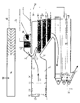
3o The reference numbers are as follows:
1. Conventional recovery boiler
2. Cavity
3. Furnace of the recovery boiler
4. Floor of the conventional boiler
5. Char bed in the conventional boiler
6. Primary air ports
7. Secondary air ports
CA 02488062 2004-12-O1
WO 03/104547 PCT/FI03/00447
6
8. Liquor spraying equipment
9. Tertiary air ports
10. Water-cooled furnace walls
11. Bullnose
12. Superheaters in the conventional boiler
l013. Boiler bank
14. Economizers
15. Flue gases leaving the boiler
16. Feedwater entering the boiler
17. Feedwater entering the drum in the described natural circulation
boiler
1518. Drum
19. Saturated steam entering the superheaters of the conventional
part of the boiler
20. Superheated steam from the conventional part of the boiler
entering the
superheater(s)
in
the
cavity
21. Live steam leaving the boiler
2022. Burner or burners in the cavity
23. Flame or flames in the cavity
24. Superheater or superheaters in the cavity
25. Headers of the cavity to feed cooling water from the drum
(18) to the walls of the
cavity
2526. Flue gas flow from the cavity
27. Flue gas flow from the furnace of the conventional boiler
28. Fuel feed to the gasifier
29. Gasifier
30. Gas to the burner or burners of the cavity
3031. Gas cleaning or other type treatment for gases leaving
the gasifier for other
purposes
than
for
the
cavity
(2)
32. Gas cleaning or other type treatment for gases leaving
the gasifier for the cavity
I-IIIsuperheaters in the conventional part of the boiler, and
IV superheater in the cavity
35 The furnace 3 of a typical recovery boiler, such as a soda recovery boiler,
used for the
combustion of black liquor, has a structure formed of a water-cooled bottom 4
and
water-cooled walls 10 made of a compact membrane structure, so that a water-
steam
mixture under pressure flows in the tubes. The water-steam generated in this
way is
superheated downstream of the furnace, typically in a conventional superheater
12
CA 02488062 2004-12-O1
WO 03/104547 PCT/FI03/00447
7
located in the shield of a "nose" above the furnace. In the superheater the
heat of the
flue gases 27 generated during combustion is recovered. Typically, a boiler
bank and
an economizer serve as the after-heat surface in the boiler, and after the
superheater
the flue gases are directed into the boiler bank 13 and economizers 14. The
generated
high-pressure steam is typically further directed eto a steam turbine in order
to produce
1o electricity and process steam needed at the mill.
The lower section of the furnace and the bottom 4 of the soda recovery boiler
are made
of water-cooled tubes, which constitute a part of the pressurized section of
the boiler.
Due to the structure of the bottom and the lower section of the furnace, there
is natural
circulation of water in the bottom tubes, i.e., the circulation is effected by
a difference in
density. The boiler water is thus led at a high pressure and at a temperature
of, for
example, about 300°C to a distributing header (not shown) below the
bottom of the
furnace, from which the water is distributed into the bottom and sidewall
tubes. In the
lower section of the furnace, the water flows first nearly horizontally or
obliquely
2o upwards in the bottom tubes towards the walls, and then further upwards
through the
wall tubes to the upper section of the boiler.
The invention is based on a recovery boiler, where steam pressure is such that
excessive corrosion does not take place, i.e. the saturation temperature in
water-steam
emulsion plus the temperature difference due to incoming heat flux from the
tube
surface into water is less than 400-500 °C, which is the tube surface
temperature.
The steam temperature can be increased over the typical figures by integrating
into the
conventional recovery boiler 1 a special combustion and heat transfer chamber
or
3o cavity 2. The steam is superheated in the conventional superheater part 12
to such a
degree that high temperature corrosion does not take place, e.g. 480-520
°C, optimally
480-500 °C and the rest of the superheating up to 500-600 °C,
optimally to 520-560 °C,
takes place in a superheater or in superheaters 24 in a special combustion and
heat
transfer cavity 2 integrated into the recovery boiler, where the fuel to be
burned in a
burner or burners 22 with flame or flames 23 is so clean that it does not
cause high
temperature corrosion. Flue gases 26 from the cavity 2 are introduced into the
flue gas
stream 27 of the recovery boiler. Preferably the flue gases from the cavity
are directed
through several openings in the wall of the recovery boiler.
CA 02488062 2004-12-O1
WO 03/104547 PCT/FI03/00447
8
The cavity 2 is a part of a conventional recovery boiler, so that the walls of
the cavity
are water-cooled as in the conventional part of the furnace, in the boiler
bank and in
other hot areas, and this cooling is integrated into the drum 18 or into the
drums of the
conventional boiler with natural circulation. In once-through type boilers
this integration
means that the walls of the cavity are cooled by the water or steam flows of
the once-
1o through system. Same type of integration with circulation water is also
valid for forced
circulation type recovery boilers, if this arrangement is used. The main
advantage is the
introduction of heat from the cooling of the cavity into the same pressure
water or steam
flow or flows as in the main flow of the "conventional" part of the recovery
boiler. Air for
the combustion can be taken from the "conventional" part of the recovery
boiler or the
cavity may be equipped with its own fans or compressors.
According to a preferred embodiment a combustion gas 30 for the cavity is
produced in
a gasifier 29 by gasifying biomass material 28. Then a part of the gases is
used in the
cavity as clean fuel 30 in the burner 22 to superheat the steam in the
superheater 24
(IV) and also for re-heating purposes. Part of the gases 33 is used for other
purposes at
the pulp mill. If this type of fuel is not available, other fuels like natural
gas, LPG, oil,
methanol, liquefied biomass etc can be used. The criterion for the fuel is the
noncorrosive nature under the cavity conditions. This noncorrosive nature can
be
created in the gas from gasification 29 by cleaning the gas in treatment 31 or
32.
The invention is not intended to be limited to the embodiment illustrated and
described
above but it can be modified and varied within the scope and spirit of the
invention as
defined by the following claims. The use of the system of the invention is not
limited to
the firing of a certain spent liquor, but it can be applied in connection with
several spent
liquors, such as spent liquors from a kraft pulping process and soda pulping
process.