Language selection

Search

Patent 2488486 Summary

Third-party information liability

Some of the information on this Web page has been provided by external sources. The Government of Canada is not responsible for the accuracy, reliability or currency of the information supplied by external sources. Users wishing to rely upon this information should consult directly with the source of the information. Content provided by external sources is not subject to official languages, privacy and accessibility requirements.

Claims and Abstract availability

Any discrepancies in the text and image of the Claims and Abstract are due to differing posting times. Text of the Claims and Abstract are posted:

  • At the time the application is open to public inspection;
  • At the time of issue of the patent (grant).
(12) Patent Application: (11) CA 2488486
(54) English Title: APPARATUS FOR RELEASE OF THIN COATED SHEETS FROM A ROLLER COATING MACHINE
(54) French Title: APPAREIL PERMETTANT DE PRODUIRE DES FEUILLES ENDUITES MINCES A PARTIR D'UNE MACHINE D'ENDUCTION A ROULEAUX
Status: Deemed Abandoned and Beyond the Period of Reinstatement - Pending Response to Notice of Disregarded Communication
Bibliographic Data
(51) International Patent Classification (IPC):
  • B05C 11/06 (2006.01)
  • B05C 1/08 (2006.01)
(72) Inventors :
  • WALKER, JAMES C. (United States of America)
  • MORA, ALFONSO A. (United States of America)
(73) Owners :
  • DORN SPE INCORPORATED
(71) Applicants :
  • DORN SPE INCORPORATED (United States of America)
(74) Agent: KIRBY EADES GALE BAKER
(74) Associate agent:
(45) Issued:
(22) Filed Date: 2004-11-25
(41) Open to Public Inspection: 2006-02-09
Availability of licence: N/A
Dedicated to the Public: N/A
(25) Language of filing: English

Patent Cooperation Treaty (PCT): No

(30) Application Priority Data:
Application No. Country/Territory Date
10/915,811 (United States of America) 2004-08-09

Abstracts

English Abstract


The present invention obviates the use of a vacuum while providing reliable
release of thin coated sheets from roller coating machines. Reliable release
of a
coated sheet is achieved by using dual sets of air nozzles, one set producing
a
constant flow of a sheet of air and the other producing a short pulse of a
sheet of air at
an appropriate time in the travel of the front edge of the sheet through the
rollers. An
optical sensor is employed to provide the properly timed signal to initiate
the pulsed air
blast. The respective sets of nozzles are configured to position the nozzles
in two
rows, one above the other, with offset or alternating horizontal positioning
so that
nozzles of one set do not interfere with nozzles of the other set. Each set of
nozzles is
connected to a common plenum or air bar extending in parallel relation to the
rollers.
Each such plenum or air bar is connected to an air pressure source by suitable
regulators, filters, solenoids, valves, hoses and connectors.


Claims

Note: Claims are shown in the official language in which they were submitted.

CLAIM
1. In a roller coating machine having a plurality of rollers for coating thin
sheets of material and a conveyor belt for transporting the sheets as they
exit the
rollers, an apparatus for promoting release of the sheets from the rollers for
transfer
onto the conveyor belt; the apparatus comprising:
a first plurality of air nozzles positioned adjacent said rollers where each
said coated sheet exits said rollers, said first plurality of air nozzles
creating a layer of
constant air flow towards each said sheet; and
a second plurality of air nozzles positioned adjacent said rollers where
each said coated sheet exits said rollers, said second plurality of air
nozzles creating a
layer of pulsed air flow towards a front edge of each said sheet.
2. The apparatus recited in claim 1 wherein said first and second pluralities
of nozzles are positioned adjacent one another.
3. The apparatus recited in claim 1 wherein said first and second pluralities
of nozzles are positioned one above the other relative to each said coated
sheet.
8

4. The apparatus recited in claim 1 wherein said first and second pluralities
of nozzles are positioned in an alternating configuration so that air layers
of the
respective pluralities of nozzles do not substantially affect each other.
5. The apparatus recited in claim 1 wherein each of said pluralities of
nozzles is connected to a respective air plenum for delivering pressurized air
to said
nozzles.
6. The apparatus recited in claim 5 wherein each said air plenum is
positioned in parallel to the axes of said rollers.
7. The apparatus recited in claim 5 wherein each said air plenum is
connected at its respective ends to a source of pressurized air.
8. The apparatus recited in claim 5 wherein each said air plenum is
connected to a source of pressurized air through a solenoid valve for
selectively
switching air flow to said plenum on and off.
9

9. The apparatus recited in claim 1 further comprising a sensor for
generating a signal in response to passage of each said sheet through said
rollers and
means for receiving said signal to initiate said pulsed air flow of said
second plurality of
air nozzles.
10. A method for releasing thin coated sheets from the rollers of a roller
coating machine, the method comprising the following steps:
directing a layer of constant air flow toward each said coated sheet as the
sheet exits the rollers; and
directing a layer of pulsed air flow toward a front edge of each said coated
sheet as the sheet exits the rollers.
11. The method recited in claim 10 wherein each of said directing steps is
carried out simultaneously during said pulsed air flow.
12. The method recited in claim 10 further comprising the step of sensing the
passage of each said sheet through said rollers for initiating said pulsed air
flow.

Description

Note: Descriptions are shown in the official language in which they were submitted.


CA 02488486 2004-11-25
BACKGROUND OF THE INVENTION
FIELD OF THE INVENTION
[0002] The present invention relates to an apparatus used with roller coating
machines to facilitate release of thin coated sheets from the rollers and
deposition of
those sheets onto a conveyor belt adjacent the rollers. More specifically, the
invention
disclosed herein relates to the improved use of directed air flow to release a
coated thin
sheet from a roller so that it may be transported on an adjacent conveyor
belt.
BACKGROUND ART
[0003] The most relevant prior art appears to be U.S. Patent No. 4,397,258 to
Dremel.
Dremel discloses an apparatus that accomplishes the same function as the
present
invention. It accomplishes this function by employing an air nozzle and a
vacuum
pump in combination. They operate together to force a coated thin sheet from
the roller
and attract the sheet onto the conveyor belt. Unfortunately, there are a
number of
distinct disadvantages to using a vacuum to assist the sheet release process.
First and
foremost, employing a suction device in an inherently dusty environment
creates
maintenance problems. The vacuum pump also attracts dust and debris which has
to
be filtered or otherwise cleaned regularly to avoid clogging and reduction in
performance. Secondly, a vacuum is more difficult to achieve and to locate
accurately,
particularly over an extensive area. Thirdly, the conveyor belt has to be
designed to
permit air flow therethrough to allow suction to affect the sheets.
2

CA 02488486 2004-11-25
[0004] For these and other reasons, it would be highly advantageous if it were
possible to achieve reliable thin sheet release from a roller coating machine
without the
need to use a vacuum.
3

CA 02488486 2004-11-25
SUMMARY OF THE INVENTION
[0005] The present invention obviates the use of a vacuum while providing
reliable
release of thin coated sheets from roller coating machines. It accomplishes
this
advantageous avoidance of the use of a vacuum pump by employing a novel
combination of air output nozzles positioned in close proximity to the coated
sheet as it
exits between upper and lower coating rollers. It has been found that reliable
release
of a coated sheet is achieved by using dual sets of air nozzles, one set
producing a
constant flow of a sheet of air and the other producing a short pulse of a
sheet of air at
an appropriate time in the travel of the front edge of the sheet through the
rollers. An
optical sensor is employed to provide the properly timed signal to initiate
the pulsed air
blast. The respective sets of nozzles are configured to position the nozzles
in two
rows, one above the other, with offset or alternating horizontal positioning
so that
nozzles of one set do not interfere with nozzles of the other set. Each set of
nozzles is
connected to a common plenum or air bar extending in parallel relation to the
rollers.
Each such plenum or air bar is connected to an air pressure source by suitable
regulators, filters, solenoids, valves, hoses and connectors. Because there is
no need
for a vacuum, maintenance is required less frequently, all air flow effects
can be
positioned close to the edge of the exiting sheet and the conveyor belt design
does not
have to accommodate air flow through the belt.
[0006] As used herein the terms "layer of air" and "sheet of air" refer to air
flow in a
generally planar configuration achieved by employing an array of nozzles each
having
a linear distribution of nozzle jets or orifices.
4

CA 02488486 2004-11-25
BRIEF DESCRIPTION OF THE DRAWINGS
[0007] The various embodiments, features and advances of the present invention
will
be understood more completely hereinafter as a result of a detailed
description thereof
in which reference will be made to the following drawings:
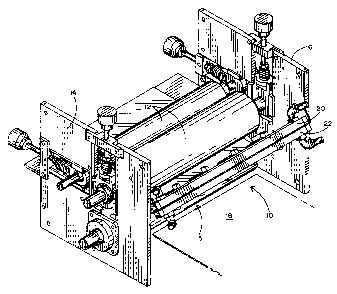
[0008] FIG. 1 is a three-dimensional view of a preferred embodiment of the
present
invention;
[0009] FIG. 2 is a top view of the preferred embodiment;
[0010] FIG. 3 is an elevation view thereof;
[0011] FIG. 4 is a cross-sectional view taken along lines 4-4 of FIG. 3;
[0012 FiG. 5 is a back mechanical layout drawing of the preferred embodiment;
[0013] FIG. 6 is a front mechanical layout drawing thereof; and
[0014] FIG. 7 is a graph of air blast timing of the preferred embodiment.

CA 02488486 2004-11-25
DETAILED DESCRIPTION OF A PREFERRED EMBODIMENT
[0015] Referring to the accompanying figures and specifically to Fits. 1-6, it
will be
seen that a roller coating machine 10 comprises three rollers 12 (including
conventional metering, application and opposed rollers) configured between
structural
members 14 and 16 for coating one side of a thin sheet and depositing it on a
moving
conveyor belt 18.
[0016 The invention herein comprises an air sheet release system 15 which in
the
preferred embodiment utilizes plenums 20 and 22 positioned adjacent the
rollers and
having respective sets of air nozzles 24 and 26 pointed at the edge of each
sheet as
the sheets exit the rollers as seen best in FIG. 4. As will be seen
hereinafter in
conjunction with FIG. 7, the upper nozzles 24 emit a timed pulse of air while
the lower
nozzles 26 emit a constant or steady state air flow to prevent each sheet from
failing to
release from the rollers 12.
[0017] As seen best in FIGs. 5 and 6, (only one plenum is shown for clarity)
each
plenum 20 and 22, terminates at its respective ends in connector elbows 32
which are,
in turn, connected to air hoses 34 joined at a tee 36. The tee 36'is connected
to an air
source through a filter 38, a regulator 40 and a solenoid valve 42. In
addition, each air
nozzle 24, 26 may preferably comprise an adjustment valve 30 to permit
contouring of
the various nozzle air flows to have the desired effect on reliable sheet
release. The
individual nozzles are preferably of the type having a linear array of
apertures so that
the combined air flow is in the form of a sheet of air that runs parallel to
the front edge
of the coated sheet exiting from rollers 12.
6

CA 02488486 2004-11-25
[0018] In the preferred embodiment of the present invention, each of the air
nozzles
24, 26 is a LECHLER Model 600.130. BC plastic pneumatic spray nozzle which has
a
linear array of sixteen one millimeter orifices
(0019] As shown graphically in FIG. 7, in the preferred embodiment of the
present
invention, the lower set of air nozzles 26 emit a constant flow at about 10
psi while the
upper set of nozzles 24 emit a single pulse of air flow at about 20 psi. The
single air
pulse is emitted in response to a sensor positioned relative to rollers 12 to
emit a signal
indicating the imminent travel of a sheet through the rollers. This signal is
transferred
to a monostable multivibrator (not shown) and solenoid valve 42 responds to
the
multivibrator to enable a single air pulse for a selected length of time as
the sheet edge
begins to exit the rollers as shown in FIG. 14. The constant air flow nozzles
26 do not
require a sensor or multivibrator since they need not respond to each
individual sheet.
[0020] Having thus disclosed a preferred embodiment, it will be understood
that
variations are contemplated including for example the number and position of
air
nozzles as well as the air pressures and timing. Accordingly, the scope hereof
is to be
limited only by the appended claims and their equivalents.
[0021] We claim:
7

Representative Drawing
A single figure which represents the drawing illustrating the invention.
Administrative Status

2024-08-01:As part of the Next Generation Patents (NGP) transition, the Canadian Patents Database (CPD) now contains a more detailed Event History, which replicates the Event Log of our new back-office solution.

Please note that "Inactive:" events refers to events no longer in use in our new back-office solution.

For a clearer understanding of the status of the application/patent presented on this page, the site Disclaimer , as well as the definitions for Patent , Event History , Maintenance Fee  and Payment History  should be consulted.

Event History

Description Date
Application Not Reinstated by Deadline 2008-11-25
Time Limit for Reversal Expired 2008-11-25
Deemed Abandoned - Failure to Respond to Maintenance Fee Notice 2007-11-26
Application Published (Open to Public Inspection) 2006-02-09
Inactive: Cover page published 2006-02-08
Inactive: First IPC assigned 2005-02-24
Inactive: IPC assigned 2005-02-24
Filing Requirements Determined Compliant 2005-01-17
Letter Sent 2005-01-17
Inactive: Filing certificate - No RFE (English) 2005-01-17
Application Received - Regular National 2005-01-14
Inactive: Inventor deleted 2005-01-14

Abandonment History

Abandonment Date Reason Reinstatement Date
2007-11-26

Maintenance Fee

The last payment was received on 2006-11-24

Note : If the full payment has not been received on or before the date indicated, a further fee may be required which may be one of the following

  • the reinstatement fee;
  • the late payment fee; or
  • additional fee to reverse deemed expiry.

Please refer to the CIPO Patent Fees web page to see all current fee amounts.

Fee History

Fee Type Anniversary Year Due Date Paid Date
Application fee - standard 2004-11-25
Registration of a document 2004-11-25
MF (application, 2nd anniv.) - standard 02 2006-11-27 2006-11-24
Owners on Record

Note: Records showing the ownership history in alphabetical order.

Current Owners on Record
DORN SPE INCORPORATED
Past Owners on Record
ALFONSO A. MORA
JAMES C. WALKER
Past Owners that do not appear in the "Owners on Record" listing will appear in other documentation within the application.
Documents

To view selected files, please enter reCAPTCHA code :


To view images, click a link in the Document Description column. To download the documents, select one or more checkboxes in the first column and then click the "Download Selected in PDF format (Zip Archive)" or the "Download Selected as Single PDF" button.

List of published and non-published patent-specific documents on the CPD .

If you have any difficulty accessing content, you can call the Client Service Centre at 1-866-997-1936 or send them an e-mail at CIPO Client Service Centre.


Document
Description 
Date
(yyyy-mm-dd) 
Number of pages   Size of Image (KB) 
Abstract 2004-11-25 1 31
Description 2004-11-25 6 188
Claims 2004-11-25 3 75
Drawings 2004-11-25 7 233
Representative drawing 2006-01-12 1 25
Cover Page 2006-01-23 1 60
Courtesy - Certificate of registration (related document(s)) 2005-01-17 1 105
Filing Certificate (English) 2005-01-17 1 158
Reminder of maintenance fee due 2006-07-26 1 110
Courtesy - Abandonment Letter (Maintenance Fee) 2008-01-21 1 175