Language selection

Search

Patent 2488533 Summary

Third-party information liability

Some of the information on this Web page has been provided by external sources. The Government of Canada is not responsible for the accuracy, reliability or currency of the information supplied by external sources. Users wishing to rely upon this information should consult directly with the source of the information. Content provided by external sources is not subject to official languages, privacy and accessibility requirements.

Claims and Abstract availability

Any discrepancies in the text and image of the Claims and Abstract are due to differing posting times. Text of the Claims and Abstract are posted:

  • At the time the application is open to public inspection;
  • At the time of issue of the patent (grant).
(12) Patent Application: (11) CA 2488533
(54) English Title: IMPROVEMENTS IN AUTOMOTIVE POWER STEERING SYSTEMS
(54) French Title: AMELIORATIONS APPORTEES AUX SYSTEMES DE SERVODIRECTION DES VEHICULES AUTOMOBILES
Status: Deemed Abandoned and Beyond the Period of Reinstatement - Pending Response to Notice of Disregarded Communication
Bibliographic Data
(51) International Patent Classification (IPC):
  • B62D 05/06 (2006.01)
  • B62D 07/22 (2006.01)
(72) Inventors :
  • MARSH, ANDREW DAVID (Australia)
(73) Owners :
  • COOPER-STANDARD AUTOMOTIVE (AUSTRALIA) PTY LTD.
(71) Applicants :
  • COOPER-STANDARD AUTOMOTIVE (AUSTRALIA) PTY LTD. (Australia)
(74) Agent: SUSAN M. BEN-OLIELBEN-OLIEL, SUSAN M.
(74) Associate agent:
(45) Issued:
(22) Filed Date: 2004-11-30
(41) Open to Public Inspection: 2006-05-30
Availability of licence: N/A
Dedicated to the Public: N/A
(25) Language of filing: English

Patent Cooperation Treaty (PCT): No

(30) Application Priority Data: None

Abstracts

English Abstract


A device for attenuating shudder in vehicle power steering systems, whereby
a baffle tube is positioned in the power steering hydraulic circuit to break
up
pressure waves which may exist in the system.


Claims

Note: Claims are shown in the official language in which they were submitted.

6
THE CLAIMS DEFINING THE INVENTION ARE AS FOLLOWS:
1. A device for attenuating shudder in vehicle power steering systems, the
device being positioned in the interior of a line or hose of the power
steering
hydraulic circuit to break up pressure waves which may exist in the system.
2. The device for attenuating shudder in vehicle power steering systems of
Claim 1, wherein the device may comprise a baffle positioned in either the
pressure or return hoses.
3. The device for attenuating shudder in vehicle power steering systems of
Claim 2, wherein the baffle may be positioned in the hose or pipe that the
entire fluid flow passes through the baffle, or alternately some of the fluid
may
pass around the outer surface of the baffle.
4. A device for attenuating shudder in vehicle power steering systems as
defined in Claims 2 or 3, the baffle comprising a tube having baffle plates
restricting the fluid flow spaced along the tube to interrupt and reflect
pressure
pulsations.
5. A device for attenuating shudder in vehicle power steering systems as
defined in claim 4 wherein each baffle plate is semicircular, adjacent baffle
plates being oriented 180° from its adjacent baffle.
6. A device for attenuating shudder in vehicle power steering systems as
defined in Claims 1 or 2 wherein the baffle may comprise a spiral wound tuner
cable within a tube, whereby the fluid can pass not only through the tube but
by-pass around the outside of the tube.

7
7. A device for attenuating shudder in vehicle power steering systems
substantially as described in the specification with reference to, and as
illustrated by the accompanying illustrations.

Description

Note: Descriptions are shown in the official language in which they were submitted.


CA 02488533 2004-11-30
2
This invention relates to improvements in automotive power steering systems,
more particularly to modifications to attenuate steering shudder.
Power steering systems are commonly installed in motor vehicles to assist the
driver by reducing the effort required to steer the vehicle while still
retaining a
degree of feel on the steering wheel. The power steering system includes a
hydraulic pump to supply fluid under pressure from a reservoir to a control
valve which directs the oil to either side of a piston rack piston. The rack
is
moved by a pinion on the steering column, the rack piston assisting in the
movement.
The pump delivers high pressure oil to the control valve through a high
pressure line. A low pressure line is connected to the outlet of the control
valve, the low pressure line returns the oil to the reservoir through an oil
cooler
heat exchanger loop.
However a problem exists in many power steering systems. At the time of
sudden steering movements the rapid opening and closing of the control valve
creates large pressure pulses and fluctuations in the hydraulic system. This
creates shudder in the vehicle and can be quite severe to such an extent the
vehicle is un-drivable.
Various attempts have been made to overcome the problem and examples of
these are referred to below.
JP 11321681 describes a system whereby the low pressure oil from the
control valve passes through the oil cooler to the reservoir. An
electromagnetic valve selectively bypasses the oil cooler under the control of
sensors detecting the turning of the wheels in a steering movement.
JP 11115782 provides a hydraulic hose adapted for elastic defom~ation in a
radial direction to absorb pressure variations in a power steering system.

CA 02488533 2004-11-30
3
JP 53002825 discloses a, pair of pistons in a vibration absorbing chamber to
prevent chatter phenomenon at the initial time of steering.
JP 10287256 describes a branch line on the lower pressure line from the
control valve. The branch line is plugged at its end and consists of material
having extensibility to absorb the pressure pulses.
In JP 02274659 the reservoir is divided into two separate chambers. The
pump is fed from one chamber, the return from the control valve exhausts into
the second chamber. From the second chamber the oil passes through an oil
cooler back to the first chamber. The surge pressure from the valve is
1~0 absorbed in the second chamber.
JP 60143181 and JP 60143182 each describe a reaction chamber which
exhibits a damper function to suppress vibration of the valve spool.
US Nos 6119728, 5941283, 5539164, 6338363,4285534 and 4794955
describe various forms of attenuation hoses.
US 4203287 describes an expansible chamber in a power steering system.
US 5193885 describes a power braking system in which pressure pulsations
are absorbed in an accumulator.
!t is an object of the invention to provide a modification to a power steering
system to attenuate steering shudder.
A further object of the invention is to provide a device to attenuate fluid
borne
pulsations that lead to power steering pump noise and shudder.
Thus there is provided according to the invention an attenuating device
positioned in the interior of a line or hose of the power steering circuit to
break
up pressure waves which may exist in the system.

CA 02488533 2004-11-30
4
In a preferred form of the invention, the device may comprise a baffle
positioned in either the pressure or return hoses.
In a preference, the baffle may be positioned in the hose or pipe such that
the
entire fluid flow passes through the baffle, or alternately some of the fluid
may
pass around the outer surface of the baffle.
In a preferred form of the invention, the baffle comprises a tube having
baffle
plates restricting the fluid flow spaced along the tube to interrupt and
reflect
pressure pulsations.
In preference, each baffle plate is semi-circular, adjacent baffle plates
being
I 0 ~ oriented 180 degrees from its adjacent baffle.
In a preferred form of the invention, the baffle mar comprise a spiral wound
tuner cable within a tube, whereby the fluid can pass not only through the
tube, but bypass around the outside of the tube.
In order to more fully describe the invention reference will now be made to
the
I 5 accompanying drawings in which:-
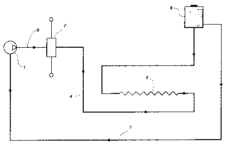
Figure 1 is a diagrammatic sketch of a typical power steering system, and
Figures 2a and 2b are views of one form of the baffle.
Referring to Figure 1 the hydraulic pump 1 delivers pressurised fluid to the
steering control valve 2 through line 3. T.he hydraulic fluid then passes
20 through line 4 including an oil cooler 5 back to the oil reservoir 6
supplying the
pump through line 7.
Figure 2 shows one form of attenuator, in the form of a cylindrical tube 8. In
this embodiment the tube has four baffle plates 9, each baffle plate being
orientated at 180 degrees. Each baffle plate is semi-circular and thus
25 obstructs one half of the interior of the tube. In the embodiment shown
there
are four baffle plates, but it is to be realised other numbers of baffle
plates can

CA 02488533 2004-11-30
be used. In the particular installation in which the baffle was tested four
baffle
plates gave a satisfactory result. If there are more baffle plates, there is
an
increase in back pressure.
The baffle can be positioned in either the pressure line 3 or the return line
4.
5 More specifically the baffle may be mounted as part of a spiral wound tuner
cable arrangement located within the pressure or return hoses.. In this
instance it may be installed such that fluid not only passes through the
baffle
but provides also a fluid path around the outside of the baffle tube.
Aftemately
the baffle can be clamped into the hose allowing fluid to pass only through
the
baffle tube itself.
Thus there has been described an attenuation device in the form of a baffle
tube inserted in the hydraulic circuit of a power steering system, and
although
various forms of the invention have been described the invention is not to be
limited hereto but can include modifications and variations falling within the
spirit and scope of the invention.

Representative Drawing
A single figure which represents the drawing illustrating the invention.
Administrative Status

2024-08-01:As part of the Next Generation Patents (NGP) transition, the Canadian Patents Database (CPD) now contains a more detailed Event History, which replicates the Event Log of our new back-office solution.

Please note that "Inactive:" events refers to events no longer in use in our new back-office solution.

For a clearer understanding of the status of the application/patent presented on this page, the site Disclaimer , as well as the definitions for Patent , Event History , Maintenance Fee  and Payment History  should be consulted.

Event History

Description Date
Inactive: Adhoc Request Documented 2016-11-28
Inactive: Office letter 2016-11-28
Revocation of Agent Request 2016-11-03
Appointment of Agent Request 2016-11-03
Inactive: Dead - No reply to Office letter 2007-03-01
Application Not Reinstated by Deadline 2007-03-01
Application Published (Open to Public Inspection) 2006-05-30
Inactive: Cover page published 2006-05-29
Inactive: Status info is complete as of Log entry date 2006-04-28
Inactive: Abandoned - No reply to Office letter 2006-03-01
Inactive: IPC assigned 2005-03-04
Inactive: First IPC assigned 2005-03-04
Inactive: Courtesy letter - Evidence 2005-01-18
Inactive: Filing certificate - No RFE (English) 2005-01-15
Application Received - Regular National 2005-01-15

Abandonment History

There is no abandonment history.

Maintenance Fee

The last payment was received on 2004-11-30

Note : If the full payment has not been received on or before the date indicated, a further fee may be required which may be one of the following

  • the reinstatement fee;
  • the late payment fee; or
  • additional fee to reverse deemed expiry.

Patent fees are adjusted on the 1st of January every year. The amounts above are the current amounts if received by December 31 of the current year.
Please refer to the CIPO Patent Fees web page to see all current fee amounts.

Fee History

Fee Type Anniversary Year Due Date Paid Date
Registration of a document 2004-11-30
Application fee - standard 2004-11-30
MF (application, 2nd anniv.) - standard 02 2006-11-30 2004-11-30
Owners on Record

Note: Records showing the ownership history in alphabetical order.

Current Owners on Record
COOPER-STANDARD AUTOMOTIVE (AUSTRALIA) PTY LTD.
Past Owners on Record
ANDREW DAVID MARSH
Past Owners that do not appear in the "Owners on Record" listing will appear in other documentation within the application.
Documents

To view selected files, please enter reCAPTCHA code :


To view images, click a link in the Document Description column. To download the documents, select one or more checkboxes in the first column and then click the "Download Selected in PDF format (Zip Archive)" or the "Download Selected as Single PDF" button.

List of published and non-published patent-specific documents on the CPD .

If you have any difficulty accessing content, you can call the Client Service Centre at 1-866-997-1936 or send them an e-mail at CIPO Client Service Centre.


Document
Description 
Date
(yyyy-mm-dd) 
Number of pages   Size of Image (KB) 
Description 2004-11-29 4 151
Abstract 2004-11-29 1 9
Drawings 2004-11-29 2 22
Claims 2004-11-29 2 48
Representative drawing 2006-05-01 1 5
Filing Certificate (English) 2005-01-14 1 158
Request for evidence or missing transfer 2005-11-30 1 100
Courtesy - Abandonment Letter (Office letter) 2006-04-11 1 166
Correspondence 2005-01-14 1 27
Correspondence 2007-07-22 5 157
Correspondence 2007-09-03 3 143
Correspondence 2016-11-02 3 135
Courtesy - Office Letter 2016-11-27 138 5,840