Some of the information on this Web page has been provided by external sources. The Government of Canada is not responsible for the accuracy, reliability or currency of the information supplied by external sources. Users wishing to rely upon this information should consult directly with the source of the information. Content provided by external sources is not subject to official languages, privacy and accessibility requirements.
Any discrepancies in the text and image of the Claims and Abstract are due to differing posting times. Text of the Claims and Abstract are posted:
| (12) Patent: | (11) CA 2488728 |
|---|---|
| (54) English Title: | PROCESS AND ARRANGEMENT FOR WORKING THIN METAL SHEETS AND THIN-WALLED, SINGLE- OR DOUBLE-CURVED PANELS OR SHELLS |
| (54) French Title: | PROCEDE ET MONTAGE DE TRAVAIL DES FEUILLES METALLIQUES MINCES, ET DES PANNEAUX OU DES ENVELOPPES A PAROIS MINCES, A UNE OU A DEUX FACES COURBES |
| Status: | Expired and beyond the Period of Reversal |
| (51) International Patent Classification (IPC): |
|
|---|---|
| (72) Inventors : |
|
| (73) Owners : |
|
| (71) Applicants : |
|
| (74) Agent: | KIRBY EADES GALE BAKER |
| (74) Associate agent: | |
| (45) Issued: | 2009-09-15 |
| (22) Filed Date: | 2004-12-01 |
| (41) Open to Public Inspection: | 2005-06-01 |
| Examination requested: | 2006-09-19 |
| Availability of licence: | N/A |
| Dedicated to the Public: | N/A |
| (25) Language of filing: | English |
| Patent Cooperation Treaty (PCT): | No |
|---|
| (30) Application Priority Data: | ||||||
|---|---|---|---|---|---|---|
|
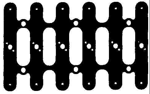
Process for working thin sheet and thin-walled, single- or double-curved, three-dimensionally shaped sheets, panels or shells, by means of material ablation processes, such as milling and drilling, in which in a first step a surface clamping force, sufficient to fix it in position, is generated through a layer acting as distributor or diffuser is generated onto the surface of the work piece to be machined, and in the second step, the machining of the work piece is performed, whereby the cutting parameters, and the cutting speed and feed speed, are so adjusted that a local heating occurs in the zone of contact between tool and work piece, with the temperature peak being greater than or equal to the melting temperature of the surface of the distributor or diffuser, and following the completion of the machining of the work piece, the vacuum clamping is shut off and the work piece is removed from the clamping device.
Procédé pour travailler des feuilles minces, des parois minces et des feuilles, des panneaux ou des enveloppes à simple ou à double courbure ou de forme tridimensionnelle, par des processus d'enlèvement de matière, p. ex. le fraisage et le perçage. D'abord, une force de serrage suffisante pour retenir la pièce est appliquée à une couche agissant comme un distributeur ou un diffuseur et, par conséquent, appliquée à la surface de la pièce à usiner. ensuite, la pièce est usinée, c'est à dire que les paramètres de coupe, la vitesse de coupe et la vitesse de l'alimentation sont réglés pour que la température s'élève dans la zone de contact entre l'outil et la pièce, dont le pic de température est supérieur ou égal au point de fusion de la surface du distributeur ou du diffuseur. Après l'usinage de la pièce, le serrage sous vide est relâché, et la pièce est retirée du dispositif de serrage.
Note: Claims are shown in the official language in which they were submitted.
Note: Descriptions are shown in the official language in which they were submitted.
2024-08-01:As part of the Next Generation Patents (NGP) transition, the Canadian Patents Database (CPD) now contains a more detailed Event History, which replicates the Event Log of our new back-office solution.
Please note that "Inactive:" events refers to events no longer in use in our new back-office solution.
For a clearer understanding of the status of the application/patent presented on this page, the site Disclaimer , as well as the definitions for Patent , Event History , Maintenance Fee and Payment History should be consulted.
| Description | Date |
|---|---|
| Time Limit for Reversal Expired | 2017-12-01 |
| Letter Sent | 2016-12-01 |
| Grant by Issuance | 2009-09-15 |
| Inactive: Cover page published | 2009-09-14 |
| Inactive: Final fee received | 2009-06-16 |
| Pre-grant | 2009-06-16 |
| Notice of Allowance is Issued | 2009-05-12 |
| Letter Sent | 2009-05-12 |
| Notice of Allowance is Issued | 2009-05-12 |
| Inactive: Approved for allowance (AFA) | 2009-05-04 |
| Amendment Received - Voluntary Amendment | 2009-02-03 |
| Inactive: S.30(2) Rules - Examiner requisition | 2008-08-15 |
| Letter Sent | 2006-10-13 |
| All Requirements for Examination Determined Compliant | 2006-09-19 |
| Request for Examination Received | 2006-09-19 |
| Request for Examination Requirements Determined Compliant | 2006-09-19 |
| Application Published (Open to Public Inspection) | 2005-06-01 |
| Inactive: Cover page published | 2005-05-31 |
| Letter Sent | 2005-05-05 |
| Inactive: Adhoc Request Documented | 2005-04-14 |
| Inactive: Single transfer | 2005-03-24 |
| Inactive: Single transfer | 2005-03-24 |
| Inactive: First IPC assigned | 2005-03-02 |
| Inactive: First IPC assigned | 2005-02-25 |
| Inactive: IPC assigned | 2005-02-25 |
| Inactive: Courtesy letter - Evidence | 2005-01-25 |
| Inactive: Filing certificate - No RFE (English) | 2005-01-17 |
| Filing Requirements Determined Compliant | 2005-01-17 |
| Application Received - Regular National | 2005-01-17 |
There is no abandonment history.
The last payment was received on 2009-08-17
Note : If the full payment has not been received on or before the date indicated, a further fee may be required which may be one of the following
Please refer to the CIPO Patent Fees web page to see all current fee amounts.
| Fee Type | Anniversary Year | Due Date | Paid Date |
|---|---|---|---|
| Application fee - standard | 2004-12-01 | ||
| Registration of a document | 2004-12-01 | ||
| Request for examination - standard | 2006-09-19 | ||
| MF (application, 2nd anniv.) - standard | 02 | 2006-12-01 | 2006-11-09 |
| MF (application, 3rd anniv.) - standard | 03 | 2007-12-03 | 2007-08-28 |
| MF (application, 4th anniv.) - standard | 04 | 2008-12-01 | 2008-10-31 |
| Final fee - standard | 2009-06-16 | ||
| MF (application, 5th anniv.) - standard | 05 | 2009-12-01 | 2009-08-17 |
| MF (patent, 6th anniv.) - standard | 2010-12-01 | 2010-08-31 | |
| MF (patent, 7th anniv.) - standard | 2011-12-01 | 2011-09-13 | |
| MF (patent, 8th anniv.) - standard | 2012-12-03 | 2012-10-11 | |
| MF (patent, 9th anniv.) - standard | 2013-12-02 | 2013-09-30 | |
| MF (patent, 10th anniv.) - standard | 2014-12-01 | 2014-09-17 | |
| MF (patent, 11th anniv.) - standard | 2015-12-01 | 2015-10-08 |
Note: Records showing the ownership history in alphabetical order.
| Current Owners on Record |
|---|
| MB-PORTATEC GMBH |
| Past Owners on Record |
|---|
| SIMON METZNER |
| THILO METZNER |

