Note: Descriptions are shown in the official language in which they were submitted.
CA 02488977 2004-12-02
Grinding Arrangement
Field of the Invention
The invention concerns a grinding arrangement with a grinding stone for
grinding at least one knife of a chopper arrangement, a movement arrangement
for
moving the grinding stone along the chopper arrangement, a measurement
arrangement for the provision of a signal that contains information regarding
the
force applied by the grinding stone of the knife during the grinding process
and a
control arrangement that controls the movement arrangement as a function of
the
signal of the measurement arrangement.
Background of the Invention
During the operation of a forage harvester, the knives fastened to the
chopper arrangement wear over time. It is possible that individual knives wear
at
different rates. While the knives around the circumference of the chopper
arrangement as a ruled wear at approximately uniform rates, the wear along the
width of the chopper arrangement may vary considerably. Thereby, the diameter
of
the enveloping circle described by the cutting edges of the knives can vary in
the
axial direction of the shaft of the chopper arrangement. A cylindrical or
slightly
concave shape is desired as a target shape in order to simplify the automatic
repositioning of the shearbar or in order to make this possible depending upon
the
repositioning system. A parallel and precise in-feed of the shearbar towards
the
circumference of the chopper arrangement is indispensable for a effective
chopper
process.
To avoid this problem, US Patent No. 6,503,135 proposes that the actual
shape of the enveloping circle described by the knives of a chopper
arrangement be
detected before a grinding process and to thereupon move the grinding stone on
the
basis of the results of the measurement in such a way that a desired shape of
the
enveloping circle is attained. The shape of the enveloping circle is detected
by
means of a knock sensor or by a magnetic sensor associated with the grinding
stone
or with the shearbar. As an alternative, the force applied to the shearbar is
CA 02488977 2004-12-02
measured.
The disadvantage of a measurement of the spacing between the shearbar
and the knives by means of magnetic sensors, knock sensors or force sensors is
seen I the fact that an additional information about the immediate angle of
rotation of
the chopper arrangement is required in order to be able to associate the
immediate
measurement value of the spacing with the particular knife. Moreover, at high
rotational speeds, the association with the proper knife may be problematic.
In
addition, an improper positioning of the shearbar that is not parallel to the
shaft of the
chopper arrangement may adversely affect the validity of the measurement. If
the
spacing at the grinding stone is detected inductively or by a knock sensor,
there are
problems with the association of the measurement values with an actual
spacing,
since the vibratory pertormance of the grinding stone and the noises generated
by it
are a function of its worn condition. Inductive measurement processes depend
upon
the condition of the knives and are therefore also problematic.
The problem underlying the invention is seen in the need to make available
a grinding arrangement that is improved relative to the state of the art, in
which the
problems cited above do not exist or do so only to a lesser degree.
Summary of the Invention
According to the present invention, there is provided an improved grinding
arrangement for grinding knives of a chopper arrangement.
An object of the invention is to provide a grinding stone arrangement which
has its movement relative to cutting knives controlled by signals representing
the
force applied by the grinding stone to the knives.
The invention proposes that a force measurement cell be attached to any
desired location in the connecting line or power flux connection between the
grinding
stone and the chopper arrangement. The force measurement detects the load or
the
pressure exerted by the grinding stone on the knife or knives of the chopper
arrangement during the grinding process. The value measured by the force
measurement cell is all the greater when the enveloping curve of the knives is
closer
to the grinding stone and the smaller when the knives are separated from the
2
CA 02488977 2004-12-02
grinding stone.
In this way, the result is an absolute and exact measurement value that
contains information about the actual shape of the knife. The chopper
arrangement
can be brought into an optimum shape tat makes possible the repositioning to a
sufficiently small cutting gap. Thereby the energy required for the chopper
operation
can be reduced or at a constant energy level a higher throughput can be
attained.
Furthermore, the quality of the chopper operation or the length of cut is
improved
(that is, the uniformity and precision of the cut). The proportion of uncut
components, such as husks or leaves, is sharply reduced or even eliminated.
The movement arrangement for the grinding stone is controlled by the
control arrangement in such a way that the grinding stone brings the cutting
edge of
the knife into a certain target shape which may be a predetermined shape or a
shape
that can be selected from several inputs or from any desired input shape. In
order to
attain the target shape of the cutting edge of the knife, the control
arrangement can
perform a comparison between the information made available by the measurement
arrangement regarding the actual present shape of the cutting edge and the
target
shape and control the movement arrangement as a function of the result of the
comparison. Thereby, the grinding stone is controlled by the movement
arrangement that transports the grinding stone across the width of the chopper
arrangement and provides an in-feed as a function of the signal of the
measurement
arrangement and brings about a movement of the grinding stone in such a way
that
any deviation in the shape of the cutting edges of the knives is automatically
equalized.
The chopper arrangement may include a chopper drum in open or closed
form to which several knives are attached. The chopper drum is arranged on a
shaft
that is brought into rotation during the grinding and in its normal operation,
as a rule,
rotates in the opposite direction compared to the normal chopper operation. In
the
case of chopper drums of this type, the measurement arrangement detects
information about the distance between the shaft and the cutting edges of the
knives,
that is, the radius of the enveloping circle described by the cutting edges.
However,
the invention can also be applied to chopper arrangements with web disk wheel
3
CA 02488977 2004-12-02
choppers. There it is not the radius of the cutting edges of the knives that
is
detected, but their axial position.
The force measurement cell can be attached between the grinding stone
retainer of the grinding stone and a frame to which the grinding stone
retainer is
fastened and that also carries the chopper arrangement. As a rule, the
grinding
stone retainer can be traversed across the width of the chopper arrangement
and is
supported in bearings on a shaft. The force measurement cell may be arranged
between the shaft and the frame or between the shaft and the grinding stone
retainer.
Alternatively, or in addition, there is the possibility of arranging the force
measurement cell between the grinding stone and the grinding stone retainer.
Furthermore, the control arrangement can make an error signal available in
case the measured force that is applied to the grinding stone exceeds a
threshold
value. This error signal can be provided to the operator optically or
acoustically and
points to a knife projecting too far outward. Moreover, in this case the
grinding
process can be stopped automatically. Thereby, damage (breaking out) or
unusual
wear of the grinding stone can be avoided, since in the case of excessive
force
between the grinding stone and the drum countermeasures are taken.
The present invention can be applied to a multitude of arrangements with
knives that must be sharpened. It can be used in particular on self propelled
or
towed harvesting machines with chopper drums or web disk wheel choppers.
Brief Descrption of the Drawings
The drawings show two embodiments of the invention that shall be
described in greater detail in the following.
Fig. 1 is a schematic left side view of a harvesting machine with a chopper
arrangement.
Fig. 2 is a front view of a first embodiment of a grinding arrangement.
Fig 3 is a front view of a second embodiment of a grinding arrangement.
Description of the Preferred Embodiment
4
CA 02488977 2004-12-02
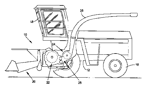
The harvesting machine 10 shown in FIG. 1 in the form of a self-propelled
forage harvester is supported on a frame 12 that is carried by front and rear
wheels
14 and 16. The harvesting machine 10 is controlled from an operator's cab 18
from
which a harvested crop take-up arrangement 20 can be seen. Crop taken up from
the ground by means of the take-up arrangement 20 can be seen. Crop taken up
from the ground by means of the take-up arrangement 20, for example, corn,
grass
or the like, is conducted to a chopper arrangement 22 in the form of a chopper
drum,
which chops it into small pieces and delivers it to a conveyor arrangement 24.
The
crop leaves the harvesting machine 10 to an accompanying trailer over a
discharge
duct 25 mounted for being selectively rotated about an upright axis. A post-
chopper
reduction arrangement 28 extends (during the corn harvest) between the chopper
arrangement 22 and the conveyor arrangement 24 through which the crop to be
conveyed is conducted tangentially to the conveyor arrangement 24.
Fig. 2 shows a schematic view of a chopper arrangement 22 and a grinding
arrangement 26 associated with it, as it is seen when looking at the
harvesting
machine 10 in Fig. 1 from the front (relative to the direction of operation).
The
chopper arrangement 22 is provided with a number of knives 38 distributed over
its
width at its circumference which cut harvested crop taken up by the harvested
crop
take-up arrangement 20 in interaction with a rigid shearbar 46. The chopper
arrangement 22 includes a central shaft 32, that can be driven in rotation by
means
of a belt pulley 36 at its end face and belts, not shown, by a motor of the
harvesting
machine 10. The shaft 32 is supported by two rolling contact bearings 56
arranged
on both sides of the chopper arrangement 22 on the frame 12 of the harvesting
machine 10.
In order to be able to sharpen the knives 38 after a certain operating time,
without having to disassemble the individual knives 38 or the entire chopper
arrangement 22, the grinding arrangement 26 is provided above the chopper
arrangement 22 near the enveloping circle described by the knives 38. The
grinding
arrangement 26 essentially includes a grinding stone 42, a grinding stone
retainer 40
associated with it and a support shaft 44 oriented parallel to the shaft 32,
on which
the grinding retainer 40 is supported in bearings, free to slide.
CA 02488977 2004-12-02
If the knives 38 are to be sharpened, the chopper arrangement 22 is brought
into rotation, as a rule in the opposite direction of rotation andlor at a
reduced
rotational speed, compared to the normal chopper operation. The grinding stone
retainer 40 with the grinding stone 42 attached to it is shifted across the
entire width
of the chopper arrangement 22 by means of a movement arrangement 48 from a
rest or park position, not shown, in which it is arranged at the side
alongside the
chopper arrangement 22. Thereby, the underside of the grinding stone 42 is in
contact with the knives 38 and sharpens them. During the grinding process, the
grinding stone 42 traverses several times across the width of the chopper
arrangement 22. The end points of this sliding movement are illustrated in
Fig. 2 by
the grinding stone retainers with the part number call-out 40 at the left
reversal point
and 40' at the right reversal point.
Between the sliding traverse movements, an in-feed of the grinding stone 42
can be performed, that is a small movement of the grinding stone 42 towards
the
knives 38. In the embodiment shown for this purpose, a mechanical element
(ratchet wheel) is used that interacts with an element fixed to the frame when
one or
both of the reversal points of the grinding stone retainer 40 are reached. The
rotation of the mechanical element is converted into a sliding movement by
means of
a screw thread, so that the grinding stone 42 is provided with an in-feed
towards the
chopper arrangement 22. When the grinding stone 42 is shifted only over a
limited
sideways shift region, an in-feed movement can be avoided, since then the
mechanical element does not come into contact with the stationary element. A
grinding of this type without in-feed is appropriate for the honing at the end
of the
grinding process.
The movement arrangement 48 of the grinding arrangement 26 is controlled
by a control arrangement 52, shown schematically in Fig. 2 which controls the
shifting of the grinding stone 42 by the movement arrangement 48 as well as
the in-
feed in the manner described above. The control arrangement 52 is supplied
with
information about the immediate position of the grinding stone 42, this can be
provided by a corresponding sensor 58, which detects the immediate position of
the
movement arrangement 48, or that the control arrangement 52 has been supplied
6
CA 02488977 2004-12-02
with information into which position it has brought the grinding stone
retainer 40. For
this purpose, for example, the number of impulses can be stored in memory that
have been delivered to a stepper motor of the movement arrangement 48. In
addition, the control arrangement 52 can control the drive of the chopper
arrangement 22.
It should be noted that the in-feed could also be performed by a separate
motor, particularly an electric motor or a hydraulic motor, that would also
have to be
connected with the control arrangement 52. In place of an in-feed by moving
the
grinding stone 42, the entire grinding stone retainer 40 or the shaft 44 could
be
moved in the in-feed direction.
The control arrangement 52 is connected with a memory 54 and with two
force measurement cells 50, that are used as a measurement arrangement. The
force measurement cells 50 are arranged close to both ends of the shaft 44
between
the shaft 44 and the frame 12 or an element connected to it. The force
measurement cells 50 may be of any desired configuration, such as piezo-
electric
sensors or strain gages. They deliver a measurement value to the control
arrangement 52, that is proportional to the force applied to the knives 38 by
the
grinding stone 42 or the reverse. this force contains information regarding
the
enveloping curve described by the knives 38 on the immediate position of the
grinding stone 42. If the grinding stone retainer 40 is supported on two
parallel
shafts 44, each of the shafts 44 can be associated with two force measurement
cells
50 at the ends, or the two shafts 44 are connected to each other at both ends
and
supported in each case on the frame over a single force measurement cell 50.
The
use of a single shaft 44 is also conceivable that has a non-circular cross
section (for
example, a rectangular cross section).
A grinding process can take place as described in the aforementioned U.S.
Patent No. 6,503,135. After the beginning of the grinding process, the control
arrangement 52 brings about a traverse across the width of the chopper
arrangement 22 by the grinding stone 42 by means of the movement arrangement
48, and then is again traversed back into the original position. Thereby, the
grinding
stone 42 can remain in the position into which it was brought during the
preceding
7
CA 02488977 2004-12-02
grinding process, or, if necessary, provided with an in-feed towards the
chopper
arrangement 22. This process can be used to determine whether an in-feed of
the
grinding stone 42 is required. This is the case if no signal (or a relatively
minor
signal) is generated by the force measurement cell 50 in at least one location
of the
chopper arrangement 22. In this case, there is an indentation, recess or the
like in
the knives 38, that cannot be removed or equalized without an in-feed. This
process
can also be omitted, particularly if a control is performed subsequently to
determine
whether the grinding process was successful.
During the traverse of the width of the chopper arrangement 22, the force
measurement cell 50 generates a signal that is a function of the spacing
between the
cutting edges of the knives 38 and the grinding stone 42. The control
arrangement
52 is supplied with information over an appropriate analog digital converter
about the
amplitude of this signal.
At first, the grinding stone 42 is not in-fed any further and is brought to a
first
position at the chopper arrangement 22, as a rule at the left or right
outside. It
remains in this position until the force measurement cell 50 generates an
output
signal that corresponds to a desired force between the grinding stone 42 and
the
cutting edges of the knives 38, so that a sufficient sharpness is attained by
the parts
of the knives 38 that interact with the grinding stone 42. After that, the
grinding stone
42 is transported by the movement arrangement 48 through a distance
corresponding to its width further to the left or the right and grinds the
knives there.
In this way, the entire width of the chopper arrangement 22 is processed
successively. As a rule, the process described is repeated and/or performed
multiple times at a reversed direction of movement. At the conclusion of the
grinding
process, a normal grinding and/or honing of the entire chopper arrangement 22
can
be performed in a manner known in itself. Finally, the grinding stone 42 is
brought
into its park position.
A grinding process alternative to that described above is performed in such
a way that the grinding stone 42 continuously traverses the entire width of
the
chopper arrangement 22, until a constant spacing between the shaft 32 and the
cutting edges of the knives 38 is attained. The control arrangement 52 can
8
CA 02488977 2004-12-02
recognize from the output signal of the force measurement cell 50, whether a
constant spacing between the shaft 32 and the cutting edges of the knives 38
has
been reached, and that corresponding thereto the grinding process can be
ended. In
this move, and in-feed of the grinding stone 42 can be performed, if the force
measurement cell 50 does not detect a contact between the grinding stone 42
and
the knives 38 at one or more places of the chopper arrangement 22.
To control the success of the operation or since the grinding stone 42 wears
down during the grinding, which can result in an unsatisfactory result of the
grinding
process, the control arrangement can traverse the grinding stone retainer 40
one
more time before the honing or during a subsequent normal grinding process
across
the width of the chopper arrangement 22 and detect the space in between the
shaft
32 and the cutting edges of the knives 38 by means of the force measurement
cell
50. If the shape of the cutting edges of the knives 38 is unsatisfactory here,
a new
grinding process is performed in the manner described above.
Fig. 3 shows a second embodiment of a grinding arrangement 26 according
to the invention. Components that correspond to those of the first embodiment
are
designated by the same part number call-outs. There is a difference regarding
the
force measurement cell 50 that is arranged between the grinding stone 42 and
the
grinding stone retainer 40 in the embodiment according to Fig. 3. Here the
force
measurement cell 50 also delivers information regarding the force applied by
the
grinding stone 42 to the knives 38. The control arrangement 52 controls the
movement arrangement 48 as a function of this information in the manner
described
above. The electrical connection between the force measurement cell 50 and the
control arrangement 52 can be performed by a flexible cable or by a contact
strip
located on the shaft 44 connected with the control arrangement 52, which is
fixed to
the frame and electrically insulated from the shaft 44, with which a second
contact
strip on the grinding stone retainer 40 interacts, this is connected with the
force
measurement cell 50. Alternatively, a radio frequency connection is provided
between the force measurement cell 50 and the control arrangement 52.
Having described the preferred embodiment, it will become apparent that
various modifications can be made without departing from the scope of the
invention
9
as defined in the accompanying claims.