Note: Descriptions are shown in the official language in which they were submitted.
CA 02489023 2008-09-04
-1-
SYSTEM AND METHOD FOR BREAST LIFTING
FIELD OF THE INVENTION
The present invention is generally in the field of breast shape correction
and more specifically it is concerned with breast lifting.
The system according to the present invention may be applied only for the
purpose of breast lifting, where the shape of a female's breast is altered or
revised, without carrying out a surgery, i. e. only effecting the actual shape
of the
breasts, without removing breast tissue and without augmentation (adding
implants of any type). However, the system may also be applied in conjunction
io with breast augmentation or breast size reduction, which are surgical
procedures.
BACKGROUND OF THE INVENTION
Over the years, factors such as pregnancy, nursing, and the force of
gravity take their toll on a woman's breasts. This situation is known as
ptosis and
is defined as a situation at which the nipple-areola complex projection is
lower
is then the infra-mammary fold, i. e. the nipple is below the level of the
lower
breast crease.
As the skin loses its elasticity, the breasts often lose their shape and
firmness and begin to sag, obtaining a teardrop like shape rather then a cone-
like
shape.
20 Breast lifting, also referred to by the alternative names mastopexy and
manzmoplasty, is a procedure used for reshaping saggy and loose breasts,
elevating the nipple and areola to a higher level and, thus affording the
breast its
former shape and firmness which can result in a revitalized body image that
can
bolster a woman's self-esteem.
25 Many women use a push-up bra to support their breasts. This however is
at times uncomfortable and may be restricting as far as the selection of
clothing.
CA 02489023 2008-09-04
-2-
Mastopexy procedure according to prior art techniques involves reducing
ptosis (sagging of the breast caused by stretched skin, in many cases due to a
great loss of breast tissue). During a breast lift, long incisions are made
along the
natural creases in the breast and around the dark skin surrounding the nipple
(areola), a keyhole-shaped incision above the areola is also made to define
the
new location for the nipple. Excess skin is removed from the lower section of
the
breast and the areola, nipple, and underlying breast tissue are repositioned
up to a
higher position.
The nipple is moved and incisions are closed with sutures.
Several methods for performing a mastopexy are known, and the
technique opted for depends mainly on the amount of breast and fat tissue, the
amount of skin to be removed, symmetry in volume of breasts and size of
areolas, and choice and taste of patient. Since the procedure involves
surgery, it
may be coupled with breast augmentation and with resizing or repositioning of
the areola to a more aesthetically pleasing position and the shape of the
mound
may be improved by placement of breast implants. Occasionally, only a one-
sided breast lift is required, when the other breast is in a reasonable
position on
the chest and does not require a breast lift.
U. S. Patent No. 5,676, 161 to Breiner discloses a mastopexy procedure
according to which an anchor-shaped incision is made, having a bottom line
along the infra-mammary crease, using a circular cutter to form the top
portion of
the incision and an incision around the areola to reduce the diameter thereof.
After removing excess skin inside the incision, and breast tissue in the case
of
mammaplasty, shifting the areola, nipple and underlying breast tissue upward
to
position the areola/nipple complex within the circular top portion, pulling
the
flaps of skin formed to the sides of the incision down and around the areola
and
underneath same, and then suturing adjacent skin edges to complete the lifting
and reshaping.
U. S. Patent No. 5,584, 884 to Pignataro discloses a mammary prosthesis
comprising a wedge shaped sheet of flexible biocompatible material having
CA 02489023 2008-09-04
-3-
reinforced upper and lower attachment portions for attachment to bone of a
patient
by bone anchors, with the lower attachment portion being anchored to one
or more ribs. The lower attachment portion includes a support member less
flexible than the sheet material having suture receiving openings for
receiving
bone anchor sutures.
U. S. Patent No. 5,217, 494 to Coggins et al discloses a prosthesis for
supporting tissue which among others may be used also in a breast lift
procedure,
wherein one end of the prosthesis is implanted deep into the breast tissue and
the
io opposed end is attached to either the clavicle or the rib.
These procedures are typically performed under general anesthesia,
though at times local anesthesia is sufficient, and they may last several
hours,
depending on the extent of the surgery.
As with any surgery, there is always a possibility of complications such as
a reaction to the anesthesia, bleeding and infection (which may cause scars to
widen).
Mastopexy does leave noticeable, permanent scars, although are so
planned as to be concealed by a woman's bra or bathing suit. One may expect
that after about one year the scars will hardly be noticeable. As far as
aesthetics,
there may also be some dissatisfaction, as the final appearance may not always
meet the patient's expectations. Furthermore, a breast lift performed
according to
conventional techniques won't keep firm forever, the effects of gravity,
pregnancy, aging, and weight fluctuations will eventually take their toll
again.
It is an aspect of the present invention to provide a novel system and a
method for breast lifting, wherein the above drawbacks are significantly
reduced
or overcome. The system according to the invention and the method for carrying
it out are minimally invasive and may be considered as non-surgical, i. e.
they do
not involve incisions (but rather two or four stab incisions) and removal of
excess
skin, nor do they require stitches. However, the system may also be used in
CA 02489023 2010-08-12
-4-
conjunction with breast enlargement (breast augmentation with mastopexy) or
breast size reduction, which are surgical procedures.
SUMMARY OF THE INVENTION
The present invention provides a system for breast lifting, wherein one or
more anchors are fixed to a posture tissue, above the desired nipple level
with
one or more suspending members cradling the breast and extending from the one
or more anchors, such that tensioning the suspending members entails lifting
of
the breast.
The posture tissue is preferably a bone (ribs or collar bone), though it may
i o also be a muscle tissue (pectoral or intercostals). For each breast,
anchors may be
fixed to one or more posture, depending on the physiology/anatomy of the
patient, the shape of the breast prior to lifting, and the desired lifting
result. An
anchor may be a bolt fixture or a threaded fixture typically, but not
restricted
thereto, a self tapping screw) for screw-fixation into a bone, a suspending
hook
for bearing from a bone, i. e. clinging from the bone, or a clasp formed with
hooks for grasping soft tissue (muscle). Alternatively, where the posture
tissue is
a muscle, the suspension member may be fixed thereto by stitching. According
to
still an alternative, the suspension member may be attached to a bone by tying
or
yarning it through a bore formed through the bone.
A suspension member according to the invention may be a tendon-like
wire or a mesh, made of organic material (e, g. tendons), or synthetic
material (e.
TM
g. silicone, Gortex, etc. ).
According to a preferred embodiment of the invention, the suspension
member is formed with or comprises a cradling portion or a cradling member
respectively, having increased surface area than the suspension member, for
supporting the breast from below and padding it, said cradle being a mesh, a
strap or a tube-like member mounted on a wire-like suspension member.
A significant advantage of the present invention, apart from the fact that it
is a so called minimal invasive procedure, is that the aesthetic results and
CA 02489023 2008-09-04
-5-
appearance may be modified to match with customer's expectations during, or
any time after the procedure, i. e. corrections may be easily effected after a
while
(typically several years), if ptosis reoccurs.
The proposed procedure approves well with other medical procedures and
may be combined with breast enlargement (augmentation) or breast reduction.
Even more so, the procedure is completely reversible. Apart from that the
procedure is fast and relatively inexpensive, and the patient is dismissed
shortly
after, leaving practically no scars.
The procedure according to the present invention is carried out by
io inserting a tool through one or two locations at a bottom face of the
breast,
directed towards the posture tissue such that it passes through the breast
tissue.
The tool is used for fixing the anchor to the posture, and according to an
embodiment thereof, the tool is also used for guiding and manipulating the
suspension member so as to cradle the breast and then tensioning the
suspension
member at the required extent.
In some cases, depending among others on breast size, two sets of such
system may be required for a breast, so as to improve the under support.
According to a further aspect of the present invention there is provided a
method for breast lift, said method comprises the following steps: a)
introducing
through the breast at least one anchor and fixing it to a posture tissue; b)
yarning
a suspension member through the breast; said suspension member extending
from said at least one anchor and passing within fat tissue at a bottom
portion of
the breast so as to cradle the breast; c) tensioning the suspension member to
thereby lift the breast; and d) fixating the length of the suspension member.
An alternative method comprises the following steps: a) yarning a
cradling member of a suspension member through the breast, at a bottom
thereof,
such that loose ends thereof extend from the breast; b) fixing at least one
anchor
to a posture tissue, at a level above the desired nipple level; c) attaching a
suspension member to the at least one anchor; d) articulating the loose ends
of
CA 02489023 2008-09-04
-6-
the cradling member to the suspension member and fixedly adjusting the length
thereof.
According to a preferred embodiment, two anchors are fixed to the posture
tissue, with a suspension member extending from each one, such that the loose
ends of the cradling member are articulated to each respective end of a
suspension member. Still preferably, excessive ends of the suspension members
and of the cradling member, are trimmed.
The method according to an embodiment thereof further comprises fitting
a cradle member on the suspension member, for supporting the breast from
to below.
According to one application, the cradle member is a strap-like portion
(possibly a mesh-like material) continuously extending from the suspension
member.
According to a different application, the cradle member is integral with or
mounted over a supplementary member fixedly attached to the suspension
member, whereby the breast height is set by adjusting the relative length of
the
suspension member and the supplementary member.
Where the system is used in conjunction with a breast enlarging
procedure, the cradling portion may directly support the implant.
The present invention has several significant advantages, namely: a) the
mere incisions are two or four stab incision, which are fast healing and
practically leave no scars; b) the procedure is considerably shorter than any
prior
art procedure; c) the procedure may be carried out under local anesthesia,
whereby the patient may be dismissed shortly after; d) the procedure is
adjustable
and reversible at any time; e) the procedure is considerably cheaper then any
prior art procedure; and f) the procedure does not affect sensitivity of the
breast
or nipple and it does not have any consequences concerning breast feeding.
For carrying out the procedure of the present invention, there is provided a
tool kit, which depending on the specific procedure, will include one or more
of
CA 02489023 2008-09-04
-7-
the following tools: a) tool for stabbing the breast and yarning a cradling
member
there through, such that its free ends extend from the breast; the same tool
may be used for creating a passage through the breast for the suspension
member ; b) tool for deploying and fixing the anchors to a posture tissue
(bolting
or screwing in the case of a bone posture; stitching in the case of muscle
tissue);
this tool is also used for yarning the suspension member which is articulated
to
the anchor; c) tool for articulating and tensioning ends of the cradling
member to
the suspension members, and for adjusting the length, fixating and trimming
excessive ends.
However, according to different applications, rather than using a tool, the
slack end of the cradling member and the corresponding slack end of the
suspension member, may be manually tensioned and tied to one another, their
ends being trimmed by conventional means.
The present invention further calls for a tool useful in carrying out a
procedure according to the invention, said tool adapted for tensioning and
clamping cord-like slack ends of the cradling member and a corresponding
suspension member; said tool comprising a housing fitted at a fore end with a
cord receiving opening for receiving two or more cords, a clamp deploying
mechanism for clampingly articulating the at least two cords, and a cord
trimming mechanism for trimming the cords adjacent the clamp.
According to another aspect of the present invention, there is provided a
kit for performing a breast-lift procedure, the kit comprising at least one
set of
suspension members, anchoring means for anchoring a suspension member to a
posture tissue, and means for tensioning and fixating the suspension member.
The kit may also comprise one or more breast-cradling/padding members and
one or more tools, e. g. a tool to facilitate tensioning clamping and trimming
of a
suspension member and a cradling member.
CA 02489023 2008-09-04
-8-
BRIEF DESCRIPTION OF THE DRAWINGS
In order to understand the invention and to see how it may be carried out
in practice, some embodiments will now be described, by way of non-limiting
examples only, with reference to the accompanying drawings, in which:
Fig. 1 is a partially sectioned side view illustrating the anatomy of an
erect, firm breast;
Figs. 2 is a side view illustrating a saggy breast;
Figs. 3A to 3H are consecutive steps of carrying out a breast lift procedure
according to a first embodiment of the present invention;
Figs. 4A to 4G are consecutive steps of carrying out a breast lift procedure
according to a second embodiment of the present invention;
Fig. 5A is a side section through a saggy breast prior to breast lift;
Fig. 5B is a side section through the breast in Fig. 5A, after breast lift;
Fig. 6 is a front view of a female body, superimposing how the breasts are
is supported by two suspension members;
Figs. 7A to 7C are schematic side views illustrating different
embodiments of anchoring means; and
Figs. 8A to 8D illustrate a surgical tool useful in carrying out a breast-
lifting procedure, in four consecutive operative positions.
DETAILED DESCRIPTION OF EMBODIMENTS
The breast 10 seen in Fig. 1 is firm and erect though of small size. One
can notice that the nipple 12 is facing forward and that the nipple-areola
complex
projection is higher than the infra-mammary fold 16, i. e. the nipple 12 is
well
above the level of the lower breast crease 16. Contrary thereto, the breast 20
of
Fig. 2 is saggy and it is noticed that the nipple 22 is facing downward and
extends below the infra-mammary fold 24.
Reverting to Fig. 1, one can further notice several ribs 26, pectoral muscle
28, intercostals muscles 30 and the fat tissue 34.
CA 02489023 2008-09-04
-9-
Turning now to Figs. 3A to 3H, there is illustrated a sequence of carrying
out a breast lift according to a first embodiment of the present invention.
At a first step, after locally anesthesia of the beast 40, two stab incisions
42 are formed at a bottom portion of the breast, with a surgical tool 44 (Fig.
3A).
Then using another tool 45, a passage 46 is formed between the incisions and
using that tool, a cradling member 48 is yarned through the passage 46, such
that
its slack ends 52 extend through the incisions 42 (Fig. 3B). As seen in Fig.
3B,
the cradling member 48 comprises a central band-like portion 56 adapted for
cradling and supporting the breast from below, and two yarns 52 extending at
i o each side thereof.
The band-like portion 56 as well as the yarns 52 may be made of organic
material, e. g. tendons, or synthetic material e. g. Gortex, etc.
Using tool 45, two passages 58 are made (Fig. 3C), preferably extending
from the incisions 42. It is however noticed that the passages 58 may be
formed
before inserting the cradling member 48. Through the passages 58 an anchoring
tool 64 is applied (Fig. 3D), said tool 64 being pre-fitted with an anchoring
screw
68 (preferably a self tapping screw) and a suspension member in the form of a
cord 70 attached to the anchor screw 68. By means of tool 64 the anchor screw
68 is screwed to rib 72. The same procedure takes place through both passages
58, with slack ends 76 of the suspension members extending from the incisions
42.
Using a different tool designated 80 (such a tool is disclosed in more
detail with reference to Figs. 8A to 8D), slack end 52 of the cradling member
and
the corresponding slack end 76 of the suspension member, are articulated,
simultaneously at both sides of the breast (Fig. 3E). Preferably while the
patient
is in an upright position, tensioning begins using the tool 80, by repeatingly
pulling trigger 84, until the breast elevates to a desired position. This
action
provides real time indication of the breast's new form and position, and even
more so, the patient may take part in deciding to what extent to lift the
breasts.
CA 02489023 2008-09-04
-10-
Once the breast 40 assumes the desired repositioning and form, a fixing
clamp 88 is applied by tool 80 (Fig. 3G), and by further manipulating trigger
84
of
the tool 80, the slack ends 52 of the cradling member and the
corresponding slack ends 76 of the suspension member are trimmed (Fig. 3H).
The tool is then removed and shortly after the patient may be dismissed,
with complete healing expected in a mater of days, essentially not leaving any
noticeable scars.
According to a different application, rather than using a tool, the slack end
io 52 of the cradling member and the corresponding slack end 76 of the
suspension
member may be manually tensioned and tied to one another, their ends being
trimmed by conventional means, as known in the art of suturing.
Further attention is now directed to Figs. 4A to 4Q illustrating still
another method for carrying out a breast lift according to the present
invention.
First, two stab incisions 94 and 96 are made at a bottom portion of the
breast 98, and a corresponding passage 100 and 102 is formed extending towards
a suitable posture tissue, rib 104 in the present example (Fig. 4A). A
transverse
passage 109 is formed between the incisions 94 and 96. Then a tool 108,
resembling a screwdriver, is introduced through the first passage 100, said
tool
carrying at its fore end an anchor in the form of screw 110, to which a
suspension
cord 112 is attached. The anchor is fixed to the rib 104 (Fig. 4B), and the
tool
108 is removed leaving a long free end 114 of the suspension member, extending
from the incision 94 (Fig. 4C). Preferably, tool 108 is fitted with a screw
holding
member (not shown), to prevent the screw 110 from departing from the tip of
the
tool.
The free end 114 is then yarned back through the incision 94, through the
transverse passage 109 and out through the second incision 96, leaving a
looped
portion 120 extending from the first incision 94 (Fig. 4D). A second anchor
124
is then provided, which comprises an eye for slidingly receiving the
suspension
cord 112, and a clamp 128 is loosely mounted over two overlapping portions of
CA 02489023 2008-09-04
-11-
the suspension cord (Fig. 4D). Using the same tool 108 (not shown in Fig. 4D),
the second anchor 124 is introduced through the second passage 102 and is then
attached to the rib 104, whilst the loose end 130 of the suspension cord
extends from incision 96 (Fig. 4E).
The loose end 130 is then pulled in direction of arrow 134 (Fig. 4F),
shrinking the looped portion 120 and tensioning the suspension cord until the
breast is deformed and lifted to a desired extent. At this point, a clamping
tool
136 is introduced through incision 96, to shrink the clamp 128, so as to
thereby
fixate the tension of the suspension cord.
As mentioned in connection with the embodiment of Fig. 3, the tensioning
step (Fig. 4F) is preferably carried out while the patient is in an upright
position,
such that actual indication is available regarding the breast's new form and
position, and even more so, the patient may take part in deciding to what
extent
to lift the breasts.
The loose end 130 is then trimmed, possibly by tool 136 (Fig. 4G) and the
procedure is complete. Shortly after the patient may be dismissed, with
complete
healing expected in a mater of days, essentially not leaving any noticeable
scars.
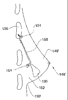
Turning now to Figs. 5A and 5B, there is illustrated a breast 146 which in
Fig. 5A is prior to beast lift and it is noticeable that nipple-areola complex
148
projection is lower then the infra-mammary fold 150. However, in Fig. 5B the
same breast, now designated 146' has undergone a breast lift procedure in
accordance with the present invention and in this Figure the nipple-areola
complex 148' projection is higher then the infra-mammary fold 150'. Further
noted in Fig. 5A, a screw type anchor 154 is screw fixed into a rib 156, with
a
suspension member in the form of cord 158 being attached thereto. A cradling
member 160 extends through the fat tissue 162 of the breast, supports the
breast
from below, said cradling member being tensioned and articulated to the
suspension member by clamp 164, thus lifting the breast and imparting it a
firm
and erect appearance.
CA 02489023 2008-09-04
-12-
In Fig. 6, a female's thorax 170 is seen in which both the left and right
breast 172 and 174 respectively, are supported by two sets of breast-lifting
systems (176 and 178 for the right breast; and 180 and 182 for the left
breast),
each breast-lifting system being substantially similar to the systems
disclosed
herein
above. The difference resides in that each breast is supported by two sets
and it is noticed that whilst in the left breast 172 each suspension member is
anchored by two distinct anchors (186; 188 for breast-lifting system 176, and
190; 192 for breast-lifting system 178), in the right breast 174 each
suspension
io member is anchored by only one, common anchor (196 for breast-lifting
system
180, and 198 for breast-lifting system 182).
Figs. 7A to 7C illustrate 3 breasts, each lifted by a breast lifting system
according to the invention, each fitted with a different anchoring means for
attaching the suspension member to a posture tissue. In the breast 199 of Fig.
7A,
the anchor is a threaded anchor 200 screw-coupled into a rib 202, with a
suspension member 204 attached to the anchor. It is appreciated that the screw-
type anchor may be a self-screwing thread type i. e. does not require
preparatory
boring in the bone tissue, there may be a bolt-type anchor, i. e. of the type
which
is inserted into a bore pre-drilled in the rib.
The breast 212 in Fig. 7B is supported by a system in which a brace-type
anchor 216 which is attached to two neighboring ribs 218 and 220, e. g. by
screws etc. in Fig. 7C the breast 224 is supported by a system according to
the
invention in which the anchor is a suspending hook 228 bearing (clinging) from
rib 230.
However, as mentioned herein above, the anchoring member may also be
attached to muscles e. g. by stitching or by a clasp, etc.
The cradling member 231 illustrated in the Figs. 7A to 7C may be, for
example, a tube-like member mounted on the suspension member 204, for
increasing the sectional area thereof.
CA 02489023 2008-09-04
- 13-
According to another aspect of the invention, there is provided a surgical
tool useful in carrying out the method disclosed with reference to Figs. 3A to
3H.
A tool 250 is illustrated in more detail with further reference to Figs. 8A to
8D.
The tool 250 has a general pistol-like shape having a gripping portion 252
fitted with a clamping trigger 256, and a stem portion 258 having a fore end
260.
At least the fore end is sized for inserting through a stab-incision formed
in a breast, as illustrated for example in Figs. 3E to 3G. The fore end 260 is
fitted
with a clamping unit receptacle 264 (best seen in Fig. 8D), accommodating an
annular locking member 266 having a serrated inner bore 267 sized to receive
1 o therethrough an end of the cradling member 52 and a corresponding end of
the
suspension member 76 (see Fig. 3E). The stem portion 258 comprises a central
bore 268 accommodating an elongate plug-stem 270 extending from the
clamping unit receptacle 264 towards a rear end 272 of the stem portion, where
it
projects and is articulated to a lever 276 of the trigger 256. A plug 278 is
integrally connected by a tear zone 279 to a fore end of the plug-stem 270.
The
plug 278 is serrated and sized for snapingly locking within the locking member
266.
Coaxially received within the central bore 268 there is a trimmer 280
having a trimming end 282 at a fore end and a pusher 286 at its rear end, said
pusher comprising two bores 287. Two bores 288 and 290 extend through a
portion of the stem portion 258, fitted for receiving the end of the cradling
member 52 and a corresponding end of the suspension member 76.
In use, the end of the cradling member 52 and the suspension member 76
are threaded through the locking member 266, yarned through the bores 288 and
290 respectively, then extending through the rear end 274 and through the
bores
287 (Fig. 8A). This step is carried out at a step corresponding with the step
illustrated in Fig. 3E. Then, the ends of the cradling member 52 and of the
suspension member 76 are manually tensioned (Fig. 8A) to the desired position
of the breast.
CA 02489023 2008-09-04
-14-
Upon squeezing trigger 256 (Fig. 8B) the plug-stem 270 is axially
displaced in a rear direction, forcing the plug 278 to engage with the locking
member 266, clamping therebetween the cradling member 52 and the suspension
member 76, at their tensioned position. Further squeezing of trigger 256
entails
rupture of the tear zone 279 giving rise to a clamping unit 300 consisting of
the
plug 278 and the locking member 266.
Then, pusher 286 is axially pressed in a forward direction as illustrated by
arrow 294, entailing the trimming end 282 to shear the cradling member 52 and
of the suspension member 76 (Fig. 8C). The tool may now be removed,
io discharging the clamping unit 300 and leaving it within the breast (not
shown).
The tool 250 may be disposable or, according to a different embodiment
may be made of a material suitable for reuse (after sterilization), where
spare
plugs (and their associated plug-stems) are provided.
Whilst some embodiments have been described and illustrated with
reference to some drawings, it will be appreciated that many changes may be
made therein without departing from the general spirit and scope of the
invention, mutatis, mutandis.