Note: Descriptions are shown in the official language in which they were submitted.
CA 02489161 2004-12-09
WO 03/103907 PCT/IB03/02501
Description
An apparatus and work plane for cutting a material
Technical field
The present invention concerns an apparatus for cutting a
material, in particular an apparatus for cutting fabric or the
like.
Background art
In the field of fabric cutting equipments sector,
apparatuses axe known which have a work plane which supports the
pieces of fabric to be cut, this plane consisting of a plurality
of bristles, or equivalent porous material, which support the
pieces and are equipped with appropriate means of suction and
restraint of the pieces on the plane. These devices, which use
suction means to restrain the fabric, are however somewhat complex
and costly, as well as being not very suitable for making precise
cuts for all the cut portions of the fabric.
Apparatuses for cutting are also provided which are equipped
with cutting devices having a steel work plane. This steel work
plane, however, presents considerable construction problems, in
particular as regards achieving a perfectly flat surface to
support the material and which is moreover affected by thermal
dilation phenomena. Producing a steel work plane to support the
material to be cut is, therefore, difficult and excessively
expensive. Moreover, since it is not possible to implement easy
systems for the uniform restraint of the material to be cut, a
steel work plane does not permit accurate and precise cutting of
the fabric.
The need is therefore felt for an apparatus for cutting
shaped portions of material, that allows accurate and precise
cutting of these portions of material, and which is, at the same
time, easy to construct.
CA 02489161 2004-12-09
WO 03/103907 PCT/IB03/02501
2
Summary of the invention
An apparatus is therefore provided for cutting a material,
in particular fabric or the like, which is cut into appropriate
portions, in particular into shaped portions to make items of
clothing the apparatus comprises a support frame, means of
support for the material in the form of a work plane to support
the material, above which are one or more mobile cutting units,
each with a cutting blade; characterised in that the material work
plane is made from glass, and in that means are provided designed
to make this glass work plane elastically yielding.
Thanks to the fact that the glass work plane is elastically
yielding, it is possible to cut the material without the cutting
blade scratching the surface of the work plane which acts as a
counter surface to the blade and a support for the material to be
cut.
The present invention also concerns a work plane to support
a material to be cut.
The other claims describe other advantageous aspects of this
apparatus and work plane.
Brief description of the drawings
The technical features and various advantageous aspects of
this invention will become clearer on reading the detailed
description below, referring to the attached drawings, which
represent a purely indicative and non-binding embodiment, in
which:
- figure 1 shows a schematic side view of a preferred
embodiment of an apparatus for cutting material according to this
invention;
- figure 2 shows a schematic side view of a detail
relative to a cutting unit used in this preferred embodiment
according to this invention
- figure 3 shows an enlarged schematic cross-section
view of a portion of the material work plane, in which the
structure comprising the work plane is shown;
- figure 4 shows a schematic view from above of the
material work plane;
CA 02489161 2004-12-09
WO 03/103907 PCT/IB03/02501
3
- figure 5 shows a schematic cross-section view along
the line V-V in figure 4, illustrating the work plane and the
means which support it;
- figure 6 shows an enlarged schematic view of the
cutting blade;
- figure 7 shows a schematic view of the load of the
blade on the work plane when the blade is positioned frontally;
- figure 8 shows a schematic view of the load of the
blade on the work plane when the blade is positioned at the side.
Description of the preferred embodiments of the invention
The figures show a preferred embodiment of an apparatus 10
for cutting a material I6, in particular for cutting fabric or the
like.
This fabric is fed in the form of a continuous strip, from a
respective reel 14, and cut into appropriately shaped portions, in
particular into shaped portions to make items of clothing.
This apparatus comprises a support frame 12, means to
support the material in the zone T for cutting the material into
shaped portions, these means comprising a work plane 22 supporting
the material 16, and on which, as shown in figure 1, the material
is spread, preferably in a single layer.
Above the work plane 22 are one or more mobile cutting units
18, each with a cutting blade 20, each of the units covering a
respective longitudinal zone of the portion or piece of the
material 16, which is spread on the work plane 22 and which has to
be cut. After a longitudinal portion of the material has been cut,
the cut material is fed forward and a new strip of fabric is
unwound from the reel 14 to provide a new portion or piece of
fabric to be cut on the work plane 22, in the cutting zone T.
The apparatus and the cutting units 18, which .each cut a
respective longitudinal part of material, can for example be
configured like those described in the international, patent
application WO 01/39941 by the same applicant, the contents of
which must, by virtue of this indication, be considered as an
integral part of this description.
According to this embodiment, the work plane 22 which
CA 02489161 2004-12-09
WO 03/103907 PCT/IB03/02501
4
supports the material 16 is advantageously made from glass,
allowing the material to slide on the work plane after it has been
cut into appropriate portions and when the material has to be
transferred downstream towards the pick-up area, and a new portion
of material to be cut is positioned in the cutting zone T, as is
clearly described in the aforesaid document G~10 01/39941.
The use of a work plane made from glass to support the
fabric to be cut is advantageous since glass makes it possible to
provide a support surface which is particularly smooth and flat
and which therefore allows the fabric to be cut to slide easily on
the support surface without, moreover, causing any wear or damage
to the fabric to be cut.
This fabric support work plane made from glass also provides
a means to counter the.cutting blade 20, which by acting as a
rigid counter element allows the cutting blade to perform accurate
and decisive cuts separating the shaped portions of the fabric. - -
As can be seen by referring to figure 1, the fabric support
work plane is positioned downstream of the fabric feed means and
is supported by the frame of this apparatus, as better clarified
below.
This glass work plane also provides advantageous means of
restraint for this fabric.
Glass is in fact a dielectric material which becomes
electrostatically charged, in particular due to the rubbing of the
2S fabric as it slides over the surface of the work plane. This
electrostatic charge on the upper surface of the glass work plane
permits the material to be cut to be attracted and kept in contact
with the support surface. It is therefore possible, during
cutting, to maintain the fabric closely adherent to the upper
surface of the work plane and the portions of fabric can thus be
cut in a particularly accurate and precise manner.
Means are also provided that are designed to make this glass
work plane elastically yielding under the weight of the vertical
load imparted by the cutting blade.
This vertical compliance of the work plane is,
advantageously, provided to the extent that it allows accurate and
decisive cutting of the shaped portions of fabric and, at the same
CA 02489161 2004-12-09
WO 03/103907 PCT/IB03/02501
time, is such as to prevent the cutting blade from cutting into
the upper surface of the blade counter plane on which the fabric
to be cut is positioned.
In practice, this work plane bends due to the pressure
5 imparted by the blade, in such a way as to present, as better
clarified below, a centre line deflection f with a predefined
value and sufficient to make it possible to cut the fabric without
the cutting blade scratching the upper surface of the blade
counter-surface and fabric support work plane and without this
causing any bending breakage of this plane. Tn practice, the glass
work plane is such that the deflection it reaches, due to the
action imparted by the cutting blade, does not exceed the elastic
limit of this glass and cannot therefore cause a breakage or
surface fissures in this support material.
This predefined elastic compliance of the glass work plane
ensures a long working life.
In a preferred and advantageous embodiment, this work plane
comprises at least one upper sheet 22a, which is made from glass.
This first upper sheet 22a, made from glass, presents an
upper surface 22'a which supports the fabric to be cut.
This work plane also comprises a second sheet 22b, which
supports the upper sheet 22a. This second lower sheet 22c is,
advantageously, also made from glass.
These first and second sheets are placed on top of each
other and joined together, forming a structural element with a
prevalently two-dimensional development and which is compact and
vertically flexible, in such a way as to guarantee resistance
suitable to support the vertical stress imparted by the cutting
blade without there being any risk of breakage of the glass.
Since the distributed support of the first sheet 22a is
provided by a corresponding glass sheet, a uniform expansion of
the two sheets, the upper fabric support sheet and the lower
sheet, is also guaranteed, preventing the formation of relative
stress to the advantage of the planarity of this fabric support
work plane.
As illustrated, this second lower sheet 22b also presents a
lower surface 22'b which engages with the means of support of the
CA 02489161 2004-12-09
WO 03/103907 PCT/IB03/02501
6
fabric work plane and which will be better described below.
The main constituent material of glass is silica (SiOZ). To
achieve the necessary hardness of the glass, amounts of 1 to 2%,
in weight, of Mg0 (Magnesium oxide) and 0,6 to 0,8%, in weight, of
ALz03 (Alumina) are used.
A particularly high degree of hardness is foreseen for at
least one outer layer of the sheet, in particular at the outer
thicknesses s' of the sheet, as shown in figure 3. A degree of
hardness between 800 and 850 HK is considered advantageous (where
HK is the Knoop hardness number).
To achieve this feature, the sheet of glass to be surface
hardened is cooled at a low temperature in air with a high
humidity content.
This sheet of glass is therefore more resistant, in
particular more resistant to the cutting action of the blade.
The two sheets 22a, 22b.are joined together by an adhesive
material 23, positioned between the opposite surfaces 22"a, 22"b
of the two sheets 22a, 22b.
This adhesive layer allows horizontal microsliding between
the contact surfaces of the two sheets, to the advantage of the
elastic compliance of the sheet.
This adhesive material preferably consists of PVB (polyvinyl
butyral), and its thickness S23 (see fig. 3) is between 1 and 2
mm, preferably 1,5 mm.
As shown in figure 3, the thickness S22a of the first sheet
is between around 10 and 14 mm, preferably 12 mm. The thickness
S22b of the second sheet is also between around 10 and 14mm, and
is preferably 12 mm.
Overall, the thickness S of the work plane is substantially
between 20 and 30mm, and is preferably 25 mm.
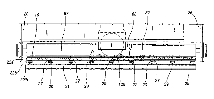
Means 27 are also provided to support the fabric work plane
in such a way that the elastic compliance of the work plane is
contained within a predefined limit value and which prevents the
superficial scratching of the work plane.
These means 27 support the work plane in such a way that -
in the section between adjacent support means - it presents a
predefined degree of elasticity or deflection and which remains
CA 02489161 2004-12-09
WO 03/103907 PCT/IB03/02501
7
within the limit of the elastic deformation of the work plane and
which moreover makes it possible to prevent the surface scratching
of the work plane.
It is possible, in this way, to provide a countering action
to the cutting blade, which is sufficient to allow accurate
cutting of the fabric and at the same time to prevent the surface
scratching of the work plane.
Advantageously, these support means 27 of the work plane are
in the form of elastically yielding support means.
As figures 4 and 5 show, these work plane support means
comprise a plurality of support means 27 on which the fabric work
plane rests.
As shown, in particular, in figures 4 and 5, the adjacent
elements of the support means are spaced at a predefined distance
from each other, indicated by the reference letter d in figure 4.
Advantageously, this distance d can vary between 320 and 400
mm, and, as illustrated in the attached figures, is preferably 360
mm.
As clearly shown in the attached figure 4, these means
provide supports 27 (shown with dashed lines), which axe
substantially pointed and distributed on the lower surface of the
work plane in'such a way that adjacent supports 27 represent the
corners of a virtual quadrilateral (as shown in figure 4), in
particular, according to this preferred embodiment, the corners of
a square.
This provides a support structure of the work plane which
allows sufficient elastic deformation to prevent the work plane
from being scratched on its upper surface, and to allow accurate
cutting of the shaped portions of the fabric by the blade.
As shown in figure 4, these support elements 27 are arranged
in transverse lines at a certain distance apart. These lines are
parallel to each other and at a certain longitudinal distance
apart. These support elements 27 are arranged in such a way that
the elements in a transverse line are positioned longitudinally
between corresponding elements of the adjacent longitudinal line.
This provides a good distribution of the support elements,
making it possible to support the work plane 22 in a substantially
CA 02489161 2004-12-09
WO 03/103907 PCT/IB03/02501
8
uniform manner.
In practice, the supports 27 which are substantially pointed
and elastically yielding in an axial direction, i.e. in a vertical
or perpendicular direction to the work plane, provide sufficient
vertical flexibility, when the cutting blade passes over or close
to the support (allowing the work plane to yield and prevent the
glass surface from being scratched), while vertical flexibility is
provided - at the centre line points between one support and the
next - by the bending flexibility of the work plane. In the
sections between the centre line point - between one support and
the next - and the supports, the elastic flexibility is
substantially an interpolation of the two types of flexibility,
bending of the work plane and axial or vertical flexibility of the
elastic support.
Each support element of the fabric work plane advantageously
comprises a respective pad 27, made from elastomeric material,
with a circular cross-section, which not only allows elastic
deformation of the work plane, preventing the scratching of the
glass surface, but is also sufficient to prevent the creation of
peaks of stress localised in correspondence with the support
points.
Other elastic means could, however, be used instead of this
elastomeric pad.
As shown in the attached figures 2 and 5, each elastomeric
pad 27 is supported by a cup-shaped element 29, which presents a
circular cross-section housing, in metal, preferably steel, which
holds the lower part of the elastomeric pad 27 and is supported by
a vertical stem protruding from a corresponding transverse beam 31
of this apparatus, this beam 31 being designed to support a
corresponding transverse row of support elements 27.
In particular, a plurality of these transverse beams 31 are
foreseen, supporting respective rows of these support elements 27,
which are arranged longitudinally at a certain distance from each
other.
Fabric cutting means are also foreseen in the form of a
circular blade 20, in steel, which rotates on the fabric in order
to cut it.
CA 02489161 2004-12-09
WO 03/103907 PCT/IB03/02501
9
The blade moves over the fabric work plane according to
predefined linear pathways in order to out the shaped portions of
the fabric and also moves vertically, between a lowered working
and fabric cutting position and a raised position - during which
the blade moves, parallel to the work plane, from the end point of
a cut to a subsequent start point of a new cut, without performing
any cutting action during this movement.
The cutting blade 20 turns or rotates perpendicularly to the
work plane 22 - by rotation of its support axis - according to
predefined directional angles in order to perform longitudinal,
transverse and oblique cuts or cuts of any predefined
conformation, also including or consisting of curved sections.
This blade presents a cutting edge 120, with a radius of
curvature R' advantageously between 30 and 50 mm, preferably 42,5
Z5 mm, as shown in figure 8.
As clearly shown in figure 6, this blade also presents a
radial extremity 121 which comes into contact with and cuts the
fabric and a first 123 and second 125 surface converging on the
cutting extremity, in which this cutting extremity defines an
arched surface advantageously having a radius of curvature r'
between 0,15 and 0,25 mm, preferably 0,2 mm, while the converging
surfaces slope, respectively, at an angle between 16° and 20°,
preferably 20'° with respect to the vertical V.
This makes it possible, to achieve a specific pressure on the
fabric to be cut and which is sufficient to provide an accurate
cut and at the same time a specific pressure on the material which
constitutes the surface of the work plane, which advantageously
remains below the breaking or cutting limit of this material and
thus prevents its surface from being scratched, guaranteeing
thereby a long working life of the surface and thus of the work
plane.
The deformation of the work plane caused by the blade 22
when it is at the centre line point between two support elements
is illustrated in figures 7 and 8. Figures 7 and 8 illustrate two
limit conditions with the blade turned in angular directions at
right angles to each other. The weight which the blade exerts on
the work plane 22, in these load conditions, elastically deforms
CA 02489161 2004-12-09
WO 03/103907 PCT/IB03/02501
the work plane until it reaches a predefined deflection f at the
centre line point, such as not to damage the work plane material
but to provide elastic compliance that prevents any risk of
surface scratching of the material.
5 Support means of the cutting blade are provided in the form
of a vertical shaft 40 defined by the stem of a pneumatic cylinder
41, which is designed to impart a force F of the blade on the work
plane 22, which is advantageously between 15 and 30 kg, and is
preferably 20 kg.
10 These support means of the blade are suitable to bring the
cutting blade into contact with the fabric, with a predefined
pressure, to make the cut, by rotating the blade on its fulcrum
pin 40', and to raise the blade above the fabric just in order to
move it.
The blade support means are connected to the frame of this
apparatus by means of transverse beams 24, which are constrained -------
by corresponding metal side plates 26, 28.
Appropriate means, not shown in the attached drawings; move
these cutting blade support means longitudinally along the work
plane.
Means are provided which rotate the blade-holder shaft 40
with respect to its vertical axis. These shaft rotation means are
the same as those described in the aforesaid document WO 01139941
and are, therefore, not described again in detail here.
For each cutting unit, means are also provided which are
designed to block a corresponding portion of material while it is
being cut.
These means designed to block the material to be cut are in
the form of a first 87 and second 88 roller, between which the
cutting blade 20 extends.
The material between the rollers 87, 88 is held taut thanks
to the fact that it is blocked laterally by the restraining action
of each roller on the material, pressing it against the upper
surface of the work plane 22.
According to a preferred embodiment, it is also foreseen
that the rollers 87 and 88, blocked in a non-rotating condition,
are pulled downstream and drag the cut material with them to
CA 02489161 2004-12-09
WO 03/103907 PCT/IB03/02501
I1
transfer it to a material pick-up zone.
At the same time, a new length of material is fed into the
cutting zone T.
During these stages, the material slides over the upper
surface of the work plane under the pressure exerted.by the
blocking rollers.
These first and second rollers 87, 88 are supported in a
freely turning fashion by metal side plates 26, 28.
According to one aspect of this invention, the cutting blade
20 exerts a specific pressure on the fabric, which is sufficient
to accurately and decisively cut this material - whatever the type
and features of this fabric material to be cut - while this
specific pressure is not sufficient to cause localised breaks or
damage to the underlying surface of the work plane and cutting
blade counter-element.
Considering glass as having an elastic modulus (Young's
modulus) equal to 7x101° PA (Pascal) and a Poisson modulus equal
to 0,2 it is possible to ascertain that, on the conditions
established above, under the weight of the cutting blade load, the
glass plane is elastically distorted with maximum deflection f,
this remaining within the range of elastic deformation, with no
breakage of the work plane.
While this embodiment of the apparatus is suitable for
obtaining the best result, also in terms of working life and
resistance to wear, it is believed that the use of even only some
or one of the above-mentioned features of the apparatus is highly
advantageous.
The invention described above is subject to numerous
modifications and variations, all within the scope of the
inventive concept. Moreover, all the details of the invention may
be substituted by technically equivalent elements. .