Language selection

Search

Patent 2489213 Summary

Third-party information liability

Some of the information on this Web page has been provided by external sources. The Government of Canada is not responsible for the accuracy, reliability or currency of the information supplied by external sources. Users wishing to rely upon this information should consult directly with the source of the information. Content provided by external sources is not subject to official languages, privacy and accessibility requirements.

Claims and Abstract availability

Any discrepancies in the text and image of the Claims and Abstract are due to differing posting times. Text of the Claims and Abstract are posted:

  • At the time the application is open to public inspection;
  • At the time of issue of the patent (grant).
(12) Patent: (11) CA 2489213
(54) English Title: ROLLER CAGE ASSEMBLY
(54) French Title: ENSEMBLE CAGE DE ROULEAU A PEINTURE
Status: Expired and beyond the Period of Reversal
Bibliographic Data
(51) International Patent Classification (IPC):
  • B05C 17/02 (2006.01)
(72) Inventors :
  • GARTNER, PERRY (United States of America)
(73) Owners :
  • BRENNER INTERNATIONAL CORP.
(71) Applicants :
  • BRENNER INTERNATIONAL CORP. (United States of America)
(74) Agent: HILL & SCHUMACHER
(74) Associate agent:
(45) Issued: 2007-01-16
(86) PCT Filing Date: 2002-11-15
(87) Open to Public Inspection: 2003-12-24
Examination requested: 2004-12-10
Availability of licence: N/A
Dedicated to the Public: N/A
(25) Language of filing: English

Patent Cooperation Treaty (PCT): Yes
(86) PCT Filing Number: PCT/US2002/036578
(87) International Publication Number: US2002036578
(85) National Entry: 2004-12-10

(30) Application Priority Data:
Application No. Country/Territory Date
10/064,127 (United States of America) 2002-06-13

Abstracts

English Abstract


A roller assembly to support paint rollers comprises a cage mounted on a
roller shaft having spaced elongated bars integrally supported by dual flange
support members at intervals therealong and terminating in end portions that
engage an inner end cap and an outer end cap. The inner end cap includes
outer tapered fingers and raised tabs, which engage and hold a paint roller
for
ease of insertion and removal.


French Abstract

Ensemble (10) cage pour maintenir des rouleaux à peinture, qui comprend une cage (11) montée sur un manche (15) de rouleau, des tiges (40) allongées espacées et maintenues d'un seul tenant par des éléments supports (37a-f) à deux brides placés à intervalles donnés le long de la tige, et qui se terminent par des parties d'extrémité (19, 32) s'assemblant à un capuchon d'extrémité intérieur et à un capuchon d'extrémité extérieur. Le capuchon d'extrémité (19) intérieur comprend des doigts (24a-f) coniques extérieurs et des languettes (41) en relief qui se mettent en prise avec un rouleau à peinture et le retiennent, de manière à faciliter l'insertion et le retrait de celui-ci.

Claims

Note: Claims are shown in the official language in which they were submitted.

Claims
1. A roller cage assembly for use in association with a paint roller
comprising:
a handle having a shaft extending outwardly therefrom, said shaft having
a cage shaft portion extending perpendicular to the handle;
a cage mounted rotatably about the cage shaft portion having a plurality of
circumferentially spaced axial elongated bars positioned about the cage shaft
portion, a plurality of axially spaced substantially circular support members
connecting the bars, the cage having inboard and outboard end portions, each
end portion having an aperture to receive the cage shaft portion; and,
an outboard end cap mounted at the outboard cage end portion and an
inboard end cap mounted about the inboard cage end portion, said inboard end
cap further including a plurality of axially extending tapered fingers to
facilitate
mounting of the paint roller and a plurality of raised tabs to grip the paint
roller
and an aperture extending therethrough to accommodate the cage shaft portion
when the paint roller is inserted over the cage.
2. A roller cage assembly for paint rollers in accordance with claim 1 further
including:
a projecting stop on an inboard end of the cage shaft portion and a
washer slidably mounted on the cage shaft portion adjacent the projecting stop
to retain the inboard end cap to limit movement of the cage on the cage shaft
portion.
3. A roller cage assembly for paint rollers in accordance with claim 2 further
including:
a bearing mounted in each end portion of the cage to rotatably mount the
cage on the cage shaft portion at the inboard end of said cage shaft portion
and
an outboard end of said cage shaft portion to permit rotation of the cage.
6

4. A roller cage assembly for paint rollers in accordance with any one of
claims 1 to 3 wherein:
the support members each comprise circular double flange portions and
circular cross portions joining the double flange portions.
5. A roller cage assembly for paint rollers in accordance with any one of
claims 1 to 4 wherein:
the elongated bars comprise 4 bars spaced circumferentially at 90°
apart
from one another; said bars being integrally formed with the support members.
6. A roller cage assembly for paint rollers in accordance with any one of
claims 1 to 5 wherein:
the end portions of the cage each comprise a flange portion and a
recessed cylinder extending outwardly from the flange to retain the end caps.
7. A roller cage assembly for paint rollers in accordance with claim 6
wherein:
the tabs each comprise a portion extending radially outwardly from the
fingers, a raised intermediate portion for gripping the roller, and a portion
extending radially inwardly to an outer flange of the inboard end cap, said
tabs
each extending from the midpoint of a finger to the outer flange of the
inboard
end cap.
8. A roller cage assembly for paint rollers in accordance with any one of
claims 1 to 7 wherein:
the outboard end cap is fixedly mounted about the end portion of the
cage.
9. A roller cage assembly for paint rollers in accordance with any one of
claims 1 to 8 wherein:
7

the cage is plastic; and
the support members comprise three spaced members integrally molded
with the elongated bars.

Description

Note: Descriptions are shown in the official language in which they were submitted.


CA 02489213 2006-O1-31
ROLLER CAGE ASSEMBLY
BACKGROUND OF INVENTION
This invention relates to paint rollers and cage assemblies and
particularly to a novel assembly that securely fastens the roller cover in
place
and yet permits the roller cover to be quickly and easily removed. Tapered
prongs and configured tabs which are positioned in a predetermined spaced
array on the inward end cap facilitate insertion of the roller cover and
maintain
the roller cover in position during use. The inward cap is force fit on one
end of
the cage while the outward end cap is fixedly secured to the other end of the
cage.
In the prior art, paint rollers often become loose during use. If an
attempt is made to secure the roller to an inner cage, it is often difficult
to
dislodge the roller after use. This invention solves this problem with its
unique
cage and end cap structure which facilitates installation of the roller,
maintains,
the roller in position during use and permits removal of the roller.
In the prior art, U.S. Patent No. 5,345,648 is directed to a paint
roller, which uses a Bellville type spring washer to hold the roller in
position on a
particular cage design. This design is more expensive and more complicated
than the present invention. The proposed invention is easy to use, inexpensive
and superior to prior art devices.
Other patents exist in this crowded art but do not affect the
patentability of the invention.
SUMMARY OF INVENTION
This invention relates to plastic cage frame assemblies for paint
rollers. A roller is mounted over a cage frame which includes an axial metal
shaft
1

CA 02489213 2006-O1-31
(hereafter, referred to as "cage shaft") extending between an inward end cap
and
an outboard end cap, said shaft comprising an outer end portion of the handle
shaft. The other end of the handle shaft is perpendicular to the midpoint of
the
cage shaft and includes a handle mounted thereon. The roller cage comprises
opposite end portions, which fixedly engage the respective end caps at a
predetermined distance from the cage shaft. A plurality of spaced plastic bars
extends axially parallel to the axial shaft between the end caps. The axial
bars
are spaced at 90° intervals about the periphery of the cage and are
joined by
circular support members along their length and have end caps at each end
thereof.
End caps engage the end portions of the cage to confine the cage
in place. The inboard end cap includes an outer flange leading to a recessed
cylindrical portion having a plurality of tapered gripping members at the
inner end
thereof. A plurality of projecting configured tabs are located in the
cylindrical
recess each at approximately the mid-point of a corresponding gripping member
and extend from said gripping member to the outer flange. The gripping
members and the tabs engage the roller, which is slid over the cage between
the
end caps. This design securely fastens the roller to the cage and permits the
roller to be quickly and easily removed after use.
Accordingly, an object of this invention is to provide a new and
improved roller assembly for painting.
Another object of this invention is to provide a new and improved
rotational roller cage assembly to engage and hold paint rollers.
A further object of this invention is to provide a new and improved
roller cage assembly for painting that includes an inboard end cap having a
plurality of spaced tapered gripping members to facilitate engagement and
disengagement of a paint roller.
A mare specific object of this invention is to provide a new and
improved paint roller and cage assembly which includes a cage having a
plurality
of spaced axial bars joined by circular support members at various positions
2

CA 02489213 2006-O1-31
along their length, end portions engaging a centrally located cage shaft, and
an
inboard end cap mounted to a first cage end having tapered gripping members
and projecting tabs to engage and hold the roller and an outer end cap fixedly
mounted to a second cage end portion.
Accordingly, in one aspect of the invention, there is provided a
roller cage assembly for use in association with a paint roller comprising:
a handle having a shaft extending outwardly therefrom, said shaft
having a cage shaft portion extending perpendicular to the handle;
a cage mounted rotatably about the cage shaft portion having a
plurality of circumferentially spaced axial elongated bars positioned about
the
cage shaft portion, a plurality of axially spaced substantially circular
support
members connecting the bars, the cage having inboard and outboard end
portions, each end portion having an aperture to receive the cage shaft
portion;
and,
an outboard end cap mounted at the outboard cage end portion
and an inboard end cap mounted about the inboard cage end portion, said
inboard end cap further including a plurality of axially extending tapered
fingers
to facilitate mounting of the paint roller and a plurality of raised tabs to
grip the
paint roller and an aperture extending therethrough to accommodate the cage
shaft portion when the paint roller is inserted over the cage.
BRIEF DESCRIPTION OF DRAWINGS
The above and other objects and advantages of this invention may
be more clearly seen when viewed in conjunction with the accompanying
drawings wherein.
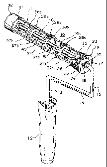
FIG. 1 is a perspective view of the roller cage assembly comprising
the invention.
FIG. 2 is a perspective view of the roller cage.
3

CA 02489213 2006-O1-31
FIG. 3 is a perspective view of the inboard end cap; and
FIG. 4 is a perspective view of the outboard end cap.
DETAILED DESCRIPTION
Referring now to the drawings, FIG. 1 discloses a perspective view
of the invention which comprises a paint roller assembly 10 with a unique cage
assembly 11. The roller assembly 10 includes a handle 12 having a metal shaft
portion 13 extending outwardly therefrom, a shaft portion 14 at a right angle
thereto and a further shaft portion 15 extending outwardly substantially
parallel to
the handle 12 and the shaft portion 13. A cage shaft portion 16 extends at a
right
angle to shaft portion 15 to engage the cage assembly 11 and is substantially
parallel to shaft portion 14 and at a spaced distance therefrom.
A stop 17, washer 35, and bearing 18 are located on the inboard
end of cage shaft portion 16. An inboard plastic end cap 19 includes a central
aperture 21 to engage the cage shaft 16 and bearing 18. The end cap 19 is held
in position by the stop 17, which engages washer 35. The end cap 19 includes
an outer flange 22, an intermediate recessed cylindrical portion 23 and a
plurality
of spaced gripping members or fingers 24a-f at the inner end thereof. The
gripping members 24a-f extend outwardly from the cylinder portion 23 and then
each taper downwardly along surface 25a-f to the end of said gripping members
24a-f. Typically six gripping members 24a-f would be used. The end cap 19 also
includes a configured tab 41 extending from the mid-point of each gripping
member 24a-f to the flange 22. The tabs 41 include a portion 42 sloping
upwardly from the gripping members 24a-f, a raised intermediate portion 43 to
engage the roller and an inboard portion 44 which slopes downwardly to the
flange 22.
The cage 11 includes inner end portion 36 with an outwardly
extending flange 30 and an end cylindrical portion 27 mounted within the end
cap 19. The end portion 36 has a central aperture 28 having bearing 18 located
4

CA 02489213 2006-O1-31
therein. A plurality of support members 29a-29c are located at intervals along
the
cage 11 while flange portions 30 and 31 are located at opposite ends of the
cage
11. Support members 29a-c include a double flanged construction which engage
four parallel axial elongated bars 40 spaced at 90° intervals about the
cage 11
parallel to the cage shaft portion 16. The double flange construction comprise
circular flanges 37a-37b, 37c-37d, 37e-37f each joined by a cross portion 38a,
38b and 38c. The outboard end cap 32 is cylindrical in configuration and
engages the cage shaft 16 which extends through aperture 33 mounted therein.
The outboard end cap 32 is fixedly mounted to the cage 11 although in an
alternate embodiment, the end caps 19, 32 may rotate independent of cage 11.
In use, a roller (not shown) is slid over the cage assembly 11
against the flange 22 on the end cap 19. The gripping members 24 and
particularly the tabs 41 engage the interior of the roller to hold it securely
in
position. The roller is thus easily mounted and removed but is held securely
in
place during use by the tapered gripping members 24, the cage 11 and
supporting bars 40 and gripping members 29a-c. The roller cage assembly is
free to rotate around the cage shaft portion 16.
While the invention has been explained by a detailed description of
certain specific embodiments, it is understood that various modifications and
substitutions can be made in any of them within the scope of the appended
claims that are intended also to include equivalents of such embodiments.
5

Representative Drawing
A single figure which represents the drawing illustrating the invention.
Administrative Status

2024-08-01:As part of the Next Generation Patents (NGP) transition, the Canadian Patents Database (CPD) now contains a more detailed Event History, which replicates the Event Log of our new back-office solution.

Please note that "Inactive:" events refers to events no longer in use in our new back-office solution.

For a clearer understanding of the status of the application/patent presented on this page, the site Disclaimer , as well as the definitions for Patent , Event History , Maintenance Fee  and Payment History  should be consulted.

Event History

Description Date
Time Limit for Reversal Expired 2018-11-15
Letter Sent 2017-11-15
Inactive: Late MF processed 2016-11-11
Letter Sent 2015-11-16
Inactive: Late MF processed 2012-11-09
Letter Sent 2011-11-15
Inactive: Late MF processed 2009-10-28
Letter Sent 2008-11-17
Grant by Issuance 2007-01-16
Inactive: Cover page published 2007-01-15
Pre-grant 2006-10-31
Inactive: Final fee received 2006-10-31
Notice of Allowance is Issued 2006-05-02
Letter Sent 2006-05-02
Notice of Allowance is Issued 2006-05-02
Inactive: Approved for allowance (AFA) 2006-04-06
Amendment Received - Voluntary Amendment 2006-01-31
Inactive: S.30(2) Rules - Examiner requisition 2005-10-05
Amendment Received - Voluntary Amendment 2005-08-31
Letter Sent 2005-04-07
Inactive: S.30(2) Rules - Examiner requisition 2005-03-02
Inactive: Single transfer 2005-02-17
Inactive: Cover page published 2005-01-25
Advanced Examination Determined Compliant - paragraph 84(1)(a) of the Patent Rules 2005-01-24
Letter sent 2005-01-24
Inactive: Applicant deleted 2005-01-21
Inactive: Courtesy letter - Evidence 2005-01-21
Letter Sent 2005-01-21
Inactive: Acknowledgment of national entry - RFE 2005-01-21
Application Received - PCT 2005-01-19
National Entry Requirements Determined Compliant 2004-12-10
Request for Examination Requirements Determined Compliant 2004-12-10
Inactive: Advanced examination (SO) fee processed 2004-12-10
All Requirements for Examination Determined Compliant 2004-12-10
National Entry Requirements Determined Compliant 2004-12-10
Application Published (Open to Public Inspection) 2003-12-24

Abandonment History

There is no abandonment history.

Maintenance Fee

The last payment was received on 2006-10-31

Note : If the full payment has not been received on or before the date indicated, a further fee may be required which may be one of the following

  • the reinstatement fee;
  • the late payment fee; or
  • additional fee to reverse deemed expiry.

Patent fees are adjusted on the 1st of January every year. The amounts above are the current amounts if received by December 31 of the current year.
Please refer to the CIPO Patent Fees web page to see all current fee amounts.

Owners on Record

Note: Records showing the ownership history in alphabetical order.

Current Owners on Record
BRENNER INTERNATIONAL CORP.
Past Owners on Record
PERRY GARTNER
Past Owners that do not appear in the "Owners on Record" listing will appear in other documentation within the application.
Documents

To view selected files, please enter reCAPTCHA code :


To view images, click a link in the Document Description column. To download the documents, select one or more checkboxes in the first column and then click the "Download Selected in PDF format (Zip Archive)" or the "Download Selected as Single PDF" button.

List of published and non-published patent-specific documents on the CPD .

If you have any difficulty accessing content, you can call the Client Service Centre at 1-866-997-1936 or send them an e-mail at CIPO Client Service Centre.


Document
Description 
Date
(yyyy-mm-dd) 
Number of pages   Size of Image (KB) 
Representative drawing 2004-12-09 1 24
Drawings 2004-12-09 2 70
Claims 2004-12-09 2 69
Abstract 2004-12-09 2 69
Description 2004-12-09 5 185
Description 2005-08-30 5 208
Drawings 2005-08-30 2 65
Abstract 2005-08-30 1 11
Claims 2005-08-30 3 74
Description 2006-01-30 5 213
Claims 2006-01-30 3 78
Representative drawing 2006-12-18 1 15
Acknowledgement of Request for Examination 2005-01-20 1 176
Notice of National Entry 2005-01-20 1 200
Courtesy - Certificate of registration (related document(s)) 2005-04-06 1 105
Commissioner's Notice - Application Found Allowable 2006-05-01 1 162
Maintenance Fee Notice 2008-12-28 1 171
Late Payment Acknowledgement 2009-11-08 1 162
Maintenance Fee Notice 2011-12-27 1 171
Late Payment Acknowledgement 2012-11-08 1 164
Maintenance Fee Notice 2017-12-26 1 180
Maintenance Fee Notice 2015-12-28 1 171
Late Payment Acknowledgement 2016-11-10 1 162
PCT 2004-12-09 1 52
Correspondence 2004-12-23 2 95
Correspondence 2005-01-20 1 25
PCT 2004-12-09 4 181
PCT 2004-12-09 1 60
Fees 2005-10-13 1 34
Correspondence 2006-10-30 1 36
Fees 2006-10-30 1 33
PCT 2004-12-09 1 51
Fees 2007-09-19 1 35
Fees 2009-10-27 1 45
Fees 2013-11-06 1 24
Fees 2014-11-06 1 25
Fees 2016-11-10 1 26