Language selection

Search

Patent 2489651 Summary

Third-party information liability

Some of the information on this Web page has been provided by external sources. The Government of Canada is not responsible for the accuracy, reliability or currency of the information supplied by external sources. Users wishing to rely upon this information should consult directly with the source of the information. Content provided by external sources is not subject to official languages, privacy and accessibility requirements.

Claims and Abstract availability

Any discrepancies in the text and image of the Claims and Abstract are due to differing posting times. Text of the Claims and Abstract are posted:

  • At the time the application is open to public inspection;
  • At the time of issue of the patent (grant).
(12) Patent Application: (11) CA 2489651
(54) English Title: REFLECTOR LAMP WITH REDUCED SEAL TEMPERATURE
(54) French Title: LAMPE A REFLECTEUR ASSURANT LA REDUCTION DE TEMPERATURE DU JOINT
Status: Deemed Abandoned and Beyond the Period of Reinstatement - Pending Response to Notice of Disregarded Communication
Bibliographic Data
(51) International Patent Classification (IPC):
  • F21V 7/10 (2006.01)
  • F21V 7/04 (2006.01)
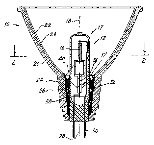
  • F21V 29/10 (2015.01)
  • H01J 5/32 (2006.01)
  • H01J 61/36 (2006.01)
(72) Inventors :
  • KLING, MICHAEL R. (Cayman Islands)
  • BUSCHMANN, JEFFREY P. (Cayman Islands)
(73) Owners :
  • OSRAM SYLVANIA INC.
(71) Applicants :
  • OSRAM SYLVANIA INC. (United States of America)
(74) Agent: SMART & BIGGAR LP
(74) Associate agent:
(45) Issued:
(22) Filed Date: 2004-12-07
(41) Open to Public Inspection: 2005-09-15
Availability of licence: N/A
Dedicated to the Public: N/A
(25) Language of filing: English

Patent Cooperation Treaty (PCT): No

(30) Application Priority Data:
Application No. Country/Territory Date
10/800,500 (United States of America) 2004-03-15

Abstracts

English Abstract


A lamp assembly 10 has a light source 12 having two sealed electrodes 14, 16,
sealed in a
seal area 17 and defining a lamp axis 18. A concave shell 20 has an internal
surface 22 with
a reflective surface 23 formed thereon. The concave shell 20 has a neck 24
defining a neck
cavity 26 and a reflector axis 28. The neck 24 is provided with an electrical
connection 30
and a mechanical support for the light source12. The shell 20 surrounds the
source 12 to
reflect light from the source 12 to a field to be illuminated during lamp
operation. The
source 12 and the reflector surface 23 are oriented with the lamp axis18
substantially co-axial
with the reflector axis 28, and at least a portion of at least one of the
electrodes, for example,
14, extends into the neck cavity 26. A zone 32 is formed in the neck cavity 26
for
substantially redirecting specular reflection away from the seal area.


Claims

Note: Claims are shown in the official language in which they were submitted.

Page 8
CLAIMS:
What is claimed is:
1. A lamp assembly comprising:
a light source having two sealed electrodes sealed in a seal area and defining
a lamp
axis;
a concave shell having an internal surface with a reflective surface formed
thereon,
said shell having a neck defining a neck cavity and a reflector axis, said
neck being provided
with an electrical connection and a mechanical support for said light source;
said shell surrounding said source to reflect light from said source to a
field to be
illuminated during lamp operation, said source and said reflector being
oriented with said
lamp axis to be substantially co-axial with said reflector axis, and at least
a portion of at least
one of said electrodes extending in said neck cavity; and
a zone formed in said neck cavity for substantially redirecting specular
reflection
away from said seal area.
2. The lamp assembly of Claim 1 wherein said zone comprises a plurality of
facets
arrayed about the surface of neck cavity.
3. The lamp assembly of Claim 1 wherein said zone comprises a stippled pattern
arrayed
about the surface of said neck cavity.
4. The lamp assembly of Claim 1 wherein said zone comprises a plurality of
closely
spaced longitudinal grooves arrayed about the surface of said neck cavity.

Description

Note: Descriptions are shown in the official language in which they were submitted.


CA 02489651 2004-12-07
Attorney Docket No.: 03-1-528
Page 2
REFLECTOR LAMP WITH REDUCED SEAL TEMPERATURE
001. TECHNICAL FIELD
002. This invention relates to electric lamps and more particularly to
electric lamps
enclosed in a reflector. Still more particularly, the invention relates to a
parabolic
reflector lamp (PAR) with a ceramic metal halide arc capsule having a reduced
seal
temperature.
003. BACKGROUND ART
004. Ceramic lamp envelopes with modern metal halide arc capsules have created
a
new class of metal halide lamp, see, for example, Geven, et al. in U.S. Patent
No.
5,424,609 and Carleton et al. in J. Ill. Eng. Soc. P139-145, Winter, 1996
(Proc. of
IESNA Annual Conference). These lamps contain metal halide fill chemistries
and
two electrodes. A high voltage pulse between the electrodes is used to ignite
the
lamp. Normal current and voltage are then applied through the electrodes to
excite
the enclosed gas and fill materials to a plasma state. Typical fills include
rare earth
halides with various other additives, which can include thallium halide and
calcium
halide, in addition to an inert starting gas such as argon or xenon.
005. The ceramic arc tube is often jacketed in another envelope, called an
outer jacket,
to protect the inner arc tube from the atmosphere. Many of the lamp parts,
especially
the niobium in-leads, oxidize rapidly if exposed to air at the lamp operating
temperatures, causing the lamp to fail. These outer jackets are usually
thermally
isolated from the arc tube by construction and contain a vacuum or are filled
with a
partial pressure of an inert gas and a getter material, for example, a
zirconium and
aluminum compound, to getter oxygen and hydrogen.
006. Often, the inner arc tube and outer jacket are mounted inside a parabolic
reflector
to gather and direct the generated light from the lamp in a useful beam
pattern. This
can be a flood or a spot beam for illumination of interior surfaces or
building facades
in exterior applications. Such lamps with halogen light sources are also
commonly

CA 02489651 2004-12-07
' Attorney Docket No.: 03-1-528
Page 3
used for illuminating merchandise in stores and outside lighting in
residential
applications, for example, in security lighting. There is great interest in
using ceramic
metal halide lamps in the applications cited since they are efficient and
provide
excellent color rendering. The true colors of merchandise are rendered almost
as if
they were displayed in sunlight.
007. Economies of scale dictate using the same reflector for the new ceramic
metal
halide lamps (HCI lamps) as were used for halogen lamps. This keeps
manufacturing
costs to a minimum. It also allows the lamps to be used in existing fixtures.
008. Unfortunately, life tests have shown that the HCI lamps mounted in
existing lamp
structures fail prematurely at about 1500-200 hours, instead of progressing to
their
rated life expectancy of 10,00 hours. This is attributed to the rapid chemical
attack by
the fill material on the sealing glass (frit) used to make conventional HCI
seals, (see
1 S Geven et al., supra). The problem is exacerbated when the lamps are run in
the base
up configuration, as they are used in many interior down-lighting
applications. The
seal is then subject to greater heat and therefore more active chemical
reactions. To
be a useful product in the markets mentioned, the lifetime of the lamp must be
extended.
009. U.S. Published Patent Application No. 2003/0193280, published Oct. 16,
2003,
and which is owned by the assignee of the instant invention, has attempted to
at least
partially solve the problem by interposing a light absorbing layer in the neck
of the
lamp, whereby extraneous light is converted to heat in the layer and then re-
radiated
in an unfocused manner with only a small portion of it being redirected to the
seal
area. The Publication suggests that the light-absorbing layer can be a black
top
coating on the neck interior or exterior. Alternatively, means can be provided
during
manufacture so that the neck portion is not metallized. While this procedure
works
for its intended purpose, it introduced other problems. For example, the
solution is

CA 02489651 2004-12-07
Attorney Docket No.: 03-1-528
Page 4
costly to implement and degrades lamp performance and appearance. The coating
in
the neck must be manually removed by mechanical or chemical means or,
alternatively, a masking device must be incorporated into the neck area for
the
metallization process. Some of the light entering the neck of a normal lamp is
reflected out of the lamp face and contributes to the total lumens. This light
contribution is lost when the neck is made transparent. Painting the neck or
using
colored glass adds considerable cost to the lamp and substantially alters the
appearance.
0010. DISCLOSURE OF INVENTION
0011. It is, therefore, an object of the invention to obviate the
disadvantages of the prior
art.
0012. It is another object of the invention to enhance ceramic metal halide
reflector
lamps.
0013. It is yet another object of the invention to reduce the heat delivered
to the seal
area of an HCI lamp during operation.
0014. These objects are accomplished, in one aspect of the invention, by a
lamp
assembly comprising: a light source having two sealed electrodes sealed in a
seal area
and defining a lamp axis; a concave shell having an internal surface with a
reflective
surface formed thereon, said shell having a neck defining a neck cavity and a
reflector
axis, said neck being provided with an electrical connection and a mechanical
support
for said light source; said shell surrounding said source to reflect light
from said
source to a field to be illuminated during lamp operation, said source and
said
reflector being oriented with said lamp axis to be substantially co-axial with
said
reflector axis, and at least a portion of at least one of said electrodes
extending in said

CA 02489651 2004-12-07
Attorney Docket No.: 03-1-528
Page S
neck cavity, and a zone formed in said neck cavity for substantially
redirecting
specular reflection away from said seal area.
0015. Since it has been determined that a primary cause of the overheating of
the arc
tube seal is the specular reflection from the discharge that is focused on a
sensitive
region of the seal, the redesigned neck cross-section described above
redirects this
energy away from the seal and greatly increases the life of the lamp. The
specular,
reflection-reducing zone is easily accomplished during the envelope
manufacture and
involves only an inexpensive plunger change for new tooling.
0016. BRIEF DESCRIPTION OF THE DRAWINGS
0017. Fig. 1 is a diagrammatic cross-sectional view of a lamp embodying an
aspect of
the invention;
0018. Fig. 2 is a cross-sectional plan view taken along the line 2-2 of Fig.
1;
0019. Fig. 3 is a cross-sectional plan view similar to Fig. 2 showing an
alternate
embodiment; and
0020. Fig. 4 is a similar view showing yet another alternate embodiment.
0021. BEST MODE FOR CARRYING OUT THE INVENTION
0022. For a better understanding of the present invention, together with other
and
further objects, advantages and capabilities thereof, reference is made to the
following disclosure and appended claims in conjunction with the above-
described
drawings.

CA 02489651 2004-12-07
Attorney Docket No.: 03-1-528
Page 6
0023. Referring now to the invention with greater particularity, there is
shown in Fig. 1
a lamp assembly 10 comprising: a light source 12 having two sealed electrodes
14,
16, sealed in a seal area 17 and defining a lamp axis 18. A concave shell 20
has an
internal surface 22 with a reflective surface 23 formed thereon. The concave
shell 20
has a neck 24 defining a neck cavity 26 and a reflector axis 28. The neck 24
is
provided with an electrical connection 30 and a mechanical support for the
light
sourcel2. The shell 20 surrounds the source 12 to reflect light from the
source 12 to a
field to be illuminated during lamp operation. The source 12 and the reflector
surface
23 are oriented with the lamp axis 18 to be substantially co-axial with the
reflector
axis 28, and at least a portion of at least one of the electrodes, for
example, 14,
extends into the neck cavity 26. A zone 32 is formed in the neck cavity 26 for
substantially redirecting specular reflection away from the seal area.
0024. In a preferred embodiment of the invention, as shown in Figs. 1 and 2,
the zone
32 formed in neck cavity 26 is provided with a plurality of longitudinal
grooves 38.
The arrows 40 indicate how the light is redirected away from the seal area 17.
0025. Figs. 3 and 4 illustrate alternate embodiments wherein the neck cavity
26 can be
provided with facets 42 or can be stippled, as at 44.
0026. Providing the neck region with the zone formed to redirect the specular
reflections
away from the seal area 17 reduces the heat delivered to the seal area and
greatly
enhances the life of the arc tube.
0027. It is very cost effective since any of the appropriate forms of
redirection can be
applied when the envelope is manufactured
0028. While there have been shown and described what are at present considered
to be
the preferred embodiments of the invention, it will be apparent to those
skilled in the

CA 02489651 2004-12-07
Attorney Docket No.: 03-1-528
Page 7
art that various changes and modification can be made herein without departing
from
the scope of the invention as defined by the appended claims.

Representative Drawing
A single figure which represents the drawing illustrating the invention.
Administrative Status

2024-08-01:As part of the Next Generation Patents (NGP) transition, the Canadian Patents Database (CPD) now contains a more detailed Event History, which replicates the Event Log of our new back-office solution.

Please note that "Inactive:" events refers to events no longer in use in our new back-office solution.

For a clearer understanding of the status of the application/patent presented on this page, the site Disclaimer , as well as the definitions for Patent , Event History , Maintenance Fee  and Payment History  should be consulted.

Event History

Description Date
Inactive: IPC removed 2022-02-07
Inactive: IPC assigned 2022-02-07
Inactive: IPC removed 2022-02-07
Inactive: IPC expired 2016-01-01
Inactive: IPC removed 2015-12-31
Inactive: IPC expired 2015-01-01
Inactive: IPC removed 2014-12-31
Application Not Reinstated by Deadline 2008-12-08
Time Limit for Reversal Expired 2008-12-08
Deemed Abandoned - Failure to Respond to Maintenance Fee Notice 2007-12-07
Inactive: IPC from MCD 2006-03-12
Application Published (Open to Public Inspection) 2005-09-15
Inactive: Cover page published 2005-09-14
Inactive: IPC assigned 2005-02-08
Inactive: First IPC assigned 2005-02-08
Inactive: Filing certificate - No RFE (English) 2005-01-25
Filing Requirements Determined Compliant 2005-01-25
Application Received - Regular National 2005-01-24
Letter Sent 2004-12-07

Abandonment History

Abandonment Date Reason Reinstatement Date
2007-12-07

Maintenance Fee

The last payment was received on 2006-11-15

Note : If the full payment has not been received on or before the date indicated, a further fee may be required which may be one of the following

  • the reinstatement fee;
  • the late payment fee; or
  • additional fee to reverse deemed expiry.

Please refer to the CIPO Patent Fees web page to see all current fee amounts.

Fee History

Fee Type Anniversary Year Due Date Paid Date
Registration of a document 2004-12-07
Application fee - standard 2004-12-07
MF (application, 2nd anniv.) - standard 02 2006-12-07 2006-11-15
Owners on Record

Note: Records showing the ownership history in alphabetical order.

Current Owners on Record
OSRAM SYLVANIA INC.
Past Owners on Record
JEFFREY P. BUSCHMANN
MICHAEL R. KLING
Past Owners that do not appear in the "Owners on Record" listing will appear in other documentation within the application.
Documents

To view selected files, please enter reCAPTCHA code :


To view images, click a link in the Document Description column. To download the documents, select one or more checkboxes in the first column and then click the "Download Selected in PDF format (Zip Archive)" or the "Download Selected as Single PDF" button.

List of published and non-published patent-specific documents on the CPD .

If you have any difficulty accessing content, you can call the Client Service Centre at 1-866-997-1936 or send them an e-mail at CIPO Client Service Centre.


Document
Description 
Date
(yyyy-mm-dd) 
Number of pages   Size of Image (KB) 
Description 2004-12-07 6 222
Abstract 2004-12-07 1 22
Claims 2004-12-07 1 32
Drawings 2004-12-07 2 56
Representative drawing 2005-08-19 1 13
Cover Page 2005-09-02 1 46
Courtesy - Certificate of registration (related document(s)) 2004-12-07 1 105
Filing Certificate (English) 2005-01-25 1 158
Reminder of maintenance fee due 2006-08-08 1 110
Courtesy - Abandonment Letter (Maintenance Fee) 2008-02-04 1 176