Language selection

Search

Patent 2489695 Summary

Third-party information liability

Some of the information on this Web page has been provided by external sources. The Government of Canada is not responsible for the accuracy, reliability or currency of the information supplied by external sources. Users wishing to rely upon this information should consult directly with the source of the information. Content provided by external sources is not subject to official languages, privacy and accessibility requirements.

Claims and Abstract availability

Any discrepancies in the text and image of the Claims and Abstract are due to differing posting times. Text of the Claims and Abstract are posted:

  • At the time the application is open to public inspection;
  • At the time of issue of the patent (grant).
(12) Patent Application: (11) CA 2489695
(54) English Title: BASIN ASSEMBLY
(54) French Title: ENSEMBLE DE LAVABO
Status: Deemed Abandoned and Beyond the Period of Reinstatement - Pending Response to Notice of Disregarded Communication
Bibliographic Data
(51) International Patent Classification (IPC):
  • A47K 01/04 (2006.01)
(72) Inventors :
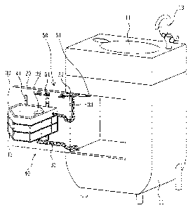
  • OUYOUNG, CRYSTAL (Taiwan, Province of China)
(73) Owners :
  • GLOBE UNION INDUSTRIAL CORP.
(71) Applicants :
  • GLOBE UNION INDUSTRIAL CORP. (Taiwan, Province of China)
(74) Agent: OYEN WIGGS GREEN & MUTALA LLP
(74) Associate agent:
(45) Issued:
(22) Filed Date: 2004-12-08
(41) Open to Public Inspection: 2006-03-01
Examination requested: 2005-02-04
Availability of licence: N/A
Dedicated to the Public: N/A
(25) Language of filing: English

Patent Cooperation Treaty (PCT): No

(30) Application Priority Data:
Application No. Country/Territory Date
2004200771970 (China) 2004-09-01

Abstracts

English Abstract


A basin assembly includes a hollow cabinet, a door pivotably
assembled on a middle of a front of the cabinet, a main basin on a top of the
cabinet, and an auxiliary basin fixed on the door. A main drain pipe
connects with a bottom of the main basin. A main faucet is arranged at the
top of the cabinet and neighboring the main basin. A main supply pipe
connects with a bottom of the main faucet. An auxiliary drain pipe is
arranged at a bottom of the auxiliary basin and joints the main drain pipe.
An auxiliary faucet is arranged adjacent the auxiliary basin and joints an
auxiliary supply pipe for providing water for the auxiliary basin. The
auxiliary supply pipe communicates with the main supply pipe. Therefore,
at least two users may use the basin assembly at the same time.
Additionally the auxiliary basin is lower than the main basin, which is
convenient for children to use.


Claims

Note: Claims are shown in the official language in which they were submitted.

Claims:
1. A basin assembly comprising a hollow cabinet, a main basin with
large size at a top of the cabinet, a main drain pipe at a bottom of the
main basin, a main faucet at the top of the cabinet and neighboring the
main basin, a main supply pipe connecting with a bottom of the main
faucet;
wherein a door is pivotably assembled on a middle of a front of the
cabinet, an auxiliary basin with small size being fixed on the door, an
auxiliary drain pipe being arranged at a bottom of the auxiliary basin
and jointing the main drain pipe, an auxiliary faucet being arranged
adjacent the auxiliary basin and jointing an auxiliary supply pipe for
providing water for the auxiliary basin, and the auxiliary supply pipe
communicating with the main supply pipe.
2. The basin assembly as claimed in claim 1, wherein the main faucet
and the auxiliary faucet are mechanical faucet or electrical faucet.
3. The basin assembly as claimed in claim 1, further comprising an
adjusting device, which includes two fastening plates vertically fixed
on the door, wherein the fastening plates define a plurality of holes
spaced the same distance from each other, and wherein a bracket is
anchored at the holes and has a profile relatively larger than that of the
auxiliary basin for supporting the auxiliary basin.
4. The basin assembly as claimed in claim 1, further comprising a
positioning device, which includes a plurality of hooks fixed on the
door and the cabinet, and a plurality of hanging plates clasping the
hooks for positioning the door at different angles with respective to
the cabinet.
5. The basin assembly as claimed in claim 1, wherein the auxiliary drain
pipe is flexible.
7

6. The basin assembly as claimed in claim 1, wherein the auxiliary
supply pipe is flexible.
8

Description

Note: Descriptions are shown in the official language in which they were submitted.


CA 02489695 2004-12-08
SPECIFICATION
BASIN ASSEMBLY
BACKGROUND OF THE INVENTION
1. FIELD OF THE INVENTION
[0001 ] The present invention relates to a basin assembly, and
particularly to a basin assembly having two basins which are positioned
at different height.
2. RELATED ART
[0002] A conventional basin assembly often has a cabinet and a basin
l0 at a top of the cabinet. A faucet is provided at a top of the cabinet and
neighboring the basin wherein one end of the faucet is conjoined with a
supply pipe for the water supplying. A drain pipe is connected with a
bottom of the basin for draining water out of the basin.
[0003] The conventional basin assembly has only one basin and one
faucet which is merely serving for one person and unable to provide for
more than two persons in use at a time.
[0004] Moreover, the basin is disposed at a height for adults in use,
by contrast, the basin is too high to operate for children.
SUMMARY OF THE INVENTION
[0005] Accordingly, an object of the present invention is to provide a
basin assembly which provides multiple basins for at least two persons
can use at the same time.
1

CA 02489695 2004-12-08
[0006] Another object of the present invention is to provide a basin
assembly which has an auxiliary basin lower than a main basin for
facilitating children's use.
[0007] To achieve the above-mentioned objects, a basin assembly in
accordance with the present invention comprises a hollow cabinet. A
main basin with large size is located at a top of the cabinet. A main drain
pipe connects with a bottom of the main basin. A main faucet is
arranged at the top of the cabinet and neighboring the main basin. A
main supply pipe connects with a bottom of the main faucet. A door is
l0 pivotably assembled on a middle of a front of the cabinet. An auxiliary
basin with small size is fixed on the door. An auxiliary drain pipe is
arranged at a bottom of the auxiliary basin and joints the main drain pipe.
An auxiliary faucet is arranged adjacent the auxiliary basin and joints an
auxiliary supply pipe for providing water for the auxiliary basin. The
auxiliary supply pipe communicates with the main supply pipe.
[0008] The main faucet and the auxiliary faucet are mechanical
faucet or electrical faucet.
[0009] The basin assembly further comprises an adjusting device,
which includes two fastening plates vertically fixed on the door. The
fastening plates define a plurality of holes spaced the same distance
from each other. A bracket is anchored at the holes and has a profile
relatively larger than that of the auxiliary basin for supporting the
auxiliary basin.
[0010] The basin assembly further comprises a positioning device,
which includes a plurality of hooks and a plurality of hanging plates.
The hooks are fixed on the door and the cabinet, respectively. The
2

CA 02489695 2004-12-08
hanging plates clasp the hooks for positioning the door at different
angles with respective to the cabinet.
BRIEF DESCRIPTION OF THE DRAWINGS
[0011 ] Fig. 1 is a perspective view of a basin assembly according to
the present invention, wherein a door thereof is opened.
[0012] Fig. 2 is a front view of the basin assembly.
[0013] Fig. 3 is a top view of the basin assembly, wherein the door is
90 degree relative to a cabinet of the basin assembly.
[0014] Fig. 4 is similar to Fig. 3 except that the door is 120 degree
relative to the cabinet of the basin assembly.
[0015] Fig. 5 is similar to Fig. 3 except that the door is 180 degree
relative to the cabinet of the basin assembly.
[0016] Fig. 6 is a front view of the basin assembly, wherein the door
is 180 degree relative to the cabinet of the basin assembly.
DESCRIPTION OF THE PREFERRED EMBODIMENTS
[0017] With reference to Figs. 1-6, a basin assembly of the present
invention comprises a hollow cabinet 10. A main basin 11 with large
size is formed at a top of the cabinet 10. A main drain pipe 12 is
arranged at a bottom of the main basin 11. A main faucet is provided at
the top of the cabinet 10 and neighboring the main basin 11 for
providing water for the main basin 11. A main supply pipe 14 connects
with a bottom of the main faucet 13.
3

CA 02489695 2004-12-08
[0018] A door 20 is pivotably assembled substantially on a middle of
a front of the cabinet 10. An auxiliary basin 30 with small size is fixed
on a side of the door 20. A flexible auxiliary drain pipe 31 is arranged at
a bottom of the auxiliary basin 30 and has an end jointing the main drain
pipe 12. An auxiliary faucet 32 is arranged adjacent the auxiliary basin
30 and joints a flexible auxiliary supply pipe 33 for providing water for
the auxiliary basin 30. The auxiliary supply pipe 33 has an end
communicating with the main supply pipe 14 (shown in Figs. 1 and 6).
[0019] In one embodiment, the main faucet 13 and the auxiliary
faucet 32 are mechanical faucet or electrical faucet.
[0020] The basin assembly further comprises an adjusting device 40.
The adjusting device 40 includes two fastening plates 41 vertically fixed
on the door 20. The fastening plates 41 respectively define a plurality of
holes 411 spaced the same distance from each other. A bracket 42 is
anchored at the holes 411 and has a profile relatively larger than that of
the auxiliary basin 30 for supporting the auxiliary basin 30.
[0021 ] The basin assembly further comprises a positioning device 50.
The positioning device 50 includes a plurality of hooks 51 and a
plurality of hanging plates 52 of different length. The hooks 51 are fixed
on the door 20 and the cabinet 10, respectively. The hanging plates 52
clasp the hooks 51 for positioning the door 20 at different angles with
respective to the cabinet 10 (shown in Figs. 3-5).
[0022] In use, a user operates the main faucet 13 and uses the main
basin 11. After use, dirty water is drained from the main drain pipe 12.
[0023] Two users can use the basin assembly at the same time. A first
user uses the main basin 11. A second user opens the door 20, and hangs
4

CA 02489695 2004-12-08
a hanging plate 52 on a hook 51 thereby positioning the door 20 relative
to the cabinet 10. The second user can freely use the auxiliary basin 30.
Due to different locations of the hooks 51 and different length of the
hanging plates 52, the door 20 can be easily positioned at different
angles, such as 90 degree, 120 degree, 180 degree, with respective to the
cabinet 10.
[0024] The auxiliary drain pipe 31 and the auxiliary supply pipe 33
are both flexible. Thus, when the door 20 is opened pivotably, the
auxiliary drain pipe 31 and the auxiliary supply pipe 33 are adapted to
l0 yield, avoiding the door 20 blocked.
[0025] The door 20 is located substantially at a middle of the cabinet
10. That is, the door 20 is lower than the top of the cabinet 10. In other
words, the auxiliary basin 30 on the door 20 is lower than the main basin
11 on the top of the cabinet 10. Therefore, two users may easily use the
main basin 11 and the auxiliary basin 30 at the same time. Moreover,
children, who are relatively short, may use the auxiliary basin 30
conveniently.
[0026] In addition, the bracket 42 of the adjusting device 40 supports
the auxiliary basin 30. The bracket 42 can be taken down and then
anchor other hole 411 of the fastening plates 41 as desired. Thus,
location of the auxiliary basin 30 may be adjusted easily.
[0027] The adjusting device 40 and the positioning device 50 may
has other structure in other embodiment for adjusting location of the
auxiliary basin 30 and positioning the door 20, respectively.
[0028] It is understood that the invention may be embodied in other
forms without departing from the spirit thereof. Thus, the present
5

CA 02489695 2004-12-08
examples and embodiments are to be considered in all respects as
illustrative and not restrictive, and the invention is not to be limited to
the details given herein.
6

Representative Drawing
A single figure which represents the drawing illustrating the invention.
Administrative Status

2024-08-01:As part of the Next Generation Patents (NGP) transition, the Canadian Patents Database (CPD) now contains a more detailed Event History, which replicates the Event Log of our new back-office solution.

Please note that "Inactive:" events refers to events no longer in use in our new back-office solution.

For a clearer understanding of the status of the application/patent presented on this page, the site Disclaimer , as well as the definitions for Patent , Event History , Maintenance Fee  and Payment History  should be consulted.

Event History

Description Date
Inactive: Dead - No reply to s.29 Rules requisition 2008-08-08
Application Not Reinstated by Deadline 2008-08-08
Deemed Abandoned - Failure to Respond to Maintenance Fee Notice 2007-12-10
Inactive: Abandoned - No reply to s.30(2) Rules requisition 2007-08-08
Inactive: Abandoned - No reply to s.29 Rules requisition 2007-08-08
Inactive: S.29 Rules - Examiner requisition 2007-02-08
Inactive: S.30(2) Rules - Examiner requisition 2007-02-08
Application Published (Open to Public Inspection) 2006-03-01
Inactive: Cover page published 2006-02-28
Letter Sent 2005-06-15
Inactive: Single transfer 2005-05-04
Inactive: Correspondence - Prosecution 2005-03-18
Letter Sent 2005-03-07
Inactive: First IPC assigned 2005-03-01
Request for Examination Received 2005-02-04
Request for Examination Requirements Determined Compliant 2005-02-04
All Requirements for Examination Determined Compliant 2005-02-04
Inactive: Courtesy letter - Evidence 2005-02-01
Inactive: Filing certificate - No RFE (English) 2005-01-24
Application Received - Regular National 2005-01-24

Abandonment History

Abandonment Date Reason Reinstatement Date
2007-12-10

Maintenance Fee

The last payment was received on 2006-12-06

Note : If the full payment has not been received on or before the date indicated, a further fee may be required which may be one of the following

  • the reinstatement fee;
  • the late payment fee; or
  • additional fee to reverse deemed expiry.

Patent fees are adjusted on the 1st of January every year. The amounts above are the current amounts if received by December 31 of the current year.
Please refer to the CIPO Patent Fees web page to see all current fee amounts.

Fee History

Fee Type Anniversary Year Due Date Paid Date
Application fee - standard 2004-12-08
Request for examination - standard 2005-02-04
Registration of a document 2005-05-04
MF (application, 2nd anniv.) - standard 02 2006-12-08 2006-12-06
Owners on Record

Note: Records showing the ownership history in alphabetical order.

Current Owners on Record
GLOBE UNION INDUSTRIAL CORP.
Past Owners on Record
CRYSTAL OUYOUNG
Past Owners that do not appear in the "Owners on Record" listing will appear in other documentation within the application.
Documents

To view selected files, please enter reCAPTCHA code :


To view images, click a link in the Document Description column. To download the documents, select one or more checkboxes in the first column and then click the "Download Selected in PDF format (Zip Archive)" or the "Download Selected as Single PDF" button.

List of published and non-published patent-specific documents on the CPD .

If you have any difficulty accessing content, you can call the Client Service Centre at 1-866-997-1936 or send them an e-mail at CIPO Client Service Centre.


Document
Description 
Date
(yyyy-mm-dd) 
Number of pages   Size of Image (KB) 
Description 2004-12-07 6 196
Abstract 2004-12-07 1 23
Claims 2004-12-07 2 45
Drawings 2004-12-07 6 65
Representative drawing 2006-01-26 1 9
Filing Certificate (English) 2005-01-23 1 158
Acknowledgement of Request for Examination 2005-03-06 1 178
Courtesy - Certificate of registration (related document(s)) 2005-06-14 1 114
Reminder of maintenance fee due 2006-08-08 1 110
Courtesy - Abandonment Letter (Maintenance Fee) 2008-02-03 1 176
Courtesy - Abandonment Letter (R30(2)) 2007-10-30 1 165
Courtesy - Abandonment Letter (R29) 2007-10-30 1 165
Correspondence 2004-11-08 1 26
Fees 2006-12-05 1 32