Note: Descriptions are shown in the official language in which they were submitted.
CA 02489889 2004-12-17
WO 03/106738 PCT/CA03/00919
1
TITLE OF THE INVENTION
[001] ENCAPSULATED CATHODE HANGER BAR AND METHOD OF
MANUFACTURING
FIELD OF THE INVENTION
[002] The present invention relates to deposition cathodes typically used
in the refining or winning of metals. In particular, the present invention
relates to a deposition cathode assembly comprising a deposition plate
and a hanger bar sheathed in ~a protective cladding wherein the gap
between the cladding and the internal welded joint of the deposition plate
to the hanger bar is filled thereby encapsulating the weld in a corrosion
resistant material and preventing the ingress of corrosive media.
BACKGROUND OF THE INVENTION
[003] Refining or winning of many non-ferrous metals can be achieved
by electrolysis. For metals which are more readily oxidised and reduced
than water, one electro-refining technique comprises placing an anode
fabricated from the crude metal and a cathode together in suitable acid
bath. Application of a voltage between the anode and the cathode cause
the crude metal to oxidise and pure metal ions to migrate electrolytically
through the acid bath to the cathode. The metal ions are deposited on the
cathode as a refined metal of high purity, leaving the majority of impurities
on the floor of the acid bath. Alternatively, in the eiectro-winning process
the anode is fabricated from a material other than the metal being refined,
for example for the electro-winning of copper one anode used is
fabricated from an alloy of Lead, Tin and Calcium (Pb, Sn and Ca). The
metal to be refined, copper in this case, is delivered to the electrolytic
bath in soluble form, primarily from a leaching and solvent extraction
CA 02489889 2004-12-17
WO 03/106738 PCT/CA03/00919
2
process. Application of a voltage across the anode and cathode causes
the copper to migrate from the solution and deposit on the cathode in a
refined metallic state.
[004] The cathodes are typically comprised of a flat, square deposition
plate attached along an upper edge to an electrically conductive hanger
bar. The hanger bar, which straddles the tank which houses the acid bath
during refining, is in turn in electrical contact with an external power
source, conventionally by means of a pair of electrically conductive bus
bars which run in parallel along opposite edges of the tank and upon
which the ends of the hanger bar rest. The hanger bar therefore serves a
dual purpose: providing the means for suspending the deposition plate
within the acid bath and providing a path for the flow of electrical current
between the deposition plate and the power source.
[005] After a suitable period of time when sufficient copper has migrated
from the anode to the cathode, or from soluble (solution) form to the
cathode, the cathode is removed from the acid bath. Alternatively, other
metals can be used for the fabrication cathodes. In the event one of these
metals is used, the refined metal can be extracted by a variety of well
known stripping techniques, including scraping, hammering, the use of
compressed air, etc.. This has the benefit that the cathode can be reused
with little or no preparatory work being required other than the removal of
previously refined metal.
[006] The prior art reveals a number of cathodes with deposition sheets
and other elements fabricated from metals which are different from the
metal being refined. Examples of such metals include aluminium, titanium
and stainless steel. These metals exhibit a number of qualities which
encourage their use as deposition plates, including a relatively high
tensile strength and very good corrosion resistance. However, increase in
CA 02489889 2004-12-17
WO 03/106738 PCT/CA03/00919
3
tensile strength and corrosion resistance is typically offset by a decrease
in conductivity and therefore a reduction in the efficiency of the process.
[007] The prior art reveals cathode assemblies where the hanger bar is
manufactured from the same or similar material as the deposition plate.
The hanger bar and the deposition plate are welded together and the
hanger bar, weld and a small portion of the deposition plate are then
coated in a highly conductive cladding, such as copper, to improve
conductivity between the conductive rails and the deposition plate. These
prior art cathode assemblies suffer from the drawback that the current
flow, and thereby the efficiency of the electrolytic process, is largely
limited by the thickness of the conductive cladding. Additionally, the
conductive cladding is exposed to the corrosive fluids of the acid bath due
to splashing, etc., which can cause pitting and other corrosive effects
further reducing the conductivity of the cladding as well as the electrolytic
migration of the cladding to the surface of the deposition plate.
[008J In order to address the above and other drawbacks, the prior art
reveals alternative assemblies where the hanger bar is manufactured
from a highly conductive material with very low internal resistance, such
as solid copper, with the deposition plate being attached, typically via a
weld, to the hanger bar. Due to the use of dissimilar metals, however, the
weld is particularly susceptible to premature galvanic corrosion, and
therefore the hanger bar, weld and a small portion of the deposition plate
are sheathed in a suitably formed and snugly fitting cladding of the same
or similar material as the deposition plate. The edges of the cladding are
then welded to the deposition plate thereby protecting the hanger bar to
some degree from the effects of the corrosive contents of the electrolytic
bath. Additionally, as the hanger bar is used to haul the deposition plate
out of acid bath on completion of the deposition process, which can leave
a considerable mass of metal deposited on the deposition plates the
CA 02489889 2004-12-17
WO 03/106738 PCT/CA03/00919
4
cladding also provides the added benefit of strengthening the assembly.
[009] A major drawback, however, of the above prior art assembly is that
corrosive liquid typically escapes from the acid bath, circumvents the weld
between the shroud and the deposition plate and penetrates the joint
between the hanger bar and the deposition plate. This leads to electrolytic
migration of the metals and corrosion of the joint, thereby reducing the
conductivity of the assembly and the efficiency of the unit as a whole.
Additionally, as the joint is hidden behind the cladding, washing to remove
the corrosive electrolyte is difficult if not impossible and therefore the
effects of the corrosive liquid are difficult to arrest.
SUMMARY OF THE INVENTION
(010] The present invention addresses the above and other drawbacks
by providing a cathode for use in the refining of metals. The cathode
comprises a substantially flat deposition plate fixedly attached along an
upper edge thereof to an elongate hanger bar thereby defining a
connection. A protective cladding abuts the deposition plate and at least
partially surrounds the hanger bar such that a cavity is defined in the
region of the connection. A corrosion resistant material is used to fill the
cavity. The corrosion resistant material prevents corrosive substances
from penetrating the connection.
[011] There is also provided a method for fabricating a cathode
assembly for use in the refining of metals. The cathode is of the type
comprising a deposition plate for electrodepositing metals. The method
comprises the steps of:
(a) providing a substantially flat deposition plate having an
upper edge;
(b) fastening an elongate hanger bar on the upper edge of
CA 02489889 2004-12-17
WO 03/106738 PCT/CA03/00919
the deposition plate, thereby providing a deposition plate
assembly;
(c) securing a protective cladding to the deposition plate
assembly so as to substantially overlay the area of
securement between the hanger bar and the upper edge
of the deposition plate, thereby defining a fillable cavity
between the cladding and the deposition plate assembly;
and
(d) filling the cavity with a corrosion resistant material thereby
providing a fabricated cathode assembly.
BRIEF DESCRIPTION OF THE DRAWINGS
[012] Figure 1 is a side elevation view of a cathode in accordance with
an illustrative embodiment of the present invention; and
[013] Figure 2 is a cross-sectional view along 2-2 in Figure 1 of a
cathode in accordance with an illustrative embodiment of the present
invention.
DETAILED DESCRIPTION OF THE ILLUSTRATIVE EMBODIMENTS
[014] The illustrative embodiments of according to the present invention
will now be described.
[015] Referring to Figure 1, there is illustrated a cathode assembly
generally indicated by the numeral 10. The cathode assembly 10 is
comprised of a substantially square deposition plate 12 manufactured
from an electrically conductive material having a relatively high tensile
strength and good corrosion resistance. In an illustrative embodiment AISI
type 316L austentic stainless steel of approximately 3.25 mm thickness is
CA 02489889 2004-12-17
WO 03/106738 PCT/CA03/00919
6
used to fabricate the deposition plate 12 with the surface of the deposition
plate 12 being preferably finished to ASTM A480, Type 2B, with 0.16 to
0.60 microns of roughness.
(016] In order to prevent creep of copper deposited on the surface of the
deposition plate 12 around the edges, which can lead to the mechanical
separation of the deposited copper (not shown) from the surface of the
deposition plate 12, a pair of edge-strips as in 14 are attached along the
edges 16 of the deposition plate 12 extending from the lower edge 18 to a
point above the maximum level of the electrolyte 20 into which the
deposition plate 12 is dipped. The edge-strips 14 are manufactured from
a non-conductive material, for example polypropylene, and provide a seal
against the ingress of electrolyte and copper onto the side edges 16. Prior
to installation of the edge-strips 14 a self adhesive sealing gasket tape
(not shown) is installed onto the side edges 16 to further improve the seal.
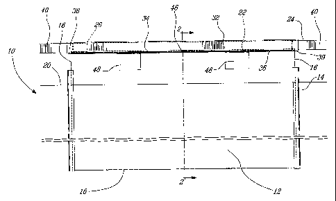
(017] Referring to Figure 2, the upper edge 22 of the deposition plate 12
is attached to a copper hanger bar 24 by first inserting the deposition
plate 12 into a slot 26 machined in the lower surface 28 of the copper
hanger bar 24. The deposition plate 12 is then welded to the copper
hanger bar 24 using known TIG welding techniques. In this manner a first
pair of seam welds as in 30 are formed on both surfaces and along the
entire breadth of the deposition plate 12 at the point where the surfaces of
the deposition plate 12 meet the lower surface of the hanger bar 24.
(018] In an alternative embodiment the upper edge 22 of the deposition
plate is not inserted in a slot but rather butts against the lower surface 28
of the hanger bar 24.
(019] The hanger bar 24 is manufactured from an unalloyed solid copper
of a high purity, such as electrolytic tough pitch copper with the UNS
CA 02489889 2004-12-17
WO 03/106738 PCT/CA03/00919
7
(Unified Numbering System) designation 011000, and the first pair of
seam welds 30 serve primarily to provide for good conduction of electrical
current between the deposition plate 12 and the copper hanger bar 24.
[020 Referring back to Figure 1 in addition to Figure 2, the hanger bar
24, the upper edge 22 of the deposition plate 12 and the first pair of seam
welds 30 are encapsulated in an elongate stainless steel cladding 32, the
cladding 32 manufactured from an AISI type 316 stainless steel sheet of
1.5 mm thickness. The cladding 32 is suitably formed and includes a
clearance fit such that it may be slid freely over the hanger bar/deposition
plate assembly following seam welding of the hanger bar 24 fio the
deposition plate 12.
[021 Once positioned over the hanger bar 24 and deposition plate 12,
the lower edges 34 of the cladding 32 are welded onto the surfaces of the
deposition plate 12. The welding results in the deposition of a second pair
of seam welds 36 along the entire breadth of the deposition plate 12
immediately below the first pair of seam welds 30. The cladding 32 and
second pair of seam welds 36 provide the dual purpose of re-enforcing
the hanger bar 24 as well as providing some protection against the
ingress of corrosive electrolyte solution and other liquids onto the first
pair
of seam welds 30 and into the joint between the upper edge 22 of the
deposition plate 12 and the lower surface 28 of the hanger bar 24.
Additionally, the lower edges towards the ends 38 of the cladding 32 are
joined and welded together.
(022] Referring to Figure 1, as stated above, during the electro-refining
process the deposition plate 12 is dipped in the electrolyte bath (not
shown) up to an approximate level indicated by the numeral 20. The
deposition plate is supported at this level by the ends 40 of the copper
hanger bar 24 which rest on a pair of electrically conductive bus bars
CA 02489889 2004-12-17
WO 03/106738 PCT/CA03/00919
8
running in parallel along opposite edges of the tank (all not shown)
containing the electrolyte bath. As a considerable mass of metal can be
deposited on the deposition plate 12 during the electro-refining process
(up to 200kg or more on a 1 m square sheet), a considerable force can be
brought to bear on the joint between the deposition plate 12 and the
copper hanger bar 24. The re-enforcement alleviates much of the stress
which would otherwise be exerted on the first pair of seam welds 30 by
the mass of deposited metal, thereby reducing the possibility that the first
pair of seam welds 30 are broken or otherwise cracked, thereby reducing
conductivity. This in turn improves the robustness and reliability of the
cathode assembly 10 and as a result its useful life.
[023] Referring back to Figure 2 in addition to Figure 1, although once
welded into place the cladding 32 provides some protection against the
ingress of corrosive electrolyte solution onto the first pair of seam welds
36, the seal provided by the second pair of seam welds 36 is not
hermetic. Therefore, if left unchecked the potential exists that corrosive
electrolyte solution or other liquids will eventually penetrate the second
pair of seam welds and detrimentally effect the join between hanger bar
24 and the deposition plate 12. This problem is exacerbated by the
unavoidable wear and tear which arises from the repeated insertion and
extraction of the cathode assembly 10 from the electrolyte bath (not
shown) as well as the removal of refined metals from the deposition plate
12 and the washing and refinishing of the surfaces of the deposition plate
12 prior to its reinsertion into the electrolyte bath. Therefore, to provide
additional protection against the ingress of corrosive solution or other
liquids beneath the cladding 32, a corrosion resistant sealant 42, for
example an epoxy resin, is injected into a space created between the
lower surface 28 of the hanger bar 24 and the inside surface 44 of the
cladding 32. This insures that the electrical conductivity between the
copper hanger bar 24 and the deposition plate 12 provided for by the first
CA 02489889 2004-12-17
WO 03/106738 PCT/CA03/00919
9
pair of seam welds 30 is maintained throughout an extended period of
time.
[024] Typically, the corrosion resistant material 42 is injected by boring
small holes as in 46 in the protective cladding 32. The corrosion resistant
material 42 in a free flowing form is then injected into the space between
the lower surface of the copper hanger bar 24 and the inside surface 44
of the cladding 32 along the entire length of the cladding 32. The
corrosion resistant material 42 then hardens forming a hermetic seal
around the first pair of seam welds 30.
[025] Referring now to Figure 1, as stated above during the refining
process a considerable mass of metal can be deposited on the deposition
plate 12. Therefore, in order to assist in the automated extraction of the
cathode assembly 10 from the electrolyte tank (not shown) a pair of
rectangular slots as in 48 are machined through the deposition plate 12 at
a point immediately below the second pair of seam welds 36. Hooks (not
shown) or other lifting devices, such as the tines of a fork lift, can be
inserted in the slots 48 and the cathode assembly raised.
[026] Although the present invention has been described hereinabove by
way of a preferred embodiment thereof, this embodiment can be modified
at will, within the scope of the present invention, without departing from
the spirit and nature of the subject of the present invention.