Note: Descriptions are shown in the official language in which they were submitted.
CA 02490448 2004-12-21
WO 2004/004038 PCT/JP2003/008099
-1-
DESCRIPTION
FUEL CELL AND FUEL CELL STACK
Technical Field
The present invention relates to a fuel cell having
circular disk-shaped electrolyte electrode assemblies
interposed between separators. Each of the electrolyte
electrode assemblies includes an anode, and a cathode, and
an electrolyte interposed between the anode and the cathode.
Further, the present invention also relates to a fuel cell
stack formed by stacking a plurality of such fuel cells.
Background Art
Typically, a solid oxide fuel cell (SOFC) employs an
electrolyte of ion-conductive solid oxide such as stabilized
zirconia. The electrolyte is interposed between an anode
and a cathode to form an electrolyte electrode assembly.
The electrolyte electrode assembly is interposed between
separators (bipolar plates), and the electrolyte electrode
assembly and the separators make up a unit of fuel cell for
generating electricity. A predetermined number of fuel
cells are stacked together to form a fuel cell stack.
In the fuel cell, an oxygen-containing gas or air is
supplied to the cathode. The oxygen in the oxygen-
containing gas is ionized at the interface between the anode
and the electrolyte, and the oxygen ions (Oz-) move toward
the anode through the electrolyte. A fuel gas such as
CA 02490448 2004-12-21
WO 2004/004038 PCT/JP2003/008099
-2-
hydrogen-containing gas or CO is supplied to the anode.
Oxygen ions react with the hydrogen in the hydrogen-
containing gas to produce Ha0 or react with CO to produce
CO2. Electrons released in the reaction flow through an
external circuit to the cathode, creating a DC electric
current.
Generally, the solid oxide fuel cell is operated at a
high temperature in the range from 800°C to 1000°C. The
solid oxide fuel cell utilizes the high temperature waste
heat for internal reforming to produce the fuel gas, and
generates electricity by spinning a gas turbine. The solid
oxide fuel cell is attractive as it has the highest
efficiency in generating electricity in comparison with
other types of fuel cells, and receiving growing attention
for potential use in vehicles in addition to the
applications in combination with the gas turbine.
Stabilized zironia has a low ion conductivity.
Therefore, the electrolyte membrane formed of stabilized
zirconia weeds to be thin so that oxygen ions move through
the electrolyte membrane smoothly for improving the power
generation performance. However, the electrolyte membrane
of the stabilized zirconia can not be very thin for
maintaining the sufficient mechanical strength. Therefore,
it is difficult to produce a large electricity using the
membrane of stabilized zirconia in the solid oxide fuel
cell.
In an attempt to address the problem, Japanese Laid-
CA 02490448 2004-12-21
WO 2004/004038 PCT/JP2003/008099
-3-
Open Patent Publication No. 5-266910 (prior art 1) discloses
a solid oxide fuel cell system in which a plurality of cells
are disposed on one surface (area) between adjacent
separators. In the prior art 1, the plurality of cells are
5. provided between the separators to increase the total
surface area of the cells for generating a large current,
while preventing damages to the electrolyte plate to improve
the reliability of the fuel cell system.
FIG. 25 is a perspective view showing the fuel cell
system disclosed in the prior art 1. As shown in FIG. 25,
the fuel cell system includes a plurality of layers stacked
together to form a stack body. Each of the layers includes
a separator 1 and four cells 2 placed on the separator 1. A
fuel gas plate 3 on the lowermost layer has supply ports and
discharge ports for supplying and discharging a fuel gas.
An oxygen-containing gas plate 4 on the uppermost layer has
supply ports and discharge ports for supplying and
discharging an oxygen-containing gas.
Fuel gas supply manifolds 5a, 5b extend through the
separators 1 for supplying the fuel gas to each of the cells
2, and fuel gas discharge manifolds 5c, 5d extend through
the separators 1 for discharging the fuel gas from each of
the cells 2 after reaction.' Further, oxygen-containing gas
supply manifolds 5a, 5b extend through the separators 1 for
supplying the oxygen-containing gas to each of the cells 2,
and oxygen-containing gas discharge manifolds 5c, 5d extend
through the separators 1 for discharging the oxygen-
CA 02490448 2004-12-21
WO 2004/004038 PCT/JP2003/008099
-4-
containing gas from each of the cells 2 after reaction.
The fuel gas supply manifolds 5a, 5b are connected to
fuel gas supply pipes 7a, 7b at the fuel gas plate 3. The
fuel gas discharge manifolds 5c, 5d are connected to fuel
gas discharge pipes 7c, 7d at the fuel gas plate 3. The
oxygen-containing gas supply manifolds 6a, 6b are connected
to oxygen-containing gas supply pipes 8a, 8b at the oxygen-
containing gas plate 4. The oxygen-containing gas discharge
manifolds 6c, 6d are connected to oxygen-containing gas
discharge pipes 8c, 8d at the oxygen-containing gas plate 4.
For example, .in the fuel gas plate 3 of the fuel cell
system, the fuel gas supplied to the fuel gas supply pipes
7a, 7b flows into the fuel gas supply manifolds 5a, 5b of
the separators 1 in the stacking direction and the fuel gas
is supplied to the anode of each cell 2. After the reaction
at the anode, the fuel gas flows back to the fuel gas plate
3 through the fuel gas discharge manifolds 5c, 5d, flows
into the fuel gas discharge pipes 7c, 7d, and is discharged
to the outside of the fuel cell system. In the oxygen-
containing gas plate 4, in the similar manner, the oxygen-
containing gas is supplied to, and discharged from the fuel
cell system through the oxygen-containing gas plate 4.
As described above, the fuel gas supplied to the fuel
gas plate 3 and the oxygen-containing gas supplied to the
oxygen-containing gas plate 4 flow through the separators 1,
and supplied to four cells 2 on each of the separators 1.
Therefore, the sealing structures for preventing the leakage
CA 02490448 2004-12-21
WO 2004/004038 PCT/JP2003/008099
-5-
of the reactant gases (fuel gas and oxygen-containing gas)
are required for the separators 1 (one sealing structure is
needed for every four cells 2). The sealing structures are
considerably complicated a.n the fuel cell system.
The fuel gas plate 3 is connected to the fuel gas
supply pipes 7a, 7b, and the fuel gas discharge pipes 7c,
7d. The oxygen-containing gas plate is connected to the
oxygen-containing gas supply pipes 8a, 8b, and the oxygen-
containing gas discharge pipes 8c, 8d. Therefore, the
overall fuel cell system is considerably large.
Further, Japanese Laid-Open Patent Publication No. 6-
310164 (prior art 2) discloses another type of solid oxide
fuel cell. In the solid oxide fuel cell, a plurality of
unit cells each having a small surface area are provided on
each of metallic separators, and a fuel gas supply hole and
an oxygen-containing gas supply hole are formed centrally in
each of the unit cells. The prior art 2 is directed to
provide a fuel cell system having an improved reliability in
which the total surface area of the cells on the separator
is large, and the substrate is crack-free.
However, in the prior art 2, the unit cells may not be
positioned at predetermined positions accurately. The fuel
gas supply hole and the oxygen-containing gas supply hole
provided centrally in each of the unit cells need to be
accurately in alignment with a fuel gas supply manifold and
an oxygen-containing gas supply manifold of the separator.
The positioning operation is very difficult. Thus, the
CA 02490448 2004-12-21
WO 2004/004038 PCT/JP2003/008099
-6-
assembling operation of the fuel cell is laborious, and the
production efficiency of the fuel cell is low.
Japanese Laid-Open Patent Publication No. 7-122287
(prior art 3) discloses an inside manifold system sheet type
solid oxide fuel cell module. Gas separating plates are
disposed at the upper end and lower end of a fuel cell
stack. A plate made of the same material as that of the gas
separating plates is provided outside of at least one of the
gas separating plates. An insulative side surface
supporting member for supporting side surface supporting
member for supporting side surfaces of the fuel cell stack
extends for each side surface of the cell stack. One end of
the insulative side surface supporting member is joined to
the plate.
However, the prior art 3 is directed to the prevention
of misalignment of the cells and separating plates in the
horizontal direction. Therefore, the prior art 3 does not
enable plurality of cells to be positioned accurately on the
separator surface.
Disclosure of Invention
A general object of the present invention is to
provide a fuel cell and a fuel cell stack having a compact
and simple structure, while maintaining the desired power
generation performance.
Further, a main object of the present invention is to
provide a fuel cell and fuel cell stack in which a plurality
CA 02490448 2004-12-21
WO 2004/004038 PCT/JP2003/008099
of electrolyte electrode assemblies are arranged, and the
positioning operation of the electrolyte electrode
assemblies is easily carried out, while maintaining the
desired power generation performance.
According to the present invention, the electrolyte
electrode assemblies may be arranged along at least one
virtual circle concentric with a central axis of the
separators. Thus, a large number of the electrolyte
electrode assemblies are arranged between the separators.
With the compact structure, the fuel cell has a high power
outputting performance. Even if some of the electrolyte
electrode assemblies have power failures, the fuel cell
stack can be energized by the other electrolyte electrode
assemblies. Therefore, the power generation can be
performed reliably.
Further, each of the separators may include a
plurality of plates which are stacked together. A fuel gas
supply channel for supplying a fuel gas to the anode, and an
oxygen-containing gas supply channel for supplying an
oxygen-containing gas to the cathode may be provided between
the plates. Since the fuel gas channel and the oxygen-
containing gas channel are formed inside the separator, the
sealing structure is simple in comparison with the structure
in which the reactant gas channels (fuel gas channel and the
oxygen-containing gas channel) extend in the stacking
direction. With the simple structure, the desired sealing
performance can be reliably maintained. Further, the
CA 02490448 2004-12-21
WO 2004/004038 PCT/JP2003/008099
_8_
overall size of the fuel cell is compact, and the power
collecting efficiency is improved easily.
The electrolyte electrode assemblies are compact and
thin. The temperature distribution on the electrode surface
is uniform. In particular, when solid oxide is used,
damages to the solid oxide due to heat stress are prevented,
and the resistance polarization is reduced. Thus, the power
outputting performance is improved.
According to the present invention, the electrolyte
electrode assemblies may be arranged along at least two
virtual circles concentric with a central axis of the
separators. Therefore, a large number of the electrolyte
electrode assemblies are arranged between the separators.
With the compact structure, the fuel cell has a high power
outputting performance. The electrolyte electrode
assemblies are compact and thin. The temperature
distribution on the electrode surface is uniform.
According to the present invention, inner electrolyte
electrode assemblies may be out of radial alignment with
outer electrolyte electrode assemblies. Therefore, the
electrolyte electrode assemblies are arranged densely. With
the compact structure of the fuel cell, the desired power
generation performance is maintained. The fuel gas and the
oxygen-containing gas after the reaction (exhaust gas) do
not impinge on the inner electrolyte electrode assemblies.
Therefore, turbulence does not occur, and the exhaust gas is
smoothly guided to the exhaust gas hole.
CA 02490448 2004-12-21
WO 2004/004038 PCT/JP2003/008099
-9-
According to the present invention, the inner
electrolyte electrode assemblies and the outer electrolyte
electrode assemblies may be arranged alternately.
Therefore, the electrolyte electrode assemblies are arranged
densely, and the fuel cell is compact.
According to the present invention, the fuel gas and
the oxygen-containing gas may be supplied through the fuel
gas channel and the oxygen-containing gas channel to central
regions on opposite surfaces of the electrolyte electrode
assemblies, respectively. The fuel gas and the oxygen-
containing gas may flow, outwardly from the central regions
of the electrolyte electrode assemblies. Thus, the
temperature distribution in the respective electrolyte
electrode assemblies is small, damages due to heat stress
are prevented, and the chemical reaction is uniformly
performed on the entire power generation surfaces.
The flow rate of the fuel gas supplied to the
electrolyte electrode assemblies is uniform, and the power
utilization ratio of the fuel gas is improved. The entire
surface area of the power generation surfaces is used
efficiently, and the power generation performance is
improved. The fuel gas and the oxygen-containing as are
supplied to opposite surfaces of the electrolyte electrode
assemblies. The fuel gas and the oxygen-containing gas flow
radially outwardly from the central regions on the opposite
surfaces of the electrolyte electrode assemblies. Thus, no
sealing structure for the fuel gas and the oxygen-containing
CA 02490448 2004-12-21
WO 2004/004038 PCT/JP2003/008099
-10
gas is required between the electrolyte electrode assemblies
and the separators, and the fuel cell has a simple
structure.
According to the present invention, the fuel gas
channel and the oxygen-containing gas channel may be
provided between two of the plates of the separator. Thus,
the layout of the fuel cell stack is simple, and the
thickness of the fuel cell stack in the stacking direction
is small.
According to the present invention, the discharge
passage for discharging the fuel gas and the oxygen-
containing gas after reaction may be provided between the
separators. Manifolds for supplying and discharging the
oxygen-containing gas and the fuel gas can be formed by the
separators without any special components. Thus, the fuel
cell stack has a simple structure.
According to the present invention, a circular hole
for discharging the exhaust gas may be formed at the central
region of the separators. The electrolyte electrode
assemblies may have circular disk shape. The electrolyte
electrode assemblies may be arranged along at least one
virtual circle concentric with the circular hole.
Therefore, the sealing structure around the circular hole is
simple. The exhaust gas simply flows toward the circular
hole at the central region of the separators. Thus, the
flow rate of the exhaust gas is uniform, and the exhaust gas
is discharged from the electrolyte electrode assemblies
CA 02490448 2004-12-21
WO 2004/004038 PCT/JP2003/008099
-11-
smoothly.
According to the present invention, the electrolyte
electrode assemblies may be arranged around the circular
hole, along at least two virtual circles concentric with the
circular hole. Thus, the electrolyte electrode assemblies
are arranged densely, and the overall fuel cell is compact.
The fuel cell has a high outputting performance, and the
separators have a light weight.
According to the present invention, a plurality of
circular disk-shaped electrolyte electrode assemblies may be
arranged along at least one virtual circle concentric with a
central axis of disk-shaped separators.
Each of the end plates may have holes for inserting
bolts to tighten the fuel cell stack, and the holes and the
electrolyte electrode assemblies may be arranged
alternately. Therefore, the outer dimensions of the overall
fuel cell stack are small, and the fuel cell stack is
compact.
According to the present invention, at least one of
the plates may have protrusions for positioning the
electrolyte electrode assemblies between the separators.
Therefore, the electrolyte electrode assemblies are
positioned accurately and easily. The positions of the
electrolyte electrode assemblies do not change due to
thermal history or the like. The assembling operation of
the fuel cell is efficiently performed, and the power
generation performance in the respective fuel cells is
CA 02490448 2004-12-21
WO 2004/004038 PCT/JP2003/008099
-12-
greatly improved.
According to the present invention, the protrusions
may be provided so that the electrolyte electrode assemblies
are arranged along at least one virtual circle concentric
with a central axis of the separators. Therefore, many
electrolyte electrode assemblies are arranged densely
between the separators. Thus, the electricity produced in
the fuel cell per unit volume is increased. With the
compact structure, the fuel cell has a high power outputting
performance.
Even if some of the electrolyte electrode assemblies
have power failures, the fuel cell stack can be energized by
the other electrolyte electrode assemblies. Therefore, the
power generation can be performed reliably.
According to the present invention, inner electrolyte
electrode assemblies may be out of radial alignment with
outer electrolyte electrode assemblies. Therefore, the
electrolyte electrode assemblies are arranged densely. With
the compact structure of the fuel cell, the desired power
generation performance is maintained.
According to the present invention, at least three
protrusions may be provided for positioning each of the
electrolyte electrode assemblies inside the three
protrusions with a clearance. The assembling operation of
the electrolyte electrode assemblies can be performed simply
by placing the electrolyte electrode assemblies inside the
protrusions. Further, even if the electrolyte electrode
CA 02490448 2004-12-21
WO 2004/004038 PCT/JP2003/008099
-13-
assemblies are thermally expanded, the electrolyte electrode
assemblies are not damaged.
According to the present invention, each of the disk
shaped separators may have protrusions for positioning the
electrolyte electrode assemblies between the separators.
The electrolyte electrode assemblies may be arranged along
at least one virtual circle concentric with a central axis
of the separators. Each of the flanges may have holes for
inserting bolts to tighten the fuel cell stack. The holes
and the electrolyte electrode assemblies may be arranged
alternately. Therefore, the outer dimensions of the overall
fuel cell stack are small, and the fuel cell stack is
compact.
According to the present invention, at least three
protrusions may be provided for positioning each of the
electrolyte electrode assemblies inside the protrusions with
a clearance. Therefore, the fuel cell can be assembled very
simply, and damages to the electrolyte electrode assemblies
due to thermal history or the like are effectively
prevented.
The above and other objects, features and advantages
of the present invention will become more apparent from the
following description when taken in conjunction with the
accompanying drawings in which preferred embodiments of the
present invention are shown by way of illustrative example.
Brief Description of Drawings
CA 02490448 2004-12-21
WO 2004/004038 PCT/JP2003/008099
_14_
FIG. 1 is a perspective view schematically showing a
fuel cell stack formed by stacking a plurality of fuel cells
according to a first embodiment of the present invention;
FIG. 2 is a cross sectional view showing a part of the
fuel cell stack;
FIG. 3 is a view schematically showing a gas turbine
including the fuel cell stack;
FIG. 4 is an exploded perspective view of the fuel
cell;
FIG. 5 is a perspective view showing a part of the
fuel cell and operation of the fuel cell;
FIG. 6 is a cross sectional view, with partial
omissions, showing the fuel cell stack;
FIG. 7 is an exploded perspective view showing a
separator of the fuel cell;
FIG. 8 is a front view showing a plate of the
separator;
FIG. 9 is a front view showing the other plate of the
separator;
FIG. 10 is a view showing operation of the fuel cell;
FIG. 11 is a view schematically showing a fuel cell
stack formed by stacking a plurality of fuel cells according
to a second embodiment of the present invention;
FIG. 12 is a cross sectional view showing a part of
the fuel cell stack;
FIG. 13 is a view schematically showing a gas turbine
including a plurality of the fuel cell stacks;
CA 02490448 2004-12-21
WO 2004/004038 PCT/JP2003/008099
-15-
FIG. 14 is a front view showing the gas turbine;
FIG. 15 is an exploded perspective view of the fuel
cell;
FIG. 16 is a perspective view showing a part of the
fuel cell and operation of the fuel cell;
FIG. 17 is a cross sectional view, with partial
omissions, showing the fuel cell stack taken along a line
XVII-XVII of FIG. 16;
FIG. 18 is an exploded perspective view showing a
separator of the fuel cell;
FIG. 19 is an enlarged view showing a part of the fuel
cell;
FIG. 20 is a front view showing a plate of the
separator;
FIG. 21 is a front view showing the other plate of the
separator;
FIG. 22 is a view~showing operation of the fuel cell;
FIG. 23 is a cross sectional view schematically
showing a gas turbine including relatively large fuel cell
stacks according to a third embodiment of the present
invention;
FIG. 24 is a front view showing the gas turbine; and
FIG. 25 is an exploded perspective view showing a
conventional fuel cell system.
Best Mode for Carrying Out the Invention
FIG. 1 is a perspective view schematically showing a
CA 02490448 2004-12-21
WO 2004/004038 PCT/JP2003/008099
-16-
fuel cell stack 12 formed by stacking a plurality of fuel
cells 10 according to a first embodiment of the present
invention, and FIG. 2 is a cross sectional view showing a
part of the fuel cell stack 12.
The fuel cell 10 is a solid oxide fuel cell (SOFC) for
stationary and mobile applications. For example, the fuel
cell 10 is mounted on vehicles. In an example of the first
embodiment shown in FIG. 3, the fuel cell stack 12 is used
in a gas turbine 14. In FIG. 3, the shape of the fuel cell
stack 12 is different from those shown in FIGS. 1 and 2,
however, the structure i.s substantially the same. The fuel
cell stack 12 is disposed in a casing 16 of the gas turbine
14. A combustor 18 is disposed at the center of the fuel
cell stack 12. The fuel cell stack 12 discharges an exhaust
gas as a mixed gas of a fuel gas and an oxygen-containing
gas after reaction into a chamber 20 toward the combustor
18. The chamber 20 is narrowed in a flowing direction of
the exhaust gas indicated by an arrow X. A heat exchanger
22 is externally provided around the chamber 20 at a forward
end in the flowing direction. Further, a turbine (power
turbine) 24 is disposed at the forward end of the chamber
20. A compressor 26 and a power generator 28 are coaxially
connected to the turbine 24. The gas turbine 14 has an
axially symmetrical structure as a whole.
A discharge passage 30 of the turbine 24 is connected
to a first passage 32 of the heat exchanger 22. A supply
passage 34 of the compressor 26 is connected to a second
CA 02490448 2004-12-21
WO 2004/004038 PCT/JP2003/008099
-17-
passage 36 of the heat exchanger 22. The air is supplied to
the outer circumferential surface of the fuel cell stack 12
through a hot air inlet passage 38 connected to the second
passage 36.
'5 As shown in FIG. 1, the fuel cell stack 12 is formed
by stacking a plurality of fuel cells 10 in a stacking
direction indicated by an arrow A. Each of the fuel cells
has a shape of a disk having a curved outer section. End
plates (flanges) 40a, 40b are provided outside the outermost
10 fuel cells 10 at opposite ends in the stacking direction,
respectively. The fuel cells 10 and the end plates 40a, 40b
are tightened together by a plurality of (e. g., eight)
tightening bolts 42. At the center of the fuel cell stack
12, a circular hole 44 is formed for discharging the exhaust
gas from the fuel cell stack 12. The circular hole 44 has a
bottom at the end plate 40b, and extends in the direction
indicated by the arrow A (see FIG. 2).
A plurality of (e. g., four) fuel gas supply passages
46 are formed along a virtual circle concentric with the
circular hole 44. Each of the fuel gas supply passages 46
has a bottom at the end plate 40a, and extend from the end
plate 40b in the direction indicated by the arrow A. The
end plates 40a, 40b have output terminals 48a, 48b,
respectively.
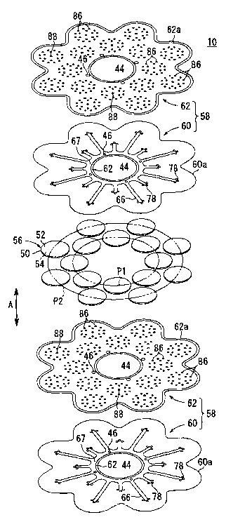
As shown in FIGS. 4 and 5, the fuel cell 10 includes
electrolyte electrode assemblies 56. Each of the
electrolyte electrode assemblies 56 includes a cathode 52,
CA 02490448 2004-12-21
WO 2004/004038 PCT/JP2003/008099
-18-
an anode 54, and an electrolyte (electrolyte plate) 50
interposed between the cathode 52 and the anode 54. The
electrolyte 50 is formed of an ion-conductive solid oxide
such as stabilized zirconia. The electrolyte electrode
assembly 56 has a relatively small circular disk shape.
A plurality of (e. g., 16) the electrolyte electrode
assemblies 56 are interposed between a pair of separators 58
to form the fuel cell 10. The electrolyte electrode
assemblies 56 are arranged along an inner circle P1 and an
outer circle P2 which are concentric with the circular hole
44 formed at the center of the separators 58. The inner
circle P1 passes through centers of eight inner electrolyte
electrode assemblies 56, and the outer circle P2 passes
through centers of eight outer electrolyte electrode
assemblies 58 (see FIG. 4).
Each of the separators 58 includes a plurality of
(e. g., two) plates 60, 62 which are stacked together. Each
of the plates 60, 62 is formed of a stainless alloy, for
example. Curved sections 60a, 62a are formed on the plates
60, 62, respectively.
As shown in FIGS. 6 through 8,, the plate 60 has an
inner ridge 64 formed around the circular hole 44. The
inner ridge 64 protrudes toward the plate 62. Further, the
plate 60 has a protrusion 65 around the fuel gas supply
passages 46. The protrusion 65 protrudes away from the
plate 62. Further, the plate 60 has an outer ridge 66
formed concentrically with the inner ridge 64. A fuel gas
CA 02490448 2004-12-21
WO 2004/004038 PCT/JP2003/008099
-19-
channel 67 connected to the fuel gas supply passages 46 a.s
formed between the inner ridge 64 and the outer ridge 66.
The outer ridge 66 includes first walls 68 and second
walls 70 each extending radially outwardly by a
predetermined distance. The first walls 68 and the second
walls 70 are formed alternately. As shown in FIG. 8, each
of the first walls 68 extends to the inner circle P1 which
is a virtual line passing through centers of the eight inner
electrolyte electrode assemblies 56. The first walls 68 are
connected to the second walls 70. Each of the second walls
70 extends to the outer circle P2 which is a virtual line
passing through the centers of the eight outer electrolyte
electrode assemblies 56.
At each end portion of the first walls 68 and at each
end portion of the second walls 70, three oxygen-containing
gas inlets 78 are formed. The oxygen-containing gas inlets
78 are formed to pass through the surface of the plate 60.
A first bosses 80 are formed on the plate 60. The first
bosses 80 protrude toward, and contact the electrolyte
electrode assemblies 56 arranged along the first circle P1
and the second circle P2.
A fuel gas channel 67 is formed inside the inner ridge
64 and the outer ridge 66 between the plate 60 and the plate
62. Further, an oxygen-containing gas channel 82 is formed
outside the outer ridge 66. The oxygen-containing gas
channel 82 is connected to the oxygen-containing gas inlets
78 on the plate 60.
CA 02490448 2004-12-21
WO 2004/004038 PCT/JP2003/008099
-20-
As shown in FIGS. 6, 7, and 9, the plate 62 has
protrusions 84 around the respective fuel gas supply
passages 46. The protrusions 84 protrude away from the
plate 60. Further, the plate 62 has second bosses 86
protruding toward, and contact the electrolyte electrode
assemblies 56 arranged along the inner circle P1 and the
outer circle P2. The second bosses 86 have small dimensions
(height and diameter) in comparison with the first bosses
80. Fuel gas inlets 88 are formed to pass through the plate
62 to the inside of the end portions of the first wall 68
and the second wall 70, respectively.
The separator 58 has insulator seals 90 for sealing
the fuel gas supply passages 46 (see FIG. 6). For example,
the insulator seal 90 is formed by placing a ceramics plate
on the plate 60 or the plate 62 or forming the insulator
seal 90 on the plate 60 or the plate 62 by thermal spraying.
The curved outer sections 60a, 62a protrude away from each
other. An insulator seal 92 is provided on the curved outer
section 60a or the curved outer section 62a by inserting the
insulator seal 92 between the curved outer section 60a and
the curved outer section 62a. Alternatively, the insulator
seal 92 of ceramics or the like is formed on the curved
outer section 60a or the curved outer section 62a by thermal
spraying.
As shown in FIGS. 5 and 6, the electrolyte electrode
assemblies 56 are interposed between the plate 60 of one
separator 58 and the plate 62 of the other separator 58.
CA 02490448 2004-12-21
WO 2004/004038 PCT/JP2003/008099
-21-
Specifically, the plate 60 and the plate 62 outside the
electrolyte electrode assemblies 56 has the first bosses 80
and the second bosses 86 protruding toward the electrolyte
electrode assemblies 56 for sandwiching the electrolyte
electrode assemblies 56.
As shown in FIG. 10, a fuel gas flow passage 94
connected to the fuel gas channel 67 through the fuel gas
inlets 88 is formed between the electrolyte electrode
assemblies 56 and the plate 62 of the separator 58.
Further, an oxygen-containing gas flow passage 96 connected
to the oxygen-containing gas channel 82 through the oxygen-
containing gas inlets 78 is formed between the electrolyte
electrode assemblies 56 and the plate 60 of the other
separator 58 on the opposite side. The size of the opening
of the fuel gas flow passage 94 depends on the height of the
second bosses 86. The size of the opening of the oxygen-
containing gas flow passage 96 depends on the height of the
first bosses 80. The flow rate of the fuel gas is smaller
than the flow rate of the oxygen-containing gas. Therefore,
the dimensions of the second bosses 86 are smaller than the
dimensions of the first bosses 80.
As shown in FIG. 6, the fuel gas channel 67 formed
between the plates 60, 62 of the separator 58 is connected
to the fuel gas supply passages 46. The oxygen-containing
gas channel 82 and the fuel gas channel 67 are formed on the
same area inside the separator. The oxygen-containing gas
channel 82 is open to the outside through the spacing
CA 02490448 2004-12-21
WO 2004/004038 PCT/JP2003/008099
-22
between the curved outer sections 60a, 62a of the plates 60,
62 of the separator 58.
Each of the separators 58 stacked in the stacking
direction has the first bosses 80 and the second bosses 86
for sandwiching the electrolyte electrode assemblies 56.
The first bosses 80 and the second bosses 86 function as
current collectors. The outer ridge 66 of the plate 60 is
in contact with the plate 62 for serially connecting the
fuel cells 10 in the direction indicated by the arrow A.
As shown in FIGS. 1 and 2, the fuel cells 10 are
stacked in the direction indicated by the arrow A. End
plates 40a, 40b are disposed outside the outermost fuel
cells 10 at opposite ends. The end plates 40a, 40b has
holes 100a, 100b at positions corresponding to the inward
curves of the curved outer sections 60a, 62a of the plates
60, 62. Insulator members 102a, 102b are attached in the
holes 100a, 100b. The tightening bolts 42 are inserted in
the insulator members 102a, 102b. Ends of the tightening
bolts 42 are screwed into nuts 104 for tightening the fuel
cells 10 together with a suitable force.
Next, operation of the fuel cell stack 12 will be
described below.
In assembling the fuel cell 10, the plate 60 and the
plate 62 are connected together to form the separator 58.
Specifically, as shown in FIG. 6, the outer ridge 66
extending integrally from the plate 60 are connected to the
plate 62 by brazing, and the ring-shaped insulator seals 90
CA 02490448 2004-12-21
WO 2004/004038 PCT/JP2003/008099
-23-
are provided on the plate 60 or the plate 62 around the fuel
gas supply passages 46 by thermal spraying, for example.
Further, the insulator seal 92 having curves is provided on
the curved outer section 60a of the plate 60 or the curved
outer section 62a of the plate 62 by thermal spraying, for
example.
The separator 58 thus formed has the fuel gas channel
67 and the oxygen-containing gas channel 82 on the same area
between the plate 60 and the plate 62. The fuel gas channel
67 is connected to the fuel gas supply passages 46, and the
oxygen-containing gas channel 82 between the curved outer
section 60a and the curved outer section 62a is open to the
outside.
Then, the electrolyte electrode assemblies 56 are
interposed between a pair of separators 58. As shown in
FIGS. 4 and 5, sixteen electrolyte electrode assemblies 56
are interposed between the plate 60 of one separator 58 and
the plate 62 of the other separator 58. Eight electrolyte
electrode assemblies 56 are arranged along the inner circle
P1, and eight electrolyte electrode assemblies 56 are
arranged along the outer circle P2. The first bosses 80 of
the plate 60 and the second bosses 86 of the plate 62
protrude toward, and contact the electrolyte electrode
assemblies 56.
As shown in FIG. 10, the oxygen-containing gas flow
passage 96 is formed between the cathodes 52 of the
electrolyte electrode assemblies 56 and the plate 60. The
CA 02490448 2004-12-21
WO 2004/004038 PCT/JP2003/008099
-24-
oxygen-containing gas flow passage 96 is connected to the
oxygen-containing gas channel 82 through the oxygen-
containing gas inlets 78. The fuel gas flow passage 94 is
formed between the anodes 54 of the electrolyte electrode
assemblies 56 and the plate 62. The fuel gas flow passage
94 is connected to the fuel gas channel 67 through the fuel
gas inlets 88. An exhaust gas passage 106 is formed between
the separators 58 for guiding the exhaust gas (mixed gas of
the fuel gas and the oxygen-containing gas after reaction)
to the circular hole 44.
A plurality of the fuel cells 10 as assembled above
are stacked in the direction indicated by the arrow A to
form the fuel cell stack 12 (see FIGS. 1 and 2).
The fuel gas such as a hydrogen containing gas is
supplied to the fuel gas supply passages 46 of the end plate
40b, and the oxygen-containing gas such as air i.s supplied
from the outside of the fuel cells 10 under pressure. The
fuel gas supplied to the fuel gas supply passages 46 flows
in the stacking direction indicated by the arrow A, and is
supplied to the fuel gas channel 67 formed in each of the
separators 58 of the fuel cells 10 (see FIG. 6).
As shown in .FIG. 8, the fuel gas flows along the first
walls 68 and the second walls 70 of the outer ridge 66, and
flows into the fuel gas flow passage 94 (see FIG. 5). The
fuel gas inlets 88 are formed at end portions of the first
walls 68 and the second walls 70, i.e., at positions
corresponding to central regions of the anodes 54 of the
CA 02490448 2004-12-21
WO 2004/004038 PCT/JP2003/008099
-25-
electrolyte electrode assemblies 56. The fuel gas supplied
to the fuel gas flow passage 94 flows outwardly from the
central regions of the anodes 54 (see FIG. 10).
The oxygen-containing gas is supplied to each of the
fuel cells 10 from the outside. The oxygen-containing gas
is supplied to the oxygen-containing gas channel 82 formed
in each of the separators 58, between the plate 60 and the
plate 62. The oxygen-containing gas supplied to the oxygen-
containing gas channel 82 flows into the oxygen-containing
gas flow passage 96 from the oxygen-containing gas inlets
78, and flows outwardly from central regions of the cathodes
52 of the electrolyte electrode assemblies 56 (see FIGS. 5
and 10).
Therefore, in each of the electrolyte electrode
assemblies 56, the fuel gas is supplied to the central
region of the anode 54, and flows outwardly from the central
region of the anode 54. Similarly, the oxygen-containing
gas is supplied to the central region of the cathode 52, and
flows outwardly from the central region of the cathode 52.
The oxygen-ion passes from the cathode 52 to the anode 54
through the electrolyte 50 to generate electricity by
electrochemical reactions.
The electrolyte electrode assemblies 56 are sandwiched
between the first bosses 80 and the second bosses 86.
Therefore, the first bosses 80 and the second bosses 86
function as current collectors. The fuel cells 10 are
electrically connected in series in the stacking direction
CA 02490448 2004-12-21
WO 2004/004038 PCT/JP2003/008099
-26-
indicated by the arrow A. The electricity can be outputted
form the output terminals 48a, 48b. Even if some of the
electrolyte electrode assemblies 56 have power failures, the
fuel cell stack 12 can be energized by the other electrolyte
electrode assemblies 56. Therefore, the power generation
can be performed reliably.
After reaction of the fuel gas and the oxygen-
containing gas, the exhaust gas moves outwardly from the
central regions of the electrolyte electrode assemblies 56
through the exhaust passage 106 between the separators 58,
and flows toward the center of the separators 58. The
exhaust gas flows into the circular hole 44 formed at the
center of separators 58, and is discharged from the circular
hole 44 to the outside.
In the first embodiment, a plurality of (e.g., 16)
circular electrolyte electrode assemblies 56 having a
relatively small diameter are provided between a pair of
separators 58. Thus, the electrolyte electrode assemblies
56 can be thin, and the resistance polarization is reduced.
Further, temperature distribution is small, and damages due
to heat stress are prevented. Therefore, the power
generation performance of the fuel cells 10 is effectively
improved.
Further, the eight inner electrolyte electrode
assemblies 56 are arranged along the inner circle P1, and
the eight outer electrolyte electrode assemblies 56 are
arranged along the outer circle P2. The inner circle P1 and
CA 02490448 2004-12-21
WO 2004/004038 PCT/JP2003/008099
-27
the outer circle P2 are concentric with the circular hole 44
positioned at the center of the separators 58. The eight
outer eight electrolyte electrode assemblies 56 are
positioned out of radial alignment with the eight inner
electrolyte electrode assemblies 56. Stated otherwise, the
inner electrolyte electrode assemblies 56 and the outer
electrolyte electrode assemblies 56 are arranged alternately
along the inner circle P1 and the outer circle P2,
respectively.
The electrolyte electrode assemblies 56 can be
arranged between the separators 58 densely. Thus, the
overall fuel cell 10 can be made compact, while maintaining
the desired power generation performance. Additionally,
since the exhaust gas does not impinge on the inner
electrolyte electrode assemblies 56 arranged along the inner
circle P1, the turbulence of the exhaust gas does not occur,
and the exhaust gas is guided to the circular hole 44 at the
center of the separators 58. Since the exhaust gas from the
electrolyte electrode assemblies 56 is discharged into the
circular hole 44 without any turbulence, the flow rate of
the exhaust gas is kept constant. Thus, the pressure loss
in the fuel cell 10 is small, and the power generation
performance is improved.
Each of the separators 58 has the two plates 60, 62,
and the fuel gas channel 67 and the oxygen-containing gas
channel 82 are formed between the plates 60, 62. Thus, in
comparison with a structure in which reactant gas passages
CA 02490448 2004-12-21
WO 2004/004038 PCT/JP2003/008099
_~8_
extend in the stacking direction, the sealing structure of
the fuel cell 10 is greatly simplified. Thus, the reliable
sealing performance is achieved desirably. Further, the
overall size of the fuel cell 10 is reduced, and the
improvement of the power collecting efficiency is achieved
easily.
Further, in the first embodiment, the fuel gas flows
from the fuel gas channel 67 into the fuel gas inlets 88 and
the oxygen-containing gas flows from the oxygen-containing
gas channel 82 into the oxygen-containing gas inlets 78.
The fuel gas inlets 88 and the oxygen-containing gas inlets
78 are positioned at central regions on opposite surfaces of
the electrolyte electrode assemblies 56 (see FIG. 10). The
fuel gas and the oxygen-containing gas flow outwardly from
the central regions of the electrolyte electrode assemblies
56. Therefore, the temperature distribution in the
respective electrolyte electrode assemblies 56 is small, and
damages due to heat stress are prevented. The
electrochemical reaction is uniform on the entire power
generation surface.
In the structure, the flow rate of the fuel gas
supplied to each of the electrolyte electrode assemblies 56
is uniform. The utilization ratio of the fuel gas in the
electrolyte electrode assembly 56 is improved, and the
entire surface of the electrolyte electrode assembly 56 is
used efficiently. Thus, the power generation performance is
improved greatly.
CA 02490448 2004-12-21
WO 2004/004038 PCT/JP2003/008099
-29-
The fuel gas and the oxygen-containing gas are
supplied to the central regions on the opposite surfaces of
the electrolyte electrode assemblies 56. The fuel gas and
the oxygen-containing gas flow from the central regions on
the opposite surfaces of the electrolyte electrode
assemblies 56 radially outwardly. Thus, no sealing
structure for the fuel gas and the oxygen-containing gas is
required between the electrolyte electrode assemblies 56 and
the separators 58, and the fuel cell 10 has a simple
structure.
The fuel gas channel 67 and the oxygen-containing gas
channel 82 are formed on the same area inside the separator
58. Therefore, The layout in designing the structure of the
fuel cell stack 12 is simplified, and the thickness of the
fuel cell stack 12 in the stacking direction is reduced.
Further, the exhaust gas passage 106 for discharging
the exhaust gas is formed in an area different from the area
in which the fuel gas channel 67 and the oxygen-containing
gas 82 are formed. The exhaust gas passage 106 is formed
between the separators 58 (see FIG. 10). Thus, the
separators 58 form the manifold for supplying the fuel gas
and the oxygen-containing gas, and the manifold for
discharging the fuel gas and the oxygen-containing gas.
Thus, the fuel cell stack 12 can be constructed without the
need of special components.
Further, in the first embodiment, the plates 60, 62 of
the separator 58 has curved outer sections 60a, 62a. The
CA 02490448 2004-12-21
WO 2004/004038 PCT/JP2003/008099
-30-
plates 60, 62 are curved inwardly toward the circular hole
44 at positions between the electrolyte electrode assemblies
56 arranged along the outer circle P2. The inward curves of
the plates 60, 62 are formed for providing tightening bolts
42 (see FIG. 1). Thus, the outer dimensions of the over all
fuel cell stack 12 are effectively reduced, and the fuel
cell stack 12 is small.
The curved outer sections 60a, 62a function as inlets
for receiving the air having a relatively low temperature.
Therefore, the tightening bolts 42 are not heated
excessively, and the service life of the tightening bolts 42
is extended.
Next, the operation of the fuel cell stack 12 used in
the gas turbine 14 shown in FIG. 3 will be described
briefly.
As shown in FIG. 3, in starting the operation of the
gas turbine 14, the combustor 18 is energized to spin the
turbine 24, and energize the compressor 26 and the power
generator 28. The compressor 26 functions to guide the
external air into the supply passage 34. The air is
pressurized and heated to a predetermined temperature (e. g.,
200°C), and supplied to the second passage 36 of the heat
exchanger 22. A hot exhaust gas as a mixed gas of the fuel
gas and the oxygen-containing gas after reaction is supplied
to the first passage 32 of the heat exchanger 22 for heating
the air supplied to the second passage 36 of the heat
exchanger 22. The heated air flows through the hot air
CA 02490448 2004-12-21
WO 2004/004038 PCT/JP2003/008099
-31-
supply passage 38, and supplied to the fuel cells 10 of the
fuel cell stack 12 from the outside. Thus, the power
generation is performed by the fuel cells 10, and the
exhaust gas generated by the reaction of the fuel gas and
the oxygen-containing gas is discharged into the chamber 20
in the casing 16.
At this time, the temperature of the exhaust gas
discharged from the fuel cells (solid oxide fuel cells) 10
is high, in the range of 800°C to 1000°C. The exhaust gas
spins the turbine 24 for generating electricity by the power
generator 28. The exhaust air is supplied to the heat
exchanger 22 for heating the external air. Therefore, it is
not necessary to use the combustor 18 for spinning the
turbine 24.
The hot exhaust gas in the range of 800° C to 1000° C
can be used for internally reforming a fuel supplied to the
fuel cell stack 12. Therefore, various fuels such as
natural gas, butane, and gasoline can be used for the
internal reforming.
FIG. 11 is a view schematically showing a fuel cell
stack 112 formed by stacking a plurality of fuel cells 110
according to a second embodiment of the present invention.
FIG. 12 is a cross sectional view showing a part of the fuel
cell stack 112. The constituent elements that are identical
to those of the fuel cell stack 12 formed by stacking the
fuel cells 10 according to the first embodiment are labeled
with the same reference numeral, and description thereof is
CA 02490448 2004-12-21
WO 2004/004038 PCT/JP2003/008099
-32-
omitted.
In FIG. 13, a plurality of fuel cell stacks 112 are
placed in a gas turbine 114. As shown in FIG. 14, for
example, eight fuel cell stacks 112 are provided around a
combustor 18 at intervals of 45° in the casing 116. Each of
the fuel cell stacks 112 is covered by a cover 118 attached
to the casing 116. Pressurized air inlet passages 120 are
formed inside the respective covers 118. The exhaust gas
produced after reaction of the fuel gas and the oxygen-
containing gas is discharged from each central portion of
the fuel cell stacks 112.
As shown in FIG. 11, the fuel cell stack 112 is formed
by stacking a plurality of fuel cells 110 in the stacking
direction indicated by the arrow A. Each of the fuel cells
110 has a shape of a disk having a curved outer section.
End plates 147a, 147b are provided outside the outermost
fuel cells 110 at opposite ends in the stacking direction,
respectively. Insulator plates 148a, 148b are provided on
the outside the end plates 147a, 147b. Further, flanges
140a, 140b are provided on the outside of the insulator
plates 148a, 148b. The fuel cells 110, the end plates 147a,
147b, the insulator plates 148a, 148b, and the flanges 140a,
140b are tightened together by a plurality of (e. g., eight)
tightening bolts 42. At the center of the fuel cell stack
112, a circular fuel gas supply hole 146 is formed for
supplying the fuel gas to the fuel cell stack 112. The fuel
gas supply hole 146 has a bottom at the flange 140a, and
CA 02490448 2004-12-21
WO 2004/004038 PCT/JP2003/008099
-33-
extends in the stacking direction indicated by the arrow A
(see FIG. 12).
A plurality of (e.g., four) exhaust gas passages 144
are formed around the fuel gas supply hole 146. Each of the
exhaust gas passages 144 has a bottom at the flange 140b,
and extends in the direction indicated by the arrow A. The
flange 140a is insulated from the end plate 147a by the
insulator plate 148a, and the flange 140b is insulated from
the end plate 147b by the insulator plate 148. The end
plates 147a, 147b have output terminals 48a, 48b,
respectively.
As shown in FIGS. 15 and 16, a plurality of (e.g., 16)
electrolyte electrode assemblies 56 are interposed between a
pair of separators 158 to form the fuel cell 110. Each of
the separators 158 includes a plurality of (e. g., two)
plates 160, 162 which are stacked together. Each. of the
plates 160, 162 is formed of a stainless alloy, for example.
Curved outer sections 160a, 160b are formed on the plates
160, 162, respectively.
As shown in FIGS. 17, 18, and 20, ribs 163a are
provided around the center of the plate 160 to form the fuel
gas supply hole 146 and the four exhaust gas passages 144.
The plate 160 has four inner ridges 164a around the
respective exhaust gas passages 144. The inner ridges 164a
protrude toward the plate 162. The plate 160 has a
protrusion 165a around the fuel gas supply hole 146. The
protrusion 165a protrudes away from the plate 162.
CA 02490448 2004-12-21
WO 2004/004038 PCT/JP2003/008099
-34-
An outer ridge 166a is formed radially on the plate
160. A fuel gas channel 67 is formed inside the inner
ridges 164a and the outer ridge 166a. The fuel gas channel
67 is connected to the fuel gas supply hole 146.
The outer ridge 166a includes a plurality of first
walls 168a and second walls 170a each extending radially
outwardly by a predetermined distance. The first walls 168a
and the second walls 170a are formed alternately. As shown
in FIG. 20, each of the first walls 168a extends to an inner
circle P1 which is a virtual line passing through centers of
eight inner electrolyte electrode assemblies 56. Each of
the second walls 170a extends to an outer circle P2 which is
a virtual line passing through centers of eight outer
electrolyte electrode assemblies 56. The eight inner
electrolyte electrode assemblies 56 are arranged along the
inner circle P1, and the eight outer electrolyte electrode
assemblies 56 are arranged along the outer circle P2.
At each end portion of the first walls 168a and at
each end portion of the second walls 170a, three oxygen-
containing gas inlets 78 are formed. The oxygen-containing
gas inlets 78 are formed to pass through the plate 160.
First bosses 80 are formed on the plate 160. The first
bosses 80 protrude toward, and contact the electrolyte
electrode assemblies 56 arranged along the inner circle P1
and the outer circle P2.
As shown in FIGS. 17, 19, and 20, a first curved
protrusion 172a is formed on the plate 160 inside the curved
CA 02490448 2004-12-21
WO 2004/004038 PCT/JP2003/008099
-35-
outer section 160a. The first curved protrusion 172a has
the shape identical to the curved outer section 160a, and
protrudes away from the plate 162. Outer projections 174a
and inner projections 176a are provided at predetermined
intervals on opposite sides of the first curved protrusion
172a to face each other, or in a zigzag pattern.
As shown in FIGS. 17, 18, and 21, ribs 163b facing the
ribs 163a are provided around the center of the plate 162.
The plate 162 has four inner ridges 164b protruding toward
the plate 160, and a protrusion 165b protruding away form
the plate 160.
An outer ridge 166b protruding toward the outer ridge
166a of the plate 160 is formed on the plate 162. The inner
ridges 164a contact the inner ridges 164b, and the outer
ridge 166a contact the outer ridge 166b to form the fuel gas
channel 67 between the plate 160 and the plate 162. The
fuel gas channel 67 is connected to the fuel gas supply hole
146. The outer ridge 166b includes a plurality of first
walls 168b and second walls 170b each extending radially
outwardly by a predetermined distance. The first walls 168b
and the second walls 170b are formed alternately.
Protrusions 181 for positioning the eight electrolyte
electrode assemblies 56 along the inner circle P1 and the
eight electrolyte electrode assemblies 56 along the outer
circle P2 are provided on the plate 162. At least three
protrusions 181 are formed for each of the electrolyte
electrode assemblies 56. In the illustrated embodiment,
CA 02490448 2004-12-21
WO 2004/004038 PCT/JP2003/008099
-36-
three protrusions 181 are formed for positioning one
electrolyte electrode assembly 56. When the electrolyte
electrode assembly 56 is positioned inside the protrusions
181, there is some clearance between the protrusions 181 and
the electrolyte electrode assembly 56. The height of the
protrusions 181 is greater than the height of the second
bosses 86 (see FIG. 17).
As shown in FIGS. 17, 19, and 21, a second curved
protrusion 172b is formed on the plate 162 inside the curved
outer section 162a. The second curved protrusion 172b has
the shape identical to the curved outer section 162a, and
protrudes away from the plate 160. Outer projections 174b
and inner projections 176b are provided at predetermined
intervals on opposite sides of the second curved protrusion
172b to face each other, or in a zigzag pattern.
The fuel gas channel 67 is surrounded by the inner
ridges 164a, 164a, and the outer ridges 166a, 166b between
the plate 160 and the plate 162. An oxygen-containing gas
channel 82 is formed outside the outer ridges 166a, 166b
between the plate 160 and the plate 162 (see FIG. 22). The
oxygen-containing gas channel 82 is connected to oxygen-
containing gas inlets 78 formed on the plate 160.
As shown .in FIG. 17, the separator 158 has an
insulator seal 90 for sealing the fuel gas supply hole 146.
The insulator seal 90 is formed by placing a ceramics plate,
or thermal spraying ceramics to the protrusion 165a of the
plate 160 or the projection 165b of the plate 162. The
CA 02490448 2004-12-21
WO 2004/004038 PCT/JP2003/008099
-37-
first curved protrusion 172a of the plate 160 and the second
curved protrusion 172b of the plate 162 protrude away from
each other. An insulator seal 92 formed of ceramics or the
like is provided on the first curved protrusion 172a or the
second curved protrusion 172b by sandwiching the insulator
seal 92 between the first curved protrusion 172a and the
second curved protrusion 172b or by thermal spraying.
The fuel gas channel 67 is formed between the plates
160, 162 of the separator 158, and connected to the fuel gas
supply hole 146. The oxygen-containing gas channel 82 and
the fuel gas channel 67 are formed in the same area inside
the separator 158. The oxygen-containing gas channel 82 is
open to the outside through an opening formed between the
first curved protrusion 172a of the plate 160, and the
second curved protrusion 172b of the plate 162, of the
separator 158.
Each of the separators 158 stacked in the stacking
direction has the first bosses 80 and the second bosses 86
for sandwiching the electrolyte electrode assemblies 56.
The first bosses 80 and the second bosses 86 function as
current collectors. The inner ridges 164a of the plate 160
contact the inner ridges 164b of the plate 160, and the
outer ridge 166a of the plate 160 contacts the outer ridge
166b of the plate 162 for serially connecting the fuel cells
110 in the direction indicated by the arrow A.
As shown in FIGS. 11 and 12, the fuel cells 110 are
stacked in the direction indicated by the arrow A. The end
CA 02490448 2004-12-21
WO 2004/004038 PCT/JP2003/008099
-38-
plates 147a, 147b are stacked on the outermost fuel cells
110 at opposite ends. The insulator plates 148a, 148b are
stacked on the outside of the end plates 147a, 147b,
respectively, and the flanges 140a, 140b are stacked on the
outside of the insulator plates 148b, 148b, respectively.
The flanges 140a, 140b has holes 100a, 100b at positions
corresponding to the inward curves of the curved outer
sections 160a, 162a of the plates 160, 162. Tightening
bolts 42 are inserted in the holes 100a, 100b. Ends of the
tightening bolts 42 are screwed into nuts 104 for tightening
the fuel cells 110 together with a suitable force.
Next, operation of the fuel cell stack 112 will be
described briefly.
As shown in FIG. 17, the inner ridges 164a and the
outer ridge 166a of the plate 160 are connected to the inner
ridges of 164b and the outer ridge 166b of the plate 162 by
brazing, and the ring-shaped insulator seal 90 a.s provided
on the plate 160 or the plate 162 around the fuel gas supply
hole 146 by thermal spraying, for example. Further, the
insulator seal 92 having curves is provided on the first
curved protrusion 172a of the plate 160 or the second curved
protrusion 172b of the plate 162 by thermal spraying, for
example.
The separator 158 thus formed has the fuel gas channel
67 and the oxygen-containing gas channel 82 in the same area
between the plate 160 and the plate 162. The fuel gas
channel 67 is connected to the fuel gas supply hole 146, and
CA 02490448 2004-12-21
WO 2004/004038 PCT/JP2003/008099
-39-
the oxygen-containing gas channel 82 is open to the outside
through an opening between the curved outer sections 160a,
162a.
Then, the electrolyte electrode assemblies 56 are
interposed between a pair of separators 158. As shown in
FIGS. 15 and 16, sixteen electrolyte electrode assemblies 56
are interposed between the plate 160 of one separator 158
and the plate 162 of the other separator 158. Eight
electrolyte electrode assemblies 56 are arranged along the
inner circles P1, and eight electrolyte electrode assemblies
56 are arranged along the outer circles P2.
Three protrusions 181 are provided for positioning
each of the electrolyte electrode assemblies 56. The
electrolyte electrode assembly 56 is placed inside the three
protrusions 181. The first bosses 80 of the plate 160 and
the second bosses 88 of the plate 162 protrude toward, and
contact the electrolyte electrode assembly 56 in the
protrusions 181.
As shown in FIG. 22, an oxygen-containing gas flow
passage 96 is formed between the cathodes 52 of the
electrolyte electrode assemblies 56 and the plate 160. The
oxygen-containing gas flow passage 96 is connected to the
oxygen-containing gas channel 82 through the oxygen-
containing gas inlets 78. The fuel gas flow passage 94 is
formed between the anodes 54 of the electrolyte electrode
assemblies 56 and the plate 162. The fuel gas flow passage
94 is connected to the fuel gas channel 67 through the fuel
CA 02490448 2004-12-21
WO 2004/004038 PCT/JP2003/008099
-40-
gas inlets 88. Further, an exhaust gas passage 106 is
formed between the separators 158 for guiding the exhaust
gas (mixed gas of the fuel gas and the oxygen-containing gas
after reaction) to the exhaust gas passages 144.
A plurality of the fuel cell 110 as assembled above
are stacked in the direction indicated by the arrow A to
form the fuel cell stack 112 (see FIGS. 11 and 12).
As shown in FIGS. 17 and 22, in the second embodiment,
for positioning each of the electrolyte electrode assemblies
56, three protrusions 181 are formed integrally from the
plate 162 of the separator 158. Therefore, the electrolyte
electrode assembly 56 can be positioned accurately at a
desired position simply by placing the electrolyte electrode
assembly 56 inside the three protrusions 181.
As described above, the positioning of the electrolyte
electrode assemblies 56 between the separators 158 can be
performed with a high degree of accuracy. Therefore, the
assembling efficiency of the fuel cells 110 can be greatly
improved. Further, the improvement of the accuracy in
positioning the electrolyte electrode assemblies 56 enables
the fuel gas and the oxygen-containing gas to be supplied to
the centers of the electrolyte electrode assemblies
accurately. Thus, the power generation performance of the
fuel cells 110 is improved desirably.
Further, the electrolyte electrode assembly 56 is
placed inside the three protrusions 181 with some clearance.
Therefore, even if the electrolyte electrode assembly 56 is
CA 02490448 2004-12-21
WO 2004/004038 PCT/JP2003/008099
-41
thermally expanded, the electrolyte electrode assembly 56 is
not damaged or displaced by the stress due to the contact
with the protrusions 181.
Further, the protrusions 181 are formed integrally
with the plate 161 by press molding, for example. Thus, no
special components for positioning the electrolyte electrode
assemblies 56 are needed. The number of components in the
separator 158 does not increase. Thus, the separator 158
has a simple and light structure. The fuel cell 110 can be
assembled easily, and the fuel cell 110 has a reliable power
generation performance.
The protrusions 181 are formed on the side of the fuel
gas passages having a low height, i.e., on the side of the
second bosses 86, the height of the protrusions 181 is
relatively low.
As shown in FIGS. 13 and 14, in casing 116 of the gas
turbine 114, eight fuel cell stacks 112 are provided around
the combustor 18 at intervals of 45°. Thus, a large
electromotive force is generated while the overall length of
the gas turbine 114 is short.
FIG. 23 is a cross sectional view schematically
showing a gas turbine 190 including relatively large fuel
cell stacks 112a according to a third embodiment of the
present invention, and FIG. 24 is a front view showing the
gas turbine 190.
In the gas turbine 190, four fuel cell stacks 112a are
arranged along a first circle in the casing 192 at intervals
CA 02490448 2004-12-21
WO 2004/004038 PCT/JP2003/008099
-42-
of 90° and four fuel cell stacks 112a are arranged along a
second circle in the casing 192 at intervals of 90°. The
first circle is spaced from the second circle at a
predetermined distance in an axial direction of the casing
192 indicated by an arrow X. Orientation of the four fuel
cell stacks 112a arranged along the first circle is shifted
by 45° from the second fuel cell stacks 112a arranged along
the second circle. Therefore, the fuel cell stacks 112a do
not contact with each other. Each of the fuel cell stacks
112a is covered by a cover 194, and a hot air supply passage
196 is formed inside the cover 194.
In the gas turbine 190, the four fuel cells stacks
112a are disposed at intervals of 90° along the first
circle, and the additional four fuel cells 112a are disposed
at intervals of 90° along the second circle. The
orientation of the fuel cell stacks 112a along the first
circle is shifted by 45° form the fuel cell stacks 112a
arranged along the second circle. Thus, a large number of
(eight) fuel cells 112a having a relatively large size can
be placed in the gas turbine 190 for improving the power
generation efficiency. The outer circumferential dimension
of the gas turbine 190 is not large, and the gas turbine 190
is compact.
In the first through third embodiments, the fuel cell
stacks 12, 112, 112a are used in the gas turbines 14, 114,
and 190. However, the fuel cell stacks 12, 112, 112a can be
used in other applications. For example, the fuel cell
CA 02490448 2004-12-21
WO 2004/004038 PCT/JP2003/008099
-43-
stacks 12, 112, 112a can be mounted on vehicles.
Industrial Applicability
In the present invention, a plurality of electrolyte
electrode assemblies are interposed between a pair of
separators. Each of the separators includes a plurality of
plates which are stacked together to form a fuel gas channel
and an oxygen-containing gas channel. Thus, the electrolyte
electrode assemblies can be made compact and thin.
Temperature distribution in the electrode surfaces is small.
In particular, when solid oxide is used in the fuel
cell system, damages of the solid oxide are prevented, while
reducing the resistance polarization to improve the power
outputting performance. The fuel gas channel and the
oxygen-containing gas channel are formed inside the
separator. Therefore, the sealing structure is simplified,
and the desired sealing performance can be maintained
reliably. The overall fuel cell is compact, and the power
collecting efficiency of the fuel cell can be improved
easily.
Further, in the present invention, protrusions are
formed on the surface of the separators for positioning the
electrolyte electrode assemblies. Thus, the positioning of
the electrolyte electrode assemblies between the separators
can be performed accurately. The electrolyte electrode
assembles are not displaced due to heat or the like. Since
the positioning of the electrolyte electrode assemblies can
CA 02490448 2004-12-21
WO 2004/004038 PCT/JP2003/008099
-44-
be made simply and reliably, the assembling efficiency of
the fuel cell can be greatly improved.
While the invention has been particularly shown and
described with reference to preferred embodiments, it will
be understood that variations and modifications can be
effected thereto by those skilled in the art without
departing from the spirit and scope of the invention as
defined by the appended claims.