Note: Descriptions are shown in the official language in which they were submitted.
CA 02490492 2004-12-17
CORING TOOL WITH RETENTION DEVICE
Background of Invention
Wells are generally drilled into the ground to recover natural deposits of oil
and gas,
as well as other desirable materials, that are trapped in geological
formations in the Earth's
crust. A well is drilled into the ground and directed to the targeted
geological location from a
drilling rig at the Earth's surface.
Once a formation of interest is reached, drillers often investigate the
formation and its
contents by taking samples of the formation rock and analyzing the rock
samples. Typically,
a sample is cored from the formation using a hollow coring bit, and the sample
obtained
using this method is generally referred to as a "core sample." Once the core
sample has been
transported to the surface, it may be analyzed to assess, among other things,
the reservoir
storage capacity (porosity) and the flow potential (permeability) of the
material that makes up
the formation; the chemical and mineral composition of the fluids and mineral
deposits
contained in the pores of the formation; and the irreducible water content of
the formation
material. The information obtained from analysis of a sample is used to design
and
implement well completion and production facilities.
"Conventional coring," or axial coring, involves taking a core sample from the
bottom
of the well. Typically, this is done after the drill string has been removed,
or "tripped," from
the wellbore, and a rotary coring bit with a hollow interior for receiving the
core sample is
lowered into the well on the end of a drill string. Some drill bits include a
coring bit near the
center of the drill bit, and a core sample may be taken without having to trip
the drill string.
A core sample obtained in conventional coring is taken along the path of the
wellbore; that is,
the core is taken along the axis of the borehole from the rock below the drill
bit.
A typical axial core is 4-6 inches (~10-15 cm) in diameter and can be over 100
feet
(~30 m) long. The rotary motion is typically generated at the surface, and the
coring bit is
driven into the formation by the weight of the drill string that extends back
to the surface.
The core sample is broken away from the formation by simply pulling upward on
the coring
bit that contains the sample.
By contrast, in "sidewall coring," a core sample is taken from the side wall
of a drilled
borehole. Sidewall coring is typically performed after the drill string has
been removed from
CA 02490492 2004-12-17
the borehole. A wireline coring tool that includes a coring bit is lowered
into the borehole,
and a small core sample is taken from the sidewall of the borehole.
In sidewall coring, the drill string cannot be used to rotate the coring bit,
nor can it
provide the weight required to drive the bit into the formation. Instead, the
coring tool must
generate both the rotary motion of the coring bit and the axial force
necessary to drive the
coring bit into the formation.
In sidewall coring, the available space is limited by the diameter of the
borehole.
There must be enough space to withdraw and store a sample. Because of this, a
typical
sidewall core sample is about 1 inch (~2.5 cm) in diameter and less than about
2 inches long
(~5 cm). The small size of the sample does not permit enough frictional forces
between the
coring bit and the core sample for the core sample to be removed by simply
withdrawing the
coring bit. Instead, the coring bit is typically tilted to cause the core
sample to fracture and
break away from the formation.
An additional problem that may be encountered is that because of the short
length of a
side wall core sample, it may be difficult to retain the core sample in the
coring bit. Thus, a
coring bit may also include mechanisms to retain a core sample in the coring
bit even after
the sample has been fractured or broken from the formation.
Sidewall coring is beneficial in wells where the exact depth of the target
zone is not
well known. Well logging tools, including coring tools, can be lowered into
the borehole to
evaluate the formations through which the borehole passes. Multiple core
samples may be
taken at different depths in the borehole so that information may be gained
about formations
at different depths.
FIG. 1 shows an example of an existing sidewall coring tool 101 that is
suspended in
a borehole 113 by a wireline 107, as disclosed in U.S. Patent No. 6,412,575,
which is
assigned to the assignee of the present invention. A sample may be taken using
a coring
bit 103 that is extended from the coring tool 101 into the formation 105. The
coring tool 101
may be braced in the borehole by one or more support arms 111. An example of a
commercially available coring tool is further described in U.S. Patent Nos.
4,714,119 and
5,667,025, both assigned to the assignee of the present invention.
FIG. 2 shows a perspective view of an existing coring device 201 taking a core
sample 207 from a formation 203. A coring bit 205 is connected to the coring
device 201,
1
CA 02490492 2004-12-17
which may include a motor to extend the bit 205 and impart rotary motion to
the coring bit
205. The coring bit 205 extends into the formation 203, and a core sample 207
is captured in
the interior of the coring bit 205. It is noted that the coring device 201
would typically be
disposed in a coring tool (e.g., 101 in FIG. 1) for use downhole. The coring
bit 205 would
extend from the device 201 and tool (e.g., 101 in FIG. 1 ) and into the
formation 203.
Rotary coring tools typically use a hollow cylindrical coring bit with a
formation
cutter at a distal end of the coring bit. The coring bit is rotated and forced
against the wall of
the bore hole. As the coring bit penetrates the formation, the hollow interior
of the bit
receives the core sample. A rotary coring bit is extended from the tool using
a shaft of
mechanical linkage. The shaft is typically connected to a motor that imparts
rotary motion to
the coring bit and forces the bit against the formation wall. Rotary coring
tools are generally
braced against the opposite wall of the bore hole by a support arm. The
cutting edge of the
rotary coring bit is usually embedded with tungsten carbide, diamonds, or
other hard
materials for cutting into the formation.
FIG. 3 shows an example of a conventional rotary coring bit 301 that may be
used
with a sidewall coring tool, such as the coring tool 101 of Figure 1. A
similar coring bit is
disclosed in U.S. Patent No. 6,371,221, which is assigned to the assignee of
the
present invention. The coring bit 301 includes a shaft 303 that has a hollow
interior 305. A
formation cutting element 307 for drilling is located at one end of the shaft
303. As the
coring bit 301 penetrates a formation (not shown) and a sample core (not
shown) may be
received in the hollow interior 305 of the bit 301. After a sample is received
in the hollow
interior 305, the core sample typically is broken from the formation by
displacing or tilting
the drill system. The coring bit 301 is then removed from the formation, with
the core
sample retained in the hollow interior 305 of the coring bit 301. Other known
formation
cutting elements for a rotary coring bit may be used. Examples of such
formation cutting
elements are described in copending U.S. Patent Application Serial No.
09/832,606, assigned
to the assignee of the present invention.
While existing coring tools are useful, there is still a need for a coring
tool that will
more effectively ensure a good core sample can be retrieved for analysis.
2
CA 02490492 2004-12-17
Summary of Invention
In one or more embodiments, the invention relates to a sidewall coring tool
that
includes a tool body, a hollow coring shaft extendable from the tool body, a
formation cutter
disposed at a distal end of the hollow coring shaft, and a retention member
segmented into a
plurality of petals and disposed in the hollow coring shaft. In some
embodiments, the
plurality of petals comprises three petals.
In some embodiments, the invention relates to a method for taking a core
sample that
includes extending a coring bit into a formation, receiving the core sample in
an internal
sleeve having a retention member segmented into a plurality of petals
proximate a distal end
of the internal sleeve, and withdrawing the coring bit from the formation.
In some other embodiments, the invention related to a sidewall coring tool
that
includes a tool body, a hollow coring shaft extendable from the tool body, a
formation cutter
disposed at a distal end of the hollow coring shaft, an internal sleeve
disposed inside the
hollow coring shaft, and at least one retention mechanism selected the group
consisting of a
piston and a check valve, wherein the piston is disposed in the internal
sleeve and moveable
with respect to the internal sleeve, and the check valve is disposed in the
internal sleeve.
In some embodiments, the intention relates to a method for taking a core
sample that
includes extending a coring bit into a formation, receiving the core sample in
an internal
sleeve having a piston disposed therein such that the piston is moveable with
respect to the
internal sleeve, and withdrawing the coring bit from the formation.
In some embodiments, the invention relates to a sidewall coring tool that
includes a
tool body, a hollow coring shaft extendable from the tool body, a formation
cutter disposed at
a distal end of the hollow coring shaft, and an internal sleeve disposed
inside the hollow
coring shaft. The internal sleeve may include a bladder configured to apply
radial pressure to
a core sample when the bladder is selectively filled with a fluid.
In some embodiments, the invention relates to a sidewall coring tool that
includes a
tool body, a hollow coring shaft extendable from the tool body, a formation
cutter disposed at
a distal end of the hollow coring shaft, and an elastic retention member
disposed proximate a
distal end of coring tool and having an aperture at its center.
Other aspects and advantages of the invention will be apparent from the
following
description and the appended claims.
3
CA 02490492 2004-12-17
Brief Description of Drawings
FIG. 1 is a cross-section of a wellbore with a prior art coring tool suspended
in the
wellbore.
FIG. 2 is a perspective view of a prior art coring device.
FIG. 3 is a perspective view of a prior art rotary coring bit.
FIG. 4A is a cross section of a coring bit in accordance with one embodiment
of the
invention.
FIG. 4B is a cross section of a coring bit in accordance with one embodiment
of the
invention.
FIG. 4C is a cross section of a coring bit in accordance with one embodiment
of the
invention.
FIG. SA is a cross section of a coring bit with a retention device in
accordance with
one embodiment of the invention.
FIG. SB is a cross section of a coring bit with a retention device in
accordance with
one embodiment of the invention.
FIG. 6A is a top view of a coring bit retention member in accordance with one
embodiment of the invention.
FIG. 6B is a top view of a coring bit retention member in accordance with one
embodiment of the invention.
FIG. 6C is a top view of a coring bit retention member in accordance with one
embodiment of the invention.
FIG. 6D is a top view of a coring bit retention member in accordance with one
embodiment of the invention.
FIG. 7A is a cross section of a coring bit retention member in accordance with
one
embodiment of the invention.
FIG. 7B is a cross section of a coring bit retention member in accordance with
one
embodiment of the invention.
4
CA 02490492 2004-12-17
FIG. 7C is a cross section of a coring bit retention member in accordance with
one
embodiment of the invention.
FIG. 7D is a cross section of a coring bit retention member in accordance with
one
embodiment of the invention.
FIG. 7E is a cross section of a coring bit retention member and internal
sleeve in
accordance with one embodiment of the invention.
FIG. 8A is a cross section of a coring bit with a piston in accordance with
one
embodiment of the invention.
FIG. 8B is a cross section of a coring bit with a piston in accordance with
one
embodiment of the invention.
FIG. 9 is a cross section of a coring bit with a cushion in accordance with
one
embodiment of the invention.
FIG. 10 is a cross section of a coring bit with a sample retention device in
accordance
with one embodiment of the invention.
Detailed Description
In some embodiments, the invention relates to a coring bit with a retention
member
that retains a core sample in a coring bit. In other embodiments, the
invention includes a
piston or cushion that enables a core sample to be received and retained in a
coring tool. In
other embodiments, the invention relates to methods for retaining a core
sample in a coring
tool. The invention will now be described with reference to the attached
drawings.
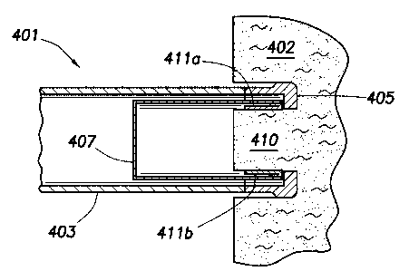
FIG. 4A is a cross section of a coring bit 401 with a retention member 411 in
accordance with one embodiment of the invention. FIG. 4A shows only the coring
bit 401,
but those having skill in the art will understand that the coring bit 401
forms part of a coring
tool (not shown) that is used to take core samples from a formation. By way of
example, the
coring bit may form part of a coring tool, such as the coring tool 101 in FIG.
1.
The coring bit 401 in FIG. 4A includes a hollow shaft 403 with a formation
cutter 405
disposed at a distal end of the shaft 403. The formation cutter 405, or
formation cutter, is
formed of a material for drilling into the formation 402. The formation cutter
405 may be
formed of a strong material that is coated with a super hard material, such as
polycrystalline
CA 02490492 2004-12-17
diamond or tungsten carbide. In other embodiments, the formation cutter 405
may include
other devices for cutting through soft formation, such as brushes. The term
"distal end" is
used to describe the end of the coring bit 401 that first contacts the
formation. The distal end
is the end of the shaft 403 that is the farthest from the center of the coring
tool (not shown)
while a sample is being taken. It is the first part of the coring bit 401 to
penetrate a
formation.
As shown in FIG. 4A, a coring bit 401 may include an internal sleeve 407 that
is
disposed inside the hollow shaft 403. The internal sleeve 407 is for receiving
a core sample
(not shown in FIG. 4A) as it enters the coring bit 401. In some embodiments,
the internal
sleeve 407 is a "non-rotating" internal sleeve. A non-rotating internal sleeve
is an internal
sleeve that is free to rotate independent of the hollow shaft 403. Thus, as
the coring tool
penetrates a formation 402, friction between the internal sleeve and the core
sample (e.g., 410
in FIGS. 4B and 4C) prevents the internal sleeve from rotating with respect to
the formation
402. In some other embodiments, a mechanical stop, such as a key (not shown)
may prevent
the rotation of the internal sleeve. This reduces the erosion of the core
sample by eliminating
friction between the core sample and the internal sleeve during the sampling
process.
Examples of coring sleeves are disclosed in copending US Patent Application
Serial No.
10/248,475, assigned to the assignee of the present invention.
A retention member 411 is disposed at the distal end of the internal sleeve
407. The
retention member 411, as will be seen, enables a core sample to enter the
coring bit 401 and
the internal sleeve 407, and it also retains the core sample 410 in the
internal sleeve 407 once
the core sample 410 has been received in the coring bit 401.
FIG. 4B shows a cross section of a coring bit 401 in the process of receiving
a core
sample 410. As the formation cutter 405 penetrates the formation 402, a core
sample 410
enters the coring bit 401. As the core sample 410 enters the internal sleeve
407, it pushes the
petals 41 la, 411b of the retention member 411 out of the way so that the core
sample 410
may enter the coring bit 401. As the petals 411a, 411b move, they apply a
radially inward
force to the core sample 410 that serves to guide the core sample 410 and hold
it in place.
FIG. 4C shows a cross section of a coring bit 401 that has received a core
sample 410
in the internal sleeve 407 disposed inside the hollow shaft 403 of the coring
bit 401. The core
sample 410 is retained in the coring bit 401 by the petals 411a, 41 lb of the
retention member
(411 in FIG. 4A) in at least two ways. First, the petals 411a, 411b press
inward on the core
6
CA 02490492 2004-12-17
sample 410 to stabilize it and hold it in place. Second, when the coring bit
401 retracts from
the formation 402, the petals 411a, 411b will tend to close and grip the core
sample 410. In
hard rock, the additional friction between the core sample 410 and the petals
411a, 411b will
act as a wedge gripper that retains the core sample 410 in the coring bit 401.
In soft rock, the petals 411a, 411b may completely close and trap the core
sample 410
in the coring bit 401. This may be advantageous because of the tendency of
unconsolidated
or soft formations to fall out of the coring bit. Instead of losing 3/o inch
(~1.9 cm) to 1 inch
(~2.5 cm) of the core sample of an unconsolidated formation, the petals 411a,
41 lb may close
to retain the core sample 410 in the coring bit 401. The only core sample 410
that is lost is
that part of the core sample that extends past the petals S l l a, S l lb. In
some embodiments,
the petals are about '/4 inch (~0.6 cm) in length, and about '/4 inch of the
core sample is lost in
the closing of the petals. This assists in capturing and retaining core
samples of a soft
formation that can simply fall out of the coring bit when the sample is taken
using a
conventional coring bit.
The retention member 411 shown in FIGS. 4A, 4B, and 4C is preferably made of
rubber, although it can be made of any material that is flexible and still has
a memory. A
material with a memory will "remember" its original position such that it will
tend to move
back to its original position whenever it is displaced. In some embodiments,
material remains
in the elastic deformation regime even when completely displaced by the core
sample. Thus,
when the petals of a retention member are pushed radially outward by a core
sample, the
petals are flexible enough to give way so that the core sample can easily
enter the coring bit,
but they also tend to push radially inward toward their original position.
This tendency to
move back to the original position is what creates the radial pressure against
the core sample
that will guide it into the coring bit and retain it there while the coring
bit is being withdrawn
from the formation.
In some embodiments, a retention member may not be attached at a distal end of
an
internal sleeve. For example, FIG. SA shows a coring bit 501 with an internal
sleeve 507
disposed inside a hollow coring shaft 503. A formation cutter 505 is disposed
at the distal
end of the hollow coring shaft 503. The retention member 511 is located near
the mid-point
along the axial length of the internal sleeve 507. In this position, a
retention member 511
provides guidance so that a core sample (not shown) will be maintained near
the axial center
of the internal sleeve 507, while still offering the ability to retain the
core sample in the
7
CA 02490492 2004-12-17
coring bit 501 when the bit is withdrawn from the formation (not shown). For
example, in a
hard formation, the retention member 511 may act as a wedge gripper that
retains the core
sample (not shown) in the coring bit 501.
FIG. SB shows another embodiment of a coring bit with a retention member 521
in
accordance with the invention. The coring bit 521 includes a hollow coring
shaft 523 with a
formation cutter 525 at its distal end. A retention member 531 is held in the
center opening
of the formation cutter by a ring 533 in the formation cutter. In this
position, the retention
member 531 may enable a core sample (not shown) to enter the coring bit 521,
and it may
also retain the core sample in the coring bit 521 once the sample is received.
It is noted that a coring bit in accordance with the invention may have
various
combinations of the described features. For example, may include a retention
member
located as shown in FIG. SA, but without an internal sleeve. In another
example, a coring bit
may include a ring (e.g., ring 533 in FIG. SB) that is not disposed proximate
the distal end of
the coring bit. Those having ordinary skill in the art will be able to devise
other embodiments
of an coring bit that do not depart from the scope of the invention.
FIG. 6A shows an end view of a retention member 601 in accordance with one
embodiment of the invention. The retention member 601 has three petals 602a,
602b, 602c
that are cut from the center of the retention member 601 out to an outer petal
circumference
605. In some embodiments, the petal circumference 605 is substantially the
same size as the
inner diameter of the formation cutter (e.g., 505 in FIGS. SA, SB. and SC).
This enables the
core sample to fit snugly through the retention member. In other embodiments,
the petal
circumference 605 may be larger than the inner diameter of the formation
cutter (e.g., 505 in
FIGS. SA, SB. and SC).
The petals 602a, 602b, 602c shown in FIG. 6A are located adjacent to one
another.
That is, the edges of one petal, 602a for example, are adjacent to edges on
the other petals,
602b, 602c, for example.
In some embodiments, a retention member 601 includes cuts or perforations 607.
The
cuts 607 provide additional flexibility for the petals 602a, 602b, 602c when
the retention
member 601 is constructed of a stiff material or when there are only a small
number of petals
making each petal stiff.
8
CA 02490492 2004-12-17
FIG. 6B shows an embodiment of a retention member 621 with petals 622a, 622b,
622c that are not adjacent to each other. In this embodiment, the petals 622a,
622b, 622c are
separated from each other going back to the petal circumference 625.
FIG. 6C shows another embodiment of a retention member 631 in accordance with
the invention. The petals 637, 638, 639 overlap with each other. For example,
petal 637 has
edge 637a that overlaps edge 639b of petal 639. The other edge 637b of petal
637 is
overlapped by edge 638a of petal 638. Similarly, petal 639 has edge 639a that
overlaps edge
638b of petal 638.
FIG. 6D shows another embodiment of a retention member 641 in accordance with
the invention. The retention member includes an aperture 646 at its center.
The aperture 646
is created because the retention member 641 extended inwardly only to an
aperture
circumference 647. A core sample (not shown) may push its way through the
aperture 646
by displacing the retention member 641. The elasticity of the retention member
641 will
cause the retention member 641 to exert an inward force on the core sample
when it is
received.
FIG. 6D also shows some other optional features of a retention member. For
example, a retention member 641 with an aperture 646 may not have any petals.
A core
sample may simply displace a solid retention member. In other embodiments,
such as the
one shown in FIG. 6D, the retention member 641 may include one or more petals
642a, 642b,
642c. The petals 642a, 642b, 642c may be individual petals, or the petals
642a, 642b, 642c
may be perforated with perforations 643 extending between the aperture
circumference 647
to the petal circumference 645. When a core sample (not shown) is taken, the
core sample
will break the perforations 643, and the core sample may be received in the
coring bit (not
shown).
In fact, it is noted that the many of the above disclosed embodiments of a
retention
member may use radial perforations to segment the retention member into
petals. This would
enable the retention member to serve as a cover that will prevent contaminants
from entering
the coring bit before a sample is taken and the perforations are broken.
It is noted that radial perforations are distinguished from circumferential
perforations
that may be used to increase the flexibility of the retention member.
9
CA 02490492 2004-12-17
FIGS. 7A-7E show various embodiments of a retention member for use with a
coring
bit in accordance with the invention. FIG. 7A shows a retention member 711
with petals
711 a, 711 b that are tapered inwardly. The petals 711 a, 711 b have a petal
circumference that
is substantially the same as the inner diameter of the formation cutter 705. A
core sample
will snugly pass through the petals 711a, 711b of the retention member 711.
FIG. 7B shows another embodiment of a retention member 721 where the petals
721a,
721b are tapered outwardly. In this embodiment, when the petals 721a, 721b are
displaced
by a core sample (not shown), the pressure applied by the petals 721a, 721b
will be slightly
greater because they are displaced farther from their original position.
FIG. 7C shows another embodiment of a retention member 731 in accordance with
the invention. The petals 731a, 731b of the retention member 731 are rounded
and extruding
into the internal sleeve 707. When a core sample (not shown)is received in the
internal
sleeve 707, the petals 731a, 731b will be displaced inwardly.
FIG. 7D shows another embodiment of a retention member 741 in accordance with
the invention. The petals 741a, 741b of the retention member 741 are rounded
and extruding
outwardly from the internal sleeve 707. When a core sample (not shown) is
received in the
internal sleeve 707, the petals 741a, 741b will be displaced inwardly.
FIG. 7E shows an embodiment of a retention member 751 that is similar to that
shown
in FIG. 7B. In FIG. 7E, the internal sleeve 757 has a notch 753 that provides
space for the
petals 751a, 751b in their displaced position. The inner diameter D2 of the
internal sleeve
757 in the notch 753 is larger than the nominal diameter D1 of the internal
sleeve 757. In the
embodiment shown, the nominal diameter D1 of the internal sleeve 757 is
substantially the
same as the inner diameter of the formation cutter 705. As a core sample (not
shown) passes
into the internal sleeve 757, the petals 751a, 751b of the retention member
751 will be
displaced into the notch 753. The petals 751a, 751b, when displaced into the
notch 753, have
substantially the same inner diameter as the nominal diameter D1 of the
internal sleeve 757.
This enables the core sample 701 to fit snuggly at all points along the axis
of the internal
sleeve 757, while still gaining the advantages of a retention member in
accordance with
embodiments of the invention.
The embodiment of an internal sleeve 757 that is shown in FIG. 7E may be used
with
various embodiments of a retention member. For example, an internal sleeve 757
with a
CA 02490492 2004-12-17
notch 753 may be used with any of the embodiments of a retention member shown
in FIGS.
7A-7E.
A retention member in accordance with any of the embodiments of the invention
may
be designed specifically for a single use, or it may be designed to capture
and retain multiple
cores. For example, some coring bits are designed so that the core samples are
stored in the
internal sleeve. That is, the internal sleeve is moved from inside the coring
bit into a storage
area. In other embodiments, only the core sample is moved into a storage
device, and the
internal sleeve is used to capture another sample.
As will be understood by those having ordinary skill in the art, FIGS. 7A-7E
show a
cross section of particular embodiments of a coring bit and a retention member
in accordance
with the invention. As such, the figures show only two petals in each
embodiment. This is
simply a function of a cross section, and it is not intended to limit the
invention. A retention
member in accordance with the invention may have any number of petals.
Optionally, the
retention member may be uniform, solid, tapered, or have one or more apertures
therethrough. Other configurations may be envisioned. The retention member may
be
adapted to tear and/or stretch as the core sample advances into the sleeve.
Portions of the
retention member that are stretched or torn may apply force to the core sample
to grip the
core sample. The retention member is preferably elastic so that it may retract
to substantially
its original configuration and close behind the core sample thereby
restricting portions of the
core sample from exiting the coring sleeve.
FIG. 8A shows a cross section of a coring bit 800 with an internal sleeve 807
having a
piston 802 in accordance with the invention. The piston 802 is axially
moveable with respect
to the internal sleeve 807. The piston 802 is initially positioned proximate
the distal end of
the internal sleeve 807. When a core sample is being collected from the
formation 810, the
core sample will displace the piston 802 with respect to the internal sleeve
807. The piston
802 may also include seals 812 or bearings to enable easier movement of the
piston 802
within the internal sleeve 807.
In the embodiment shown, the internal sleeve 807 has a diameter that is
substantially
the same as the inner diameter of the formation cutter 805. In order to fit
with the internal
sleeve 807, the piston 802 has a diameter that is substantially the same as
the inner diameter
of the internal sleeve 807 so that the piston seals 812 are able to form a
seal between the
internal sleeve 807 and the piston 802.
11
CA 02490492 2004-12-17
FIG. 8B shows a cross section of the coring bit 800 with a core sample 801
received
inside the coring bit 800. The core sample 801 has displaced the piston 802 to
a position
proximate the proximal end of the internal sleeve 807. The piston 802 moves as
the core
sample 801 is received in the coring bit 800. Thus, the piston 802 provides
support for the
core sample 801. This may be advantageous in unconsolidated formations, where
the
formation core sample would fall apart as it came into the coring bit. The
piston 802 may
prevent the formation from falling apart.
Additionally, when the coring bit 800 is withdrawn from the formation 810, the
piston
802 helps to hold the core sample in the internal sleeve 807. In some
embodiments, the
chamber 815 behind the piston 802 includes a check valve or other means (not
shown) to
allow air or fluid to be pushed out of the chamber 815, but that will not
allow the return flow.
Thus, a vacuum behind the piston 802 will prevent the piston 802 from moving
on the
outward direction.
In some embodiments, the chamber 815 behind the piston is completely vented.
Nonetheless, the core sample 801 may not be able to move out of the internal
sleeve 807
without also moving the piston 802. This may be caused by a vacuum created
between the
piston 802 and the core sample 801. The friction between the piston 802 and
the internal
sleeve 807 will create additional resistance to the movement of the core
sample 801, which
will help retain the core sample 801 in the coring bit 800.
Further, in addition to a simple piston 802, the internal sleeve 807 may also
include a
ratchet device or a locking device. Such a device would prevent the piston
from moving in
the outward direction.
FIG. 9 shows a cross section of a coring bit 900 that includes a cushion for
receiving
and retaining the core sample 901 in the bit 900. A hollow outer shaft 903
penetrates a
formation 910 using a formation cutter 905 disposed at the distal end of the
shaft 903. A core
sample 901 is received in an internal sleeve 917 that is disposed inside the
hollow shaft 903.
The cavity (shown at 918) in the internal sleeve 917 behind the core sample
901 is
filled with a fluid, such as water. The proximal end of the internal sleeve
917 includes a
valve 921 for selectively permitting fluid to pass between the sleeve 917 and
the rest of the
tool. The valve 921 may be, for example, a check valve that enables the fluid
to exit the
cavity 918 as a core sample 901 moves into the internal sleeve 917. When the
coring bit 900
12
CA 02490492 2004-12-17
is withdrawn from the formation, the valve 921 may be used to prevent the
reverse flow of
fluid into the cavity 918, and a vacuum is created behind the core sample 901
that retains the
core sample 901 in the coring bit 900.
In at least one embodiment, the check valve 921 in FIG. 9 may be combined with
the
coring bit 800 in FIGS. 8A and 8B. In such an embodiment, the piston (802 in
FIGS. 8A and
8B) would force the fluid through the check valve (921 in FIG. 9). The check
valve (921 in
FIG. 9) would prevent the return flow of fluid and the vacuum behind the
piston (802 in
FIGS. 8A and 8B) and, thereby, retain the piston core sample in place.
FIG. 10 shows a cross section of a coring bit 1001 in accordance with another
embodiment of the invention. A hollow shaft 1003 has a formation cutter 1005
at a distal end
of the shaft 1003. A bladder 1007 is used as an internal sleeve in the coring
bit 1001 in FIG.
10. The bladder 1007, when deflated, provides enough space to accept a core
sample. The
bladder 1007 may then be selectively inflated by filling it with fluid. The
fluid may be stored
hydraulic fluid, or it may be drilling mud that is pumped into the bladder.
The type of fluid
used is not intended to limit the invention.
When the bladder 1007 is filled, it will compress inwardly and exert a radial
pressure
on a core sample (not shown). The pressure will apply an overburden to the
core sample that
will both stabilize and retain the core sample.
Embodiments of the invention may present one or more of the following
advantages.
A coring bit with a retention member or other retention device in accordance
with the
invention will retain the core sample in the coring bit while the coring bit
is being withdrawn
from the formation. This will prevent the core sample from being damaged or
lost during this
process.
Advantageously, a coring bit may include a retention member that will close
completely when capturing a sample in soft or unconsolidated formation. When
the retention
member closes, the core sample will be completely enclosed in the coring bit
and protected
against further damage and loss.
Advantageously, a coring bit that includes a non-rotating internal sleeve will
not
degrade the core sample through friction between the core sample and the
internal sleeve and
the retention member. The internal sleeve and the retention member will not
rotate with
respect to the formation and the core sample as it is being captured.
13
CA 02490492 2004-12-17
Advantageously, embodiments of the invention that include a piston in the
internal
sleeve provide additional guidance for a core sample as it is being received.
The piston is
displaced by the core sample, and once the sample is fully received, the
piston creates a
vacuum or void behind the core sample that retains the core sample in the
internal sleeve as
the coring bit is withdrawn from the formation.
Advantageously, embodiments of the invention that include a cushion provide
steady
guidance for the core sample as it enters the coring bit. Once received in the
coring bit, the
core sample is retained by a vacuum or void behind the core sample.
While the invention has been described with respect to a limited number of
embodiments, those skilled in the art, having benefit of this disclosure, will
appreciate that
other embodiments can be devised which do not depart from the scope of the
invention as
disclosed herein. Accordingly, the scope of the invention should be limited
only by the
attached claims.
14