Note: Descriptions are shown in the official language in which they were submitted.
CA 02490637 2004-12-22
WO 2004/001310 PCT/FI2003/000479
1
METHOD AND BURNER FOR ROTARY KILNS
The present invention relates to a method of and a burner for generating a
flame by
means of the burner in a combustion zone of a rotary kiln.
Rotary kilns are typically used for treating various solid substances,
especially when
the treatment requires high temperature. Also typically, the treatment
processes are
endothermic, i.e. they require introduction of external heat into the kiln
from outside of
1o the kiln. Some examples of this kind of processes are e.g. reduction of
oxidized ores
and oxided concentrates and calcination of various compounds, such as
combustion
of clinker and lime. Treated material exiting the kiln is often hot and in
order to
improve heat economy, the heat therein is recovered e.g. by means of
preheating the
combustion air being introduced into the kiln.
Heat sources utilized in the kilns include liquid, gaseous and solid fuels,
such as oil,
natural gas and carbon dust. The burner is attached to the hot end of the
kiln.
Usually the burner has the construction of a multi-passage tube introduced
through
the end of the kiln via an opening arranged therein. The discharge end of the
burner
2o extends into the kiln to a location, which is optimal in view of both fuel
combustion and
heat transfer, which location depends on requirements set by the process
practiced in
the kiln. In some cases, the burner tube may extend only to the level of the
inner
surface of the burner end, but it may also extend several meters into the
kiln. The
burner tube is provided with passages for fuel (fuels) and combustion air,
possibly
also for additives necessary for the operation of the process.
Especially in treatment processes producing a hot product (clinker, lime, so-
called
lime sludge), the heat therein is recovered by transferring it into combustion
air
required in the firing of the fuel used in the process. In such a case, this
air (so-called
3o secondary air) is usually directed into the kiln by-passing the burner, and
only so-
called primary air is directed through the burner, which primary air is
necessary for
igniting, stabilizing (maintaining a constant ignition point) and forming of
the flame.
The proportion of primary air varies depending on individual burners and
applications,
but most typically it is 10-40 % of the total volume of combustion air. The
primary air
is directed to the burner in order to ensure controlled ignition of the fuel
and a
CA 02490637 2004-12-22
WO 2004/001310 PCT/FI2003/000479
2
constant ignition point (stabilizing of the flame) and to achieve a controlled
form of
the flame in the kiln. The primary air is led to the burner via a fan of its
own.
However, the present primary air arrangements do not always provide for the de-
sired results in view of both flame control and heat economy of the kiln.
Moreover,
the ever more exacting environmental requirements set increasingly tight
limits to
nitrogen oxides emissions. For example, reducing the amount of primary air
typi-
cally results in a decrease in nitrogen oxide emissions, but at the same time
compli-
cates controlling the form of the flame, as well as adjusting the center of
combus-
to tion. These, in turn, are factors, which have an effect on e.g. the heat
economy of
the process. The object of the present invention is to provide a method and a
burner for more efficient controlling of combustion in a rotary kiln, such as
a lime
kiln, at the same time resulting in decreased detrimental emissions, e.g.
nitrogen
oxide emissions, compared to prior art systems.
The characteristic features of the present invention are disclosed in the
appended
claims. The invention is essentially based on the use of flue gas from a gas
turbine
instead of air as the source of primary air. Thus, a primary air fan has been
re-
placed by a gas turbine.
In known burners, primary air is introduced at an overpressure of a few kPa,
which
primary air is un-preheated or slightly preheated, typically having a
temperature of
e.g. 150-200 °C. Air is known to contain oxygen in the amount of about
21 % of its
volume. In the new burner, gas exiting the turbine and entering the burner
tube
most often has an oxygen content of 15-16% and a temperature of 400-
800°C, de-
pending on the capacity of the turbine and pressure loss of the burner tube.
The object of the exhaust gas of the gas turbine is just the same as the
object of air
introduced by means of a primary air fan, but in the burner arrangement
according
3o to the invention the amount of air introduced to the ignition is clearly
smaller than in
known burners and with smaller flow volumes of oxygen and gas, typically only
4-
10% of the total amount of combustion air. The fuel flow required by a gas
turbine
is very small compared to the main fuel flow, usually only a few percents.
CA 02490637 2004-12-22
WO 2004/001310 PCT/FI2003/000479
3
A characteristic feature of the burner is that multiple various fuels may be
burned
therein simultaneously, even if they represent all three forms, e.g, solid,
liquid and
gaseous forms.
The invention may preferably be applied in lime sludge kilns, lime kilns and
cement
kilns.
Other air required in the kiln in addition to primary, such as secondary air,
bypasses
the burner. Typically the secondary air is heated by causing it to contact
with the
l0 material combusted in the kiln.
The present invention is explained in more detail with reference to the
appended
Figures, in which
Fig. 1 represents a preferred burner arrangement according to the invention,
and
Fig. 2a and 2b represent a second preferred burner arrangement according to
the
invention.
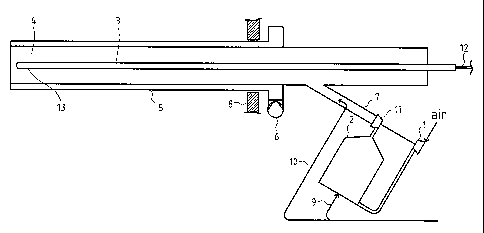
The construction and implementation principle of the burner is illustrated in
Figure 1.
The burner is formed of a tube 4, which extends into the kiln via an opening
in the
2o end wall 8 of the kiln. Exhaust gas from a gas turbine, i.e. primary air is
led to the
discharge end of the burner via the burner tube. Fuel, e.g. heavy oil, may be
intro-
duced conventionally by leading it from line 12 by means of a tube 3 (burner
lance)
of its own into a nozzle located in the discharge end 13 of the burner tube 4.
A con-
ventional embodiment comprises arranging it concentrically inside the burner
tube
so that it is surrounded by primary air, but other construction solutions are
also pos-
sible. Depending on the quality of the fuel, it may also be fed into the
forward end
of the burner tube, in which case it will be mixed into primary air flowing in
the tube
and inflame in the formed mixture.
3o According to the invention, a gas turbine is connected to the burner, said
gas tur-
bine comprising a compressor 1, wherein air is led and a combustion chamber 2
and turbine 11 connected thereto. Fuel in line 9, such as natural gas or oil,
and air
from the compressor, are led into the combustion chamber 2, the flue gases
(i.e.
primary air) from which combustion chamber are led via the turbine 11 rotating
the
CA 02490637 2004-12-22
WO 2004/001310 PCT/FI2003/000479
4
compressor. The power requirement of the compressor 1 from the turbine 11 for
generating the pressure needed in the combustion chamber is so small that the
temperature decrease of the gas in the turbine is usually only 50-100
°C.
A characteristic feature of the burner arrangement is that gas (primary air)
gener-
ated in the combustion chamber 2 and exiting the gas turbine is fed via a
short
connecting tube 7 into the actual burner tube 4. The connecting tube 7 is most
suitably constructed so that it is connected to the burner tube 4 outside the
burner
end 8 of the kiln.
The gas turbine unit with its combustion chamber is relatively light weighted.
It may
be positioned separate from the burner tube, if desired, but preferably the
burner
tube, gas turbine unit and the connecting tube between them are integrated so
that
the gas turbine unit is supported to the burner tube via the connecting tube
and, if
needed, additional supports. An advantage of this kind of unit formed of the
gas
turbine and burner tube connected together is that its position in relation to
the kiln
may be changed. This also has an effect on the operation of the kiln: The
burner
tube is not always located in the direction of the longitudinal axis of the
kiln, but it is
typically inclined in the direction of the material bed to be treated, in
order to inten-
2o sify heat transfer from the flame to the bed. A fixed connection is
preferable also
constructionally, as the connection between the gas turbine and the burner
tube is
effected with a stationary connecting tube instead of using a flexible hose,
which
has to stand temperatures up to 800 degrees of Celsius, when necessary. A pos
sibly needed cooler fan for the burner may be connected to the burner tube in
a cor
responding way.
According to Fig. 1, the gas from the turbine is fed into the burner tube 4
via an in-
clined connecting tube 7. In principle, the gas may be fed either tangentially
from
the side of the burner or axially via the end of the burner. The gas pressure
loss in
3o the burner tube (back pressure of the gas turbine) depends on the feed
direction of
the gas, so that the least loss is obtained via axial feed and greatest via
tangential
feed, thus the optimal construction has to be decided for each case
individually.
Fig. 2a and 2b represent a burner arrangement, in which the gas from the gas
tur-
bine is led into the burner tangentially. In accordance with fig. 2a the
burner com-
CA 02490637 2004-12-22
WO 2004/001310 PCT/FI2003/000479
prises a burner lance 23, a casing tube 30 for the burner lance, if needed, a
burner
tube 24 and a cooling air housing 25. In this embodiment the burner tube 24
com-
prises a cyclone part 32, which is connected to the straight part 24 of the
burner
tube via a cone 26. Fuel is fed into the burner lance 23 from line 33. The gas
from
5 the gas turbine is introduced into the cyclone part 32 via a connecting tube
27,
which connects the burner tube and the gas turbine and is attached
tangentially to
the cyclone part 32. The end wall of the kiln is marked with reference numeral
28.
Fig. 2b shows as a cross sectional view via line A-A of Fig. 2a the connection
of the
1o burner tube to the gas turbine. The gas turbine comprises a compressor 21,
a com-
bustion chamber 22 and a turbine 31. From the gas turbine the gas is led into
the
cyclone part 32 of the burner tube via connection tube 27, which is
tangentially con-
nected to the cyclone 32. Fuel is introduced into the combustion chamber via
line
29.
The amount of ignition energy at the discharge end of the burner may be
increased,
if needed, by means of so-called intermediate combustion. Normally the burner
tube is dimensioned so that the fuel fed therein cannot burn in the tube, but
in-
flames only when the mixture is discharged from the burner into the kiln.
Interme-
2o diate combustion is enabled by providing the burner tube with a zone, in
which the
flow speed of primary air is reduced to be lower than the propagation speed of
the
flame front by locally increasing the cross-sectional flow area of primary
air. A pre-
ferred method of implementing intermediate combustion is to arrange the zone
in
the front end of the burner tube and led the exhaust gas from the gas turbine
into
the burner tube tangentially so that a cyclone-shaped intermediate burner is
formed
in the front end of the burner tube, as shown in Fig. 2a and 2b. This way, the
tem-
perature of the gas may be increased to be even more than 1000 degrees centi-
grade, if necessary. The fuel necessary for the temperature increase is
usually
fed into the connecting tube 7 between the gas turbine and the burner tube via
line
10 in Fig. 1 and into the connecting tube 27 in Fig. 2b. The space required
for in-
termediate combustion does not necessarily need to be located in the front end
of
the burner tube, but may be arranged in another location therein.
As the exhaust gas from the gas turbine has a temperature of several hundred
de-
grees (400-800°C), the portion of the burner located inside the kiln
tends to become
CA 02490637 2004-12-22
WO 2004/001310 PCT/FI2003/000479
6
hotter than when using cooler primary air. For this reason, in the arrangement
ac-
cording to the invention, the burner tube is preferably cooled. According to
the prin-
cipal construction illustrated in the figures, the burner is provided with a
concentrical
outer housing 5 and cooling air is introduced between the housing and the
actual
burner tube 4 by means of a fan 6, which air exits via an annular slot between
the
tubes into the kiln (flame). A typical amount of cooling air is only 1-3% of
the total
combustion air flow. In individual objects, thermal insulation around the
burner tube
may be provided for increased protection.
1o By means of a burner according to the invention, the nitrogen oxide level
can be
reduced compared to using burners operating with air. The most important way
to
minimize the emission level is considered to be decreasing the amount of
primary
air (primary oxygen) and fastening the temperature increase in the flame after
igni-
tion, due to increased amount of ignition energy.. Fast burning results in
oxygen
deficit in the flame and the combustion zone of the kiln, due to which thermal
NO is
mostly generated via OH radicals, which react to NO remarkably slower than
free
oxygen. The oxidation of nitrogen contained in the fuel to NO reduces as the
oxy-
gen content decreases, while the reduction of NO to molecular nitrogen
increases.
2o Compared to present rotary kiln burners, the new solution also provides for
better
controllability of the flame in view of both the form of the flame and the
rate of com-
bustion. The latter is regulated by the capacity of the gas turbine, which
affects the
volume of exhaust gas flow from the turbine and the temperature of the flow.
The
combustion velocity also has an effect on the height of the flame and the
burning
temperature, and further the heat transfer from the flame to the material
being proc-
essed in the kiln.
The burner also provides for a larger power adjustment zone than present
rotary
kiln burners. Stable combustion is possible even at very low power, because an
3o amount of energy corresponding to the full capacity of the gas turbine may
in the
best case be introduced into the burner as ignition energy, simultaneously
maintaining the main feed of fuel at a very low level without causing the
burner to go
out.