Language selection

Search

Patent 2490656 Summary

Third-party information liability

Some of the information on this Web page has been provided by external sources. The Government of Canada is not responsible for the accuracy, reliability or currency of the information supplied by external sources. Users wishing to rely upon this information should consult directly with the source of the information. Content provided by external sources is not subject to official languages, privacy and accessibility requirements.

Claims and Abstract availability

Any discrepancies in the text and image of the Claims and Abstract are due to differing posting times. Text of the Claims and Abstract are posted:

  • At the time the application is open to public inspection;
  • At the time of issue of the patent (grant).
(12) Patent Application: (11) CA 2490656
(54) English Title: CABLE SHEAVE FOR A CABLEWAY SYSTEM
(54) French Title: POULIE A CABLE POUR SYSTEME DE CABLAGE
Status: Deemed Abandoned and Beyond the Period of Reinstatement - Pending Response to Notice of Disregarded Communication
Bibliographic Data
(51) International Patent Classification (IPC):
  • F16H 55/50 (2006.01)
(72) Inventors :
  • HAEFELE, NORBERT (Austria)
(73) Owners :
  • INNOVA PATENT GMBH
(71) Applicants :
  • INNOVA PATENT GMBH (Austria)
(74) Agent: SMART & BIGGAR LP
(74) Associate agent:
(45) Issued:
(22) Filed Date: 2004-12-22
(41) Open to Public Inspection: 2005-12-24
Examination requested: 2006-09-29
Availability of licence: N/A
Dedicated to the Public: N/A
(25) Language of filing: English

Patent Cooperation Treaty (PCT): No

(30) Application Priority Data:
Application No. Country/Territory Date
A 1074/2004 (Austria) 2004-06-24

Abstracts

English Abstract


A cable sheave for cableway systems has a hub and a sheave
surface extending outwardly from the hub. The sheave surface
may be formed of spokes and a cable groove is formed on its
periphery. Fastening devices are provided in the sheave
surface for rigidly connecting at least two sheave parts to
one another to form the complete cable sheave. The parting
line(s) is located outside the hub. Here, a first cable sheave
part containing the hub and forming the central region of the
cable sheave is provided, and at least two further, second
cable sheave parts are provided, which parts are of identical
size, radially surround the first cable sheave part, are
connected rigidly to the first cable sheave part and to the at
least one second cable sheave part which is present and by
means of which the cable groove is formed.


Claims

Note: Claims are shown in the official language in which they were submitted.

I Claim:
1. A cable sheave for cableway systems, comprising:
a hub;
a first cable sheave part containing said hub and at least two
second cable sheave parts connected to said first cable sheave
part, said first and second cable sheave parts defining a
sheave surface extending from said hub and having a periphery
with a cable groove formed therein;
fastening devices in said sheave surface for rigidly
connecting at least two of said cable sheave parts to one
another along a parting line located outside said hub;
said first cable sheave part containing said hub and forming a
central region of the cable sheaves
said at least two second cable sheave parts having a mutually
identical size, radially enclosing said first cable sheave
part, being rigidly connected to said cable first sheave part
and to a respectively other said second cable sheave part, and
defining said cable groove.
2. The cable sheave according to claim 1, wherein said sheave
surface is configured with spokes between said hub and said
cable groove.
3. The cable sheave according to claim 1, wherein a radially
outer edge of said first cable sheave part is formed with at
least two flanges, disposed in circular symmetry with respect
to said hub, and said second sheave parts are formed with
flanges assigned to said flanges of said first cable sheave
part.
4. The cable sheave according to claim 3, wherein said first
cable sheave part is formed with at least two radially
protruding webs of equal length, and said webs are formed, at
free ends thereof, with flanges aligned at right angles to
said webs.
-7-

5. The cable sheave according to claim 3, wherein said second
cable sheave parts are connected to said first cable sheave
part along planes enclosing a right angle with respect to a
plane of symmetry of the respective said second cable sheave
part, wherein the plane of symmetry passes through said hub,
and wherein said second cable sheave parts that are disposed
next to one another are connected to one another along
rectilinear planes that pass through said hub.
6. The cable sheave according to claim 1, wherein said first
cable sheave part is formed with radially protruding webs, a
number of said webs being equal to a number of said second
cable sheave parts, said second cable sheave parts are formed
with webs extending in continuation of said radial webs of
said first cable sheave part and are radially aligned, and
peripheral webs extend in a form of a segment of a circle and
have free ends disposed next to one another are rigidly
connected to one another.
7. The cable sheave according to claim 1, wherein said at
least two second cable sheave parts are four second cable
sheave parts.
8. A kit for producing cable sheaves of mutually different
diameters, comprising: a first cable sheave part with a hub;
and at least two groups of second cable sheave parts formed
with a cable groove, said second cable sheave parts of
mutually different groups of second cable sheave parts having
mutually different radial lengths.
-8-

Description

Note: Descriptions are shown in the official language in which they were submitted.


CA 02490656 2004-12-22
CA 34379
CABLE SHEAVE FOR A CABLEWAY SYSTEM
Background of the Invention:
Field of the Invention:
The present invention relates to a cable sheave for cableway
systems. The cable sheave has a hub and a sheave surface which
surrounds the hub. The device is designed, if appropriate, in
the form of spokes, also has a cable groove formed on its
circumference. Fastening devices are provided in the sheave
surface, by way of which at least three sheave parts can be
connected rigidly to one another to form the complete cable
sheave, the parting lines being located outside the hub.
Commonly assigned European patent EP 1 099 880 B1 discloses a
cable sheave for cableway systems that comprises three cable
sheave parts connected rigidly to one another. The subdivision
of cable sheaves makes it possible to transport even cable
sheaves having very large diameters in containers of standard
sizes. A crucial factor of this design was for the parting
lines to be located outside the hub.
Since two mutual parallel parting lines were provided in the
prior cable sheave, the three cable sheave parts were,
however, of lengths which were equal to the diameter of the
cable sheave or were only slightly smaller than the same.
Summary of the Invention:
It is accordingly an object of the invention to provide a
cable sheave, which overcomes the above-mentioned
disadvantages of the heretofore-known devices and methods of
this general type. That is, it is an object of the invention
to further develop the prior cable sheave, firstly, such that
the parting lines run in such a manner that the individual
sheave parts have substantially smaller lengths or widths than
the diameter of the complete cable sheave and, secondly, the
intention is to provide a kit for producing cable sheaves
which enables cable sheaves having different diameters to be
produced.
-1-

CA 02490656 2004-12-22
With the foregoing and other objects in view there is
provided, in accordance with the invention, a cable sheave for
a cableway system, comprising:
a central hub;
a first cable sheave part containing the hub and at least two
second cable sheave parts connected to the first cable sheave
part, the first and second- cable sheave parts defining a
sheave surface extending from the hub and having a periphery
with a cable groove formed therein;
fastening devices in the sheave surface for rigidly connecting
at least two of the cable sheave parts to one another along a
parting line located outside the hub;
the first cable sheave part containing the hub and forming a
central region of the cable sheaves
the at least two second cable sheave parts having a mutually
identical size, radially enclosing the first cable sheave
part, being rigidly connected to the cable first sheave part
and to a respectively other the second cable sheave part, and
defining the cable groove.
In one embodiment, the sheave surface is configured with
spokes between the hub and the cable groove.
In other words, the objects of the invention are achieved in
that a first cable sheave part containing the hub and forming
the central region of the cable sheave is provided, and in
that at least two further, second cable sheave parts are
provided, which parts are of identical size, radially surround
the first cable sheave part, are connected rigidly to the
first cable sheave part and to the at least one second cable
sheave part which is present and by means of which the cable
groove is formed.
The radially outer edge of the first cable sheave part is
preferably formed with at least two flanges which axe arranged
in a circular symmetrical manner with respect to the hub, and
the second sheave parts are formed with flanges assigned to
-2-

CA 02490656 2004-12-22
the flanges of the first cable sheave part. In this case, the
first cable sheave part can be formed with at least two
radially protruding webs which have equal length and which are
formed at their free ends with flanges aligned at right angles
to the webs.
The second cable sheave parts are preferably connected to the
first cable sheave part along planes which enclose a right
angle with respect to the plane of symmetry of the particular
second sheave part, which plane of symmetry passes through the
hub, and the second cable sheave parts which are situated next
to one another are connected to one another along rectilinear
planes Which pass through the hub. Furthermore, the first
cable sheave part can be formed with radially protruding webs,
the number of webs being equal to the number of second cable
sheave parts, and the second cable sheave parts are formed
with webs which extend as a continuation of the radial webs of
the first cable sheave part and are likewise radially aligned,
and furthermore with peripheral webs which extend in the form
of a segment of a circle and the free ends of which, which are
situated next to one another, are connected to one another.
According to one preferred embodiment, the cable sheave is
formed with four second cable sheave parts.
A kit according to the invention for producing cable sheaves
with different diameters contains a first cable sheave part
having the hub, and at least two groups of second cable sheave
parts having the cable groove. The second cable sheave parts
of the different groups have different radial lengths, so that
differently sized sheaves may be assembled from the kit.
Other features which are considered as characteristic for the
invention are set forth in the appended claims.
Although the invention is illustrated and described herein as
embodied in a cable sheave for a cableway system, it is
nevertheless not intended to be limited to the details shown,
since various modifications and structural changes may be made
therein without departing from the spirit of the invention and
within the scope and range of equivalents of the claims.
The construction and method of operation of the invention,
however, together with additional objects and advantages
-3-

CA 02490656 2004-12-22
thereof will be best understood from the following description
of specific embodiments when read in connection with the
accompanying drawings.
Brief Description of the Drawings:
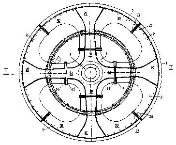
Fig. l is a plan view of a first embodiment of a cable sheave
according to the invention;
Fig. lA is a section taken along the line II-II in the cable
sheave according to Fig. 1;
Fig. 2 is a plan view of a second embodiment of a cable sheave
according to the invention;
Fig. 3 is a plan view of a detail of the cable sheaves
according to Figs. 1 and 2; and
Fig. 4 is a detail of the cable sheaves according to Figs 1
and 2, in a view along line IV-IV from Fig. 3.
Description of the Preferred Embodiments:
Referring now to the figures of the drawing in detail and
first, particularly, to Fig. 1 thereof, there is shown a cable
sheave with a central first cable sheave part 1 and four
second cable sheave parts 2 arranged around the first cable
sheave part 1. The parts 2 are in the form of a sector of a
circle and are connected rigidly to the first cable sheave
part 1 and to one another by way of mutually assigned flanges
11 and 21 or 22 and 23. The hub 3 is located in the center of
the first cable sheave part 1 and the cable groove 4 is
located on the outer edge of the second cable sheave parts 2.
The first cable sheave part 1 is formed with four radially
protruding webs 10, at the free ends of which the flanges 11
are located. The second cable sheave parts 2 are formed with
radial webs 20 which are a continuation of the webs 10 and on
the inner ends of which the flanges 21 are located and which
are adjoined by webs 30 which are in the form of a section of
a circle and on the free ends of which are located the flanges
22 and 23 by means of which the second cable sheave parts 2
are connected rigidly to one another with respect to the cable
sheave.
-4-

CA 02490656 2004-12-22
The advantage of this design is firstly that the cable sheave
parts produced in the factory are of sizes which can be
transported in containers, it being possible for them to be
assembled to form the cable sheave at the location at which
they are required for the cableway system. A further advantage
is secondly that for cable sheaves with different diameters
use can be made of a central first cable sheave part to which
second cable sheave parts located radially on the outside and
having different radial dimensions can be fitted. Also, it is
possible to manufacture the central part 1 with a high degree
of accuracy, which is necessary for integrating the central
bearing, and rigidity, while the outer parts 2 may be subject
to a lesser degree of accuracy and higher tolerances.
Reference is made for this purpose to the exemplary embodiment
which is illustrated in Fig. 2 and in which the central first
cable sheave part 1 is the same size as the first cable sheave
part 1 of the cable sheave according to Fig. 1, but to which
four second cable sheave parts 2' having smaller radial sizes
are joined, thus producing a cable sheave having a diameter
which is reduced in comparison to the cable sheave according
to Fig. 1. The second cable sheave parts 2' form the cable
groove 4. A cable sheave having a diameter which is enlarged
in comparison to Fig. 1 may also be produced in an analogous
manner.
As is apparent from Fig. 3 and 4, the flanges 11 and 21 are
connected to each other by means of a multiplicity of screw
bolts 25. In addition, conical guide bolts 26, to which guide
holes 27 are assigned in the flange 21, protrude from the
flange 11, as a result of which the installation of the outer
cable sheave parts 2 on the central cable sheave part 1 is
facilitated.
Cable sheaves of this type can be premanufactured with very
large diameters and transported to the location of the cable
way system where they are assembled to form the cable sheave.
Since the parting lines of the individual cable sheave parts 1
and 2 are located outside the hub 3, the functioning
capability of the hub 3 is not impaired. Since, for cable
sheaves having different diameters, use is made of a central
cable sheave part 1 which is the same size in all of the cable
-5-

CA 02490656 2004-12-22
sheaves, a modular system is provided, as a result of which
the production costs are reduced.
This application claims the priority, under 35 U.S.C. ~ 119,
of Austrian patent application No. A 1074/2004, filed June 24,
2004; the entire disclosure of the prior application is
herewith incorporated by reference.
-6-

Representative Drawing
A single figure which represents the drawing illustrating the invention.
Administrative Status

2024-08-01:As part of the Next Generation Patents (NGP) transition, the Canadian Patents Database (CPD) now contains a more detailed Event History, which replicates the Event Log of our new back-office solution.

Please note that "Inactive:" events refers to events no longer in use in our new back-office solution.

For a clearer understanding of the status of the application/patent presented on this page, the site Disclaimer , as well as the definitions for Patent , Event History , Maintenance Fee  and Payment History  should be consulted.

Event History

Description Date
Application Not Reinstated by Deadline 2011-12-22
Time Limit for Reversal Expired 2011-12-22
Deemed Abandoned - Failure to Respond to Maintenance Fee Notice 2010-12-22
Deemed Abandoned - Conditions for Grant Determined Not Compliant 2010-12-03
Notice of Allowance is Issued 2010-06-03
Letter Sent 2010-06-03
Notice of Allowance is Issued 2010-06-03
Inactive: Approved for allowance (AFA) 2010-05-31
Amendment Received - Voluntary Amendment 2010-01-29
Inactive: S.30(2) Rules - Examiner requisition 2009-11-13
Amendment Received - Voluntary Amendment 2009-09-09
Inactive: S.30(2) Rules - Examiner requisition 2009-04-20
Letter Sent 2006-10-18
Request for Examination Requirements Determined Compliant 2006-09-29
All Requirements for Examination Determined Compliant 2006-09-29
Request for Examination Received 2006-09-29
Application Published (Open to Public Inspection) 2005-12-24
Inactive: Cover page published 2005-12-23
Inactive: First IPC assigned 2005-04-01
Inactive: Filing certificate - No RFE (English) 2005-01-31
Letter Sent 2005-01-31
Application Received - Regular National 2005-01-31

Abandonment History

Abandonment Date Reason Reinstatement Date
2010-12-22
2010-12-03

Maintenance Fee

The last payment was received on 2009-11-18

Note : If the full payment has not been received on or before the date indicated, a further fee may be required which may be one of the following

  • the reinstatement fee;
  • the late payment fee; or
  • additional fee to reverse deemed expiry.

Patent fees are adjusted on the 1st of January every year. The amounts above are the current amounts if received by December 31 of the current year.
Please refer to the CIPO Patent Fees web page to see all current fee amounts.

Fee History

Fee Type Anniversary Year Due Date Paid Date
Registration of a document 2004-12-22
Application fee - standard 2004-12-22
Request for examination - standard 2006-09-29
MF (application, 2nd anniv.) - standard 02 2006-12-22 2006-10-20
MF (application, 3rd anniv.) - standard 03 2007-12-24 2007-11-16
MF (application, 4th anniv.) - standard 04 2008-12-22 2008-10-08
MF (application, 5th anniv.) - standard 05 2009-12-22 2009-11-18
Owners on Record

Note: Records showing the ownership history in alphabetical order.

Current Owners on Record
INNOVA PATENT GMBH
Past Owners on Record
NORBERT HAEFELE
Past Owners that do not appear in the "Owners on Record" listing will appear in other documentation within the application.
Documents

To view selected files, please enter reCAPTCHA code :


To view images, click a link in the Document Description column. To download the documents, select one or more checkboxes in the first column and then click the "Download Selected in PDF format (Zip Archive)" or the "Download Selected as Single PDF" button.

List of published and non-published patent-specific documents on the CPD .

If you have any difficulty accessing content, you can call the Client Service Centre at 1-866-997-1936 or send them an e-mail at CIPO Client Service Centre.


Document
Description 
Date
(yyyy-mm-dd) 
Number of pages   Size of Image (KB) 
Description 2004-12-21 6 242
Abstract 2004-12-21 1 21
Claims 2004-12-21 2 71
Drawings 2004-12-21 3 110
Representative drawing 2005-11-27 1 28
Claims 2009-09-08 3 95
Description 2010-01-28 6 238
Courtesy - Certificate of registration (related document(s)) 2005-01-30 1 105
Filing Certificate (English) 2005-01-30 1 158
Reminder of maintenance fee due 2006-08-22 1 110
Acknowledgement of Request for Examination 2006-10-17 1 176
Commissioner's Notice - Application Found Allowable 2010-06-02 1 167
Courtesy - Abandonment Letter (Maintenance Fee) 2011-02-15 1 173
Courtesy - Abandonment Letter (NOA) 2011-02-27 1 165
Fees 2006-10-19 1 29
Fees 2007-11-15 1 30
Fees 2008-10-07 1 35
Fees 2009-11-17 1 34