Language selection

Search

Patent 2490921 Summary

Third-party information liability

Some of the information on this Web page has been provided by external sources. The Government of Canada is not responsible for the accuracy, reliability or currency of the information supplied by external sources. Users wishing to rely upon this information should consult directly with the source of the information. Content provided by external sources is not subject to official languages, privacy and accessibility requirements.

Claims and Abstract availability

Any discrepancies in the text and image of the Claims and Abstract are due to differing posting times. Text of the Claims and Abstract are posted:

  • At the time the application is open to public inspection;
  • At the time of issue of the patent (grant).
(12) Patent Application: (11) CA 2490921
(54) English Title: STRIKER ASSEMBLY FOR A DOOR LOCK
(54) French Title: GACHE POUR SERRURE DE PORTE
Status: Deemed Abandoned and Beyond the Period of Reinstatement - Pending Response to Notice of Disregarded Communication
Bibliographic Data
(51) International Patent Classification (IPC):
  • E05B 15/02 (2006.01)
(72) Inventors :
  • ALCHIN, MICHAEL BRIAN (Australia)
(73) Owners :
  • AZUMA DESIGN PTY LIMITED
(71) Applicants :
  • AZUMA DESIGN PTY LIMITED (Australia)
(74) Agent: DEETH WILLIAMS WALL LLP
(74) Associate agent:
(45) Issued:
(22) Filed Date: 2004-12-23
(41) Open to Public Inspection: 2005-07-05
Availability of licence: N/A
Dedicated to the Public: N/A
(25) Language of filing: English

Patent Cooperation Treaty (PCT): No

(30) Application Priority Data:
Application No. Country/Territory Date
2004900034 (Australia) 2004-01-05

Abstracts

English Abstract


A striker assembly (10) to be attached to a door jamb to engage the tongue of
a
lock mounted on an associated doors the assembly (10) includes a base (11) to
be fixed to
the door jamb and a striker member (15). The striker member (15) is adjustable
relative
to the base (13).


Claims

Note: Claims are shown in the official language in which they were submitted.


-4-
CLAIMS:
1. A striker assembly to be engaged by a door lock, said assembly
including:
a base to be faced to a door jamb; and
a striker member adjustably fixed to the base and to be engaged by a tongue of
the lock.
2. The assembly of claim 1, wherein said striker member is adjustable
relative to the base in a generally horizontal direction.
3. The assembly of claim 2, wherein said base including a central portion
with opposite ends with a projection at each end, with said member being
located between
the projections.
4. The assembly of claim 3, wherein the projections extend horizontally
laterally from the central portion.
5. The assembly of claim 4, wherein said striker member is attached to
said base by means of threaded fasteners, with the base having elongated
apertures
through which the fasteners pass to provide for adjustment of the member
relative to the
base.
6. The assembly of claim 5, wherein said apertures are elongated
horizontally.
7. The assembly of claim 6, wherein said base and member are provided
with abutting surfaces that have ridges and troughs to inhibit relative
movement between
the base and member when the threaded fasteners are tensioned.
8. The assembly of claim 7, wherein said base includes apertures via
which the base is secured to the jamb with threaded fasteners.
9. The assembly of claim 8, wherein the base apertures are vertically
elongated to provide for adjustment of the base relative to the door jamb.
10. The assembly of claim 1, wherein said base including a central portion
with opposite ends with a projection at each cad, with said member being
located between
the projections.
11. The assembly of claim 1, wherein the projections extend horizontally
laterally from the central portion.
12. The assembly of claim 1, wherein said striker member is attached to
said base by means of threaded fasteners, with the base having elongated
apertures

-5-
through which the fasteners pass to provide for adjustment of the member
relative to the
base.
13. The assembly of claim 12, wherein said apertures are elongated
horizontally.
14. The assembly of claim 13, wherein said base and member are provided
with abutting surfaces that have ridges and troughs to inhibit relative
movement between
the base and member when the threaded fasteners are tensioned.
15. The assembly of claim 14, wherein said base includes apertures via
which the base is secured to the jamb with threaded fasteners.
16. The assembly of claim 15, wherein the base apertures are vertically
elongated to provide for adjustment of the base relative to the door jamb.
17. The assembly of claim 2, wherein the projections extend horizontally
laterally from the central portion.
18. The assembly of claim 17, wherein said striker member is attached to
said base by means of threaded fasteners, with the base having elongated
apertures
through which the fasteners pass to provide for adjustment of the member
relative to the
base.
19. The assembly of claim 18, wherein said apertures are elongated
horizontally.
20. The assembly of claim 19, wherein said base and member are provided
with abutting surfaces that have ridges and troughs to inhibit relative
movement between
the base and member when the threaded fasteners are tensioned.
21. The assembly of claim 20, wherein said base includes apertures via
which the base is secured to the jamb with threaded fasteners.
22. The assembly of claim 21, wherein the base apertures are vertically
elongated to provide for adjustment of the base relative to the door jamb.

Description

Note: Descriptions are shown in the official language in which they were submitted.


CA 02490921 2004-12-23
-1-
STRIKER ASSEMBLY FAR A Dt~OR LOCK
Technical Fieid
The present invention relates to strikers to be iced to a door jarr~b and
engaged
by a lock tongue, the lock being mounted on a door associated with the door
jamb.
s Background of the Invention
Both sliding and pivotally mounted doors are provided with a lock having a
tongue, with the tongue being adapted to engage a striker to retain the door
in the closed
position. 'fhe striker is attached to the door jamb.
Fox the lock tongue to correctly engage the striker, there needs to be an
accurate
io location of the striker and lock. Obtaining this correct location it is
often time consurrxing
and difficult. This is particularly evident in sliding doors where the doors
are adjustably
mounted on rollers.
Object of the Invention
It is the object of the presEnt invention to overcome or substantially
ameliorate
~s the above discussed problems.
Summary of the Invention
Them is disclosed herein a striker assembly to be engaged by a door lock, said
assembly including:
a base to be fixed to a door jamb; and
zo a striker merrxber adjustably fixed to the base and to be engaged by a
tongue of
the lock.
Preferably, said striker rn,ember is adjustable relative to the base in a
generally
horizontal direction.
Preferably, said base including a cEntral portion with opposite ends with a
2s projection at each end, with said member being located between the
projections.
Preferably, th.e projections extend horizontally laterally from the central
portion.
Preferably, said striker member is attached to said base by means of threaded
fasteners, with the base having elongated apertures through which the
Fasteners pass to
provide for adjustment of the member relative to the base.
ao Preferably, said apertures are Elongated horizontally.

CA 02490921 2004-12-23
-2-
Preferably, said base and member are provided with abutting surfaces that have
ridges and troughs to inhibit relative movement between the base and member
when the
threaded fasteners are tensiozted.
Preferably, said base includes apertures via which the base is secured to the
jamb
s with threaded fasteners.
Preferably, the base apertures are vertically elongated to provide for
adjustment
of the base relative to the door jamb.
Preferably, said assembly includes a cover secured to the base to conceal the
base apertures.
~o Brief Description of the Drawings
A preferred form of the present invention will nova be described by way of
example with reference to the accornpanying drawings wherein:
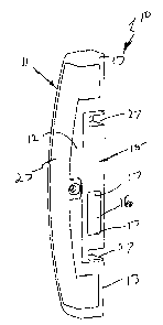
Figure 1 is a schematic front isometric view of a door striker assembly;
Figure 2 is a schematic front isometric view of the door striker assezxibly of
~s Figure 1 with a cover member removed;
Figure 3 is a schematic parts exploded perspective view of the striker
assembly
of Figure 1;
Figure 4 Xs a schematic front isometric view of a modification of the striker
assembly of Figure 1;
Zo Figure S is a schematic isometric view of the striker assembly of Figure 4
with a
cover member removed; and
Figure 6 is a schematic parts exploded perspective view of the striker
assembly
of figure 4.
i7etailed Description of the Preferred Embodiments
zs In the accompanying drawings thet~e is schematically depicted a striker
assembly
to be attached to a door jamb to engage the tongue of a lock mounted on the
door
operatively associated with the door jamb. In this particular embodiment, the
striker
assembly 10 is adapted to engage the "hook" tongue of a sliding door Lock.
However, it
should be appreciated that the present invention is also applicable to
strikers for pivotally
3o mounted doors.
The assembly x0 includes a base 11 to be fixed to the door jamb. The base 11
includes a central portion I2 at the upper and lower ends of which there is
pzovided
projections 13. The projections 13 project horizontally laterally beyond the
portion 12.

CA 02490921 2004-12-23
The projectiozzs 13 are provided with apertures 14 through which threaded
fasteners may
pass to secure the base 11 to the door jamb. In this respect, it should be
appreciated that
the apertures 14 are vertically elongated so that the base 11 may be adjusted
in height
relative to the door jamb and therefore the door and lock fixed thereto_
s Attached to the base 11 so as to be positioned between the projections 13 is
a
striker member 15. The striker member I 5 has an aperture 16 with upper and
lower edges
17 over which the "hook" tongue can engage. The member 15 has an abutment face
18 to
engage a corresponding abutment face 19 on the central portion 12. Preferably,
the faces
1$ and 19 are roughened or provided with ridges and troughs so that when the
striker
~u member 15 is attached to the base 11, the surfaces 18 and 19 inhibit
relative movement
between the member 15 and the base 11.
The central portion 12 is also provided with apertures 20 that are
horizontally
elongated and through which threaded fasteners 21 pass to engage threaded
passages 22
in the raembc;r 1 S. When the threaded fasteners 21 are tensioned, the member
15 is held
is in position between the projections 13. ~'he member 15 can be adjusted by
loosening the
fasteners 21 and moving the member 15 relative to the base 71. When a desired
position
is located, the threaded fasteners 21 are tensioned so that the faces 18 and
19 are firmly
held in frictional engagement.
A cover member 23 is secured to the base 11 by means of a threaded fastener 24
zo by passing through aperture 25 to engage threaded passage 26 in the base I
1 _ The cover
member 23 covers the threaded fasteners 21, and apertures 14 and 20.
In the embodiment of Figure 3, the merr~ber 15 is provided with slots 27 into
which projections of a sliding door lock would engage to x~xUibit lifting of
the sliding door
to remove the hook from engagement with the member I5.
as rn the embodiment of Figure 10, the striker member 15 has apertures 16 and
edges 17 over which a hook or hooks of the associated Iock would engage.

Representative Drawing
A single figure which represents the drawing illustrating the invention.
Administrative Status

2024-08-01:As part of the Next Generation Patents (NGP) transition, the Canadian Patents Database (CPD) now contains a more detailed Event History, which replicates the Event Log of our new back-office solution.

Please note that "Inactive:" events refers to events no longer in use in our new back-office solution.

For a clearer understanding of the status of the application/patent presented on this page, the site Disclaimer , as well as the definitions for Patent , Event History , Maintenance Fee  and Payment History  should be consulted.

Event History

Description Date
Application Not Reinstated by Deadline 2007-12-24
Time Limit for Reversal Expired 2007-12-24
Deemed Abandoned - Failure to Respond to Maintenance Fee Notice 2006-12-27
Application Published (Open to Public Inspection) 2005-07-05
Inactive: Cover page published 2005-07-04
Letter Sent 2005-03-15
Inactive: First IPC assigned 2005-03-08
Inactive: Single transfer 2005-02-18
Inactive: Courtesy letter - Evidence 2005-02-08
Inactive: Filing certificate - No RFE (English) 2005-02-03
Application Received - Regular National 2005-02-01

Abandonment History

Abandonment Date Reason Reinstatement Date
2006-12-27

Fee History

Fee Type Anniversary Year Due Date Paid Date
Application fee - standard 2004-12-23
Registration of a document 2005-02-18
Owners on Record

Note: Records showing the ownership history in alphabetical order.

Current Owners on Record
AZUMA DESIGN PTY LIMITED
Past Owners on Record
MICHAEL BRIAN ALCHIN
Past Owners that do not appear in the "Owners on Record" listing will appear in other documentation within the application.
Documents

To view selected files, please enter reCAPTCHA code :


To view images, click a link in the Document Description column. To download the documents, select one or more checkboxes in the first column and then click the "Download Selected in PDF format (Zip Archive)" or the "Download Selected as Single PDF" button.

List of published and non-published patent-specific documents on the CPD .

If you have any difficulty accessing content, you can call the Client Service Centre at 1-866-997-1936 or send them an e-mail at CIPO Client Service Centre.


Document
Description 
Date
(yyyy-mm-dd) 
Number of pages   Size of Image (KB) 
Claims 2004-12-22 2 80
Abstract 2004-12-22 1 9
Description 2004-12-22 3 131
Drawings 2004-12-22 4 72
Representative drawing 2005-06-06 1 4
Filing Certificate (English) 2005-02-02 1 158
Courtesy - Certificate of registration (related document(s)) 2005-03-14 1 105
Reminder of maintenance fee due 2006-08-23 1 110
Courtesy - Abandonment Letter (Maintenance Fee) 2007-02-20 1 175
Correspondence 2005-02-02 1 26