Language selection

Search

Patent 2491123 Summary

Third-party information liability

Some of the information on this Web page has been provided by external sources. The Government of Canada is not responsible for the accuracy, reliability or currency of the information supplied by external sources. Users wishing to rely upon this information should consult directly with the source of the information. Content provided by external sources is not subject to official languages, privacy and accessibility requirements.

Claims and Abstract availability

Any discrepancies in the text and image of the Claims and Abstract are due to differing posting times. Text of the Claims and Abstract are posted:

  • At the time the application is open to public inspection;
  • At the time of issue of the patent (grant).
(12) Patent: (11) CA 2491123
(54) English Title: BONE FIXATION ELEMENT
(54) French Title: ELEMENT DE FIXATION POUR OS
Status: Deemed expired
Bibliographic Data
(51) International Patent Classification (IPC):
  • A61B 17/86 (2006.01)
  • A61F 2/44 (2006.01)
  • A61F 2/00 (2006.01)
  • A61F 2/30 (2006.01)
(72) Inventors :
  • GOLDHAHN, JORG (Switzerland)
  • SEEBECK, JORN (Switzerland)
  • SCHNEIDER, ERICH (Switzerland)
(73) Owners :
  • SYNTHES USA, LLC (United States of America)
(71) Applicants :
  • SYNTHES (U.S.A.) (United States of America)
(74) Agent: OSLER, HOSKIN & HARCOURT LLP
(74) Associate agent:
(45) Issued: 2010-06-01
(86) PCT Filing Date: 2002-06-26
(87) Open to Public Inspection: 2004-01-08
Examination requested: 2007-06-11
Availability of licence: N/A
(25) Language of filing: English

Patent Cooperation Treaty (PCT): Yes
(86) PCT Filing Number: PCT/CH2002/000347
(87) International Publication Number: WO2004/002344
(85) National Entry: 2004-12-29

(30) Application Priority Data: None

Abstracts

English Abstract


A bone fixation element consisting of a hollow member having a wall, a
plurality of
perforations locating in the wall, a front end which is suited for insertion
into the bone, a
rear end, and a longitudinal axis. The stiffness of the hollow member may vary
along its
longitudinal axis from the rear end to the front end. Changes in the porosity
and/or the
thickness of the wall of the bone fixation element may result in changes in
stiffness of the
bone fixation element. An increase in porosity and/or decrease in thickness
may result in a
decrease in stiffness, and a decrease in porosity and/or increase in thickness
may result in an
increase in stiffness.


French Abstract

L'invention concerne un élément de fixation pour os (1) composé d'un cylindre creux (2), dont l'enveloppe (4) est pourvue de n perforations (3), ce cylindre étant doté d'une extrémité (5) ouverte antérieure, conçue pour être introduite dans l'os, d'une extrémité postérieure (6) et d'un axe longitudinal (7). La rigidité du cylindre creux (2) diminue le long de son axe longitudinal (7) de l'extrémité postérieure (6) vers l'extrémité antérieure (5). De par sa conception, cet élément de fixation pour os (1) satisfait aux exigences de rigidité adaptée et assure ainsi un ancrage à long terme dans l'os, notamment dans un os ostéoporeux, tout en respectant les conditions biologiques environnantes.

Claims

Note: Claims are shown in the official language in which they were submitted.


The embodiments of the invention in which an exclusive property or privilege
is
claimed are defined as follows:


1. A device for insertion in bone comprising a hollow member having a
longitudinal axis, a wall, a plurality of perforations in the wall, a front
end and a rear end,
wherein the perforations increase in one of size and number from the rear end
to the front end
and wherein the hollow member has a stiffness which decreases along the
longitudinal axis
from the rear end to the front end, and wherein a size of the perforations
changes along the
longitudinal axis.


2. The device of claim 1, wherein the stiffness of the hollow member decreases

continuously from the rear end to the front end.


3. The device of claim 1, wherein the stiffness of the rear third of the
hollow
member is at least about 20% greater than the stiffness of the front third of
the hollow
member.


4. The device of claim 1, wherein the rear end is provided with means for
accommodating a bone plate.


5. The device of claim 1, wherein the hollow member has a porosity which
increases from the rear end of the hollow member to the front end of the
hollow member.

6. The device of claim 5, wherein the porosity of the front third of the
hollow

member is at least about 20% greater than the porosity of the rear third of
the hollow
member.


7. The device of claim 1, wherein the hollow member has a wall thickness which

decreases from the rear end of the hollow member to the front end of the
hollow member.


8. The device of claim 7, wherein the wall thickness decreases continuously
from
the rear end of the hollow member to the front end of the hollow member.


-7-


9. The device of claim 7, wherein the wall thickness of the front third of the

hollow member is at least about 20% less than the wall thickness of the rear
third of the
hollow member.


10. The device of claim 1, wherein each of the plurality of perforations has a

diameter which is at least about 0.5 mm.


11. The device of claim 1, wherein the wall is a circumferential surface.


12. The device of claim 11 further comprising an external thread on at least a

portion of the circumferential surface.


13. The device of claim 1, wherein each of the plurality of perforations has a

shape selected from the group consisting of round, oval, square, triangular
and quadrilateral.

14. The device of claim 1, wherein the front end is open.


15. A device for insertion in bone comprising a hollow cylinder having a
longitudinal axis, a circumferential surface, a plurality of perforations in
the circumferential
surface, a front end and a rear end, wherein the perforations increase in one
of size and
number from the rear end to the front end and wherein the hollow cylinder has
a first stiffness
at the front end and a second stiffness at the rear end, the first stiffness
being less than the
second stiffness, and wherein a size of the perforations changes along the
longitudinal axis.


16. The device of claim 15, wherein the hollow cylinder has a height along the

longitudinal axis and each of the plurality of perforations has an area,
wherein the number of
perforations per tenth of the height of the hollow cylinder increases in a
first direction while
the area of each of the plurality of perforations remains constant, wherein
the first direction
extends from the rear end to the front end.


17. The device of claim 15, wherein the hollow cylinder has a height along the

longitudinal axis and each of the plurality of perforations has an area,
wherein the number of
perforations per tenth of the height of the hollow cylinder remains constant
while the area of

.
-8-


each of the plurality of perforations increases in the first direction,
wherein the first direction
extends from the rear end to the front end.


18. The device of claim 15, wherein the rear end is provided with means for
accommodating a bone plate.


19. The device of claim 15, wherein the hollow cylinder has a first porosity
at the
front end and a second porosity at the rear end, the first porosity being
greater than the second
porosity.


20. The device of claim 19, wherein the hollow cylinder has a first thickness
at the
front end and a second thickness at the rear end, the first thickness being
less than the second
thickness.


21. The device of claim 15, wherein each of the plurality of perforations has
a
shape selected from the group consisting of round, oval, square, triangular
and quadrilateral.

22. The device of claim 15, wherein the front end is open.


23. A device for insertion in bone comprising:
a hollow member having a longitudinal axis, a wall, a plurality of
perforations
in the wall, a front end and a rear end, wherein the hollow member has a
stiffness which
decreases along the longitudinal axis from the rear end to the front end,
wherein the
perforations at a first distance from one of the front end and the rear end
are the same size as
each other, and wherein the perforations at a second distance from one of the
front end and
the rear end are the same size as each other and different in size from the
perforations at the
first distance.


24. The device of claim 23, wherein the stiffness of the hollow member
decreases
continuously from the rear end to the front end.


-9-


25. The device of claim 23, wherein the stiffness of the rear third of the
hollow
member is at least about 20% greater than the stiffness of the front third of
the hollow
member.


26. The device of claim 23, wherein the rear end is provided with means for
accommodating a bone plate.


27. The device of claim 23, wherein the hollow member has a porosity which
increases from the rear end of the hollow member to the front end of the
hollow member.

28. The device of claim 27, wherein the porosity of the front third of the
hollow
member is at least about 20% greater than the porosity of the rear third of
the hollow
member.


29. The device of claim 23, wherein the hollow member has a wall thickness
which decreases from the rear end of the hollow member to the front end of the
hollow
member.


30. The device of claim 29, wherein the wall thickness decreases continuously
from the rear end of the hollow member to the front end of the hollow member.


31. The device of claim 29, wherein the wall thickness of the front third of
the
hollow member is at least about 20% less than the wall thickness of the rear
third of the
hollow member.


32. The device of claim 23, wherein each of the plurality of perforations has
a
diameter which is at least about 0.5 mm.


33. The device of claim 23, wherein the wall is a circumferential surface.


34. The device of claim 33 further comprising an external thread on at least a

portion of the circumferential surface.


-10-


35. The device of claim 23, wherein each of the plurality of perforations has
a
shape selected from the group consisting of round, oval, square, triangular
and quadrilateral.


36. The device of claim 23, wherein the front end is open.

37. A device for insertion in bone, comprising:
a hollow cylinder having a longitudinal axis, a circumferential surface, a
plurality of perforations in the circumferential surface, a front end and a
rear end, wherein the
hollow cylinder has a first stiffness at the front end and a second stiffness
at the rear end, the
first stiffness being less than second stiffness, wherein the perforations at
a first distance from
one of the front end and the rear end are the same size as each other, and
wherein the
perforations at a second distance from one of the front end and the rear end
are the same size
as each other and different in size from the perforations at the first
distance.


38. The device of claim 37, wherein the rear end is provided with means for
accommodating a bone plate.


39. The device of claim 37, wherein the hollow cylinder has a first porosity
at the
front end and a second porosity at the rear end, the first porosity being
greater than the second
porosity.


40. The device of claim 39, wherein the hollow cylinder has a first thickness
at the
front end and a second thickness at the rear end, the first thickness being
less than the second
thickness.


41. The device of claim 37, wherein each of the plurality of perforations has
a
shape selected from the group consisting of round, oval, square, triangular
and quadrilateral.

42. The device of claim 37, wherein the front end is open.


-11-

Description

Note: Descriptions are shown in the official language in which they were submitted.


CA 02491123 2009-03-23

BONE FIXATION ELEMENT
Cross Reference to Related Application

[0001] The present application is a continuation of published International
PCT
Application No. WO 2004/002344.

Field of the Invention

100021 The invention relates to a bone fixation element and, in particular, to
a device
for insertion into bone that promotes bone growth and has enhanced bone
anchoring
capability.

Background of the Invention

100031 Existing implants have inadequately addressed the reactions of the
surrounding tissue, especially of the bone, to a foreign body, namely the
implant. In
particular, the effect of using relatively stiff implants, such as those made
of titanium or
steel, has inadequately been taken into consideration. When implants are used,
the local
microcirculation or perfusion is damaged and the local biomechanics are
changed.
[0004] In order to prevent fatigue breakages, implants have been designed to
be as
stiff and as stable as possible. While a bone fracture is healing and during
the entire time
that the implant remains in the body, the implant at least partly assumes the
load transfer
function of the bone. As a result, there may be a thinning of the bone
structure in the
regions around the bone implant (i.e., the bones adapt according to Wolff s
Law). Thinning
of the bone, in turn, may lead to a loosening of the implant.
[0005] In particular, hollow cylinders, such as those provided for the medical
care of
fractures in osteoporotic bones and disclosed in Patent Nos. DE-C 19628473 and
DE-U 297
979, can lead to thinning. However, since one would expect hollow cylinders to
fail less
frequently, the use of hollow cylinders may be advantageous for problems
caused by
osteoporosis. The bone in the interior of a hollow cylinder should be
retained, and the new
bone should grow through perforations formed in the hollow cylinder.
Theoretically, this
should lead to a better anchoring of the implant in osteoporotic bone.
[0006] Damage to the microcirculation and perfusion may result from the
supplying
blood vessels being severed during the insertion of an implant. Investigations
have shown
that a recovery of the blood supply inside and outside of the hollow cylinder
is possible
within a very short time. Perforations in the wall of the hollow cylinder as
well as cyclic

-1-


CA 02491123 2004-12-29

compressions, which result from a perfusion of tissue fluid, are important for
supplying
blood to the interior of the hollow cylinder. The extent of the perfusion of
tissue fluid, in
turn, depends on the stiffness of the implant. Moreover, cyclic compression
produced by
the application of a load on the bone during the healing process also leads to
the
regeneration of adjacent bone sections. Therefore, the bony integration of an
implant
depends on the implant's mechanical properties, especially on the implant's
stiffness.
Summary of the Invention

[0007] The present invention provides a bone fixation element which, due to
its
construction, permits the stiffness of the bone fixation element to be varied
and, thus, may
ensure better long-term anchorage in the bone, especially in the osteoporotic
bone. At the
same time, the bone fixation element may provide benefits to the area around
the implant,
may promote the growth of new bone, and assures the retention of remaining
bony
structures.

[0008] In one embodiment, the bone fixation element may be a hollow member,
preferably a hollow cylinder, having a wall with a plurality of perforations.
The wall may
be a circumferential surface and the member may have an opened front end for
inserting
into bone. The member may also have an externally threaded portion to engage
the
surrounding bone or tissue. In addition, the rear end of the hollow member may
be
provided with means (e.g., a conical portion) for accommodating, for example,
a bone plate.
[0009] The stiffness of the bone fixation element may vary along the length of
the
bone fixation element. In one embodiment, the stiffness of the bone fixation
element may
decrease from the rear end to the front end of the bone fixation element. The
stiffness of the
bone fixation element may be a function of the porosity and/or the thickness
of the wall of
the bone fixation element. An increase in porosity and/or a decrease in
thickness of the wall
may result in a decrease in stiffness. Similarly, a decrease in porosity
and/or an increase in
thickness of the wall may result in an increase in stiffness. In some
embodiments, the
porosity of the bone fixation element may increase continuously and/or the
thickness of the
wall of the bone fixation element may decrease continuously from the rear end
to the front
end of the bone fixation element.

[0010] The porosity may be dependent on the number of perforations and/or the
size
of the perforations in the bone fixation element. The porosity of the bone
fixation element
may be increased by increasing the size of the perforations and/or the number
of
perforations. Similarly, the porosity of the bone fixation element may be
decreased by
decreasing the size of the perforations and/or the number of perforations.
Moreover, the

-2-
NYJD: 1549228.2


CA 02491123 2004-12-29

porosity of the bone fixation element may be modified by changing the shape of
the
perforations.
[0011] In one embodiment, the hollow member may have a first stiffness at the
front
end and a second stiffness at the rear end, a first thickness at the front end
and a second
thickness at the rear end, and a first porosity at the front end and a second
porosity at the
rear end. The first stiffness may be less than the second stiffness, the first
thickness may be
less than the second thickness and the first porosity may be greater than the
second porosity.
Brief Description of the Drawings

[0012] The invention and further developments of the invention are explained
in
even greater detail in the following exemplary drawings. The present invention
can be
better understood by reference to the following drawings, wherein like
references numerals
represent like elements. The drawings are merely exemplary to illustrate
certain features
that may be used singularly or in combination with other features and the
present invention
should not be limited to the embodiments shown.
[0013] FIG. 1 is a perspective view of an exemplary embodiment of the present
invention which is partly cut open;
[0014] FIG. 2 is a partial view of an exemplary embodiment of the wall of the
device of the present invention with a number of cross sections through the
wall;
[0015] FIG. 3 is a partial view of an alternative exemplary embodiment of the
wall
of the device of the present invention with oval perforations;
[0016] FIG. 4 is a partial view of an alternative exemplary embodiment of the
wall
of the device of the present invention with square perforations; and
[0017] FIG. 5 is a partial view of an alternative exemplary embodiment of the
wall
of the device of the present invention with triangular perforations.

Detailed Description

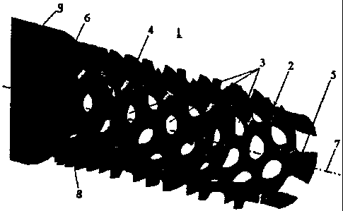
[0018] As shown in FIG. 1, the bone fixation element 1 may be in the form of a
hollow member 2 having a wall 4, a plurality of perforations 3 in the wall 4,
a front end 5
suitable for introduction into bone, a rear end 6 and a longitudinal axis 7.
Preferably, the
hollow member 2 may be in the form of a cylinder with an opened front end 5.
Moreover,
the wal14 may be a circumferential surface. It should, however, be understood
that those of
ordinary skill in the art will recognize many modifications and substitutions
which may be
made to various elements of the present invention.

-3-
NYJD: 1549228.2


CA 02491123 2004-12-29

[0019] As shown, at least a portion of the wall 4 may be provided with an
external
thread 8 for engaging bone or tissue. The thread 8 may be on a portion
adjacent the rear end
6. Additionally, the rear end 6 of the bone fixation element 1 may be provided
with means,
for example, an enlarged portion or conical head 9, which may be inserted
in/attached to a
bone plate (not shown).
[0020] Some of the advantages achieved by the bone fixation element 1 of the
present invention reside in the fact that the stiffness of the hollow member 2
may be
approximated to that of the surrounding bone. For example, the stiffness of
the bone
fixation element 1 may conform to the different stiffness present in a
vertebrae between the
corticalis, which has a modulus of elasticity of approximately 10,000 to
20,000 MPa, and
the spongiosa, which has a modulus of elasticity of approximately 100 to 5,000
MPa. In
addition, the bone fixation element 1 may have varying stiffness along its
length to conform
to conditions where the deflection and compression of the bone fixation
element 1 under
load is greater in the interior of the vertebrae than in the circumference or
edge region of the
vertebrae.
[0021] The stiffness of the bone fixation element 1 may change along the
longitudinal axis 7 by, for example, (1) reducing the thickness of the wall 4
of the bone
fixation element 1 in the region of transition between different portions of
bone (e.g.,
between the corticalis and the spongiosa) and/or (2) increasing the porosity
in the direction
of the front end 5 of the hollow member 2. A reduction in wall thickness
and/or an increase
in porosity may result in a decrease in stiffness. Conversely, an increase in
wall thickness
and/or a reduction in porosity may result in an increase in stiffness.
[0022] In the case of a thin-walled bone fixation element 1 with a circular
profile of
average radius Rm, the axial and polar areal moments of inertia (I,, and Ip),
as measurements
of the stiffness, may depend roughly on the wall thickness t and the porosity
p (perforation
area/total surface area) in the following way:

IX ~ n'Rm 't'p
IP 2=I1=RQ,3 t=p

[0023] In one embodiment, the stiffness of the bone fixation element 1 may
decrease
continuously from the rear end 6 to the front end 5. Moreover, the stiffness
of the rear third
of the hollow member 2 may be, for example, at least about 20% greater than
the stiffness
of the front third of the hollow member 2.

-4-
NYJD: 1549228.2


CA 02491123 2004-12-29

[0024] By parametric fmite element analysis, it was possible to establish that
the
stiffness of a circular section of the bone fixation element 1 depends
exponentially on the
wall thickness.
WcroSS smaon - t 2'7'43 is valid when tlR. ={ 0.4 ... 0.08 }

[0025] Thus, a reduction in wall thickness by 50% may lead to a reduction in
the
areal moments of inertia by approximately one half and may reduce the
stiffness of the cross
section to approximately 15%. Moreover, the wall thickness of the hollow
member 2 may
decrease continuously from the rear end 6 to the front end 5. In one
embodiment, the wall
thickness in the front third of the hollow member 2 may be, for example, at
least about 20%
less than the wall thickness in the rear third of the hollow member 2.
[0026] Furthermore, the porosity, as the ratio of the sum S of the n
perforation areas
to the total circumferential area M, may increase from the rear end 6 to the
front end 5. For
example, the porosity in the front third of the hollow member 2 may be at
least about 20%
greater than the porosity in the rear third of the hollow member 2. It should
be noted that
the smallest diameter of the n perforations 3 in the wall 4 of the hollow
member 2 may be,
for example, at least about 0.5 mm. In one embodiment, the maximum porosity
attainable
for the tightest possible arrangement of circular perforations 3 of the same
size may be
about 90%. However, in order to ensure the structural integrity of the wall 4
of the hollow
member 2, the porosity should not exceed about 85%.
[0027] In order to increase the porosity (decrease stiffness) of the bone
fixation
element 1, the number of perforations 3 andlor the area/size of the
perforations 3 may be
increased. For example, the number of perforations 3 per tenth of the height
of the hollow
member 2 may increase in the direction of the front end 5, while the area of
the individual
perforations 3 may remain constant (i.e., the frequency or density of the
perforations 3
increases from the rear end 6 to the front end 5). Alternatively, the number
of perforations 3
per tenth of the height of the hollow member 2 may remain constant in the
direction of the
front end 5, while the area of the individual perforations 3 may increase in
the direction of
the front end 5. Further, the partial view of the wall 4 of the hollow member
2, shown in
FIG. 2, illustrates how the area/size of the perforations 3 may increase
continuously from
the rear end 6 to the front end 5. In such an embodiment, the stiffness of the
hollow
member 2 may correspondingly decrease along the longitudinal axis 7 from the
rear end 6 to
the front end 5.
[0028] FIGS. 3 to 5 also illustrate various ways to change the porosity by
changing
the geometry of the perforations 3. Instead of round/circular perforations 3
(FIG. 2), the
-5-
NYJD: 1549228.2


CA 02491123 2004-12-29

perforations 3 may be any other shape including, for example, oval (FIG. 3),
square (FIG. 4)
or angular (e.g., triangular or quadrilateral) (FIG. 5). These perforations 3
may also
increase regularly in size from the rear end 6 to the front end 5. One purpose
of the hole
geometries may be to allow the stiffness of the bone fixation element 1 to
decrease from the
rear end 6 to the front end 5.
[0029) While the foregoing description and drawings represent the preferred
embodiments of the present invention, it will be understood that various
additions,
modifications and substitutions may be made therein without departing from the
spirit and
scope of the present invention as defmed in the accompanying claims. In
particular, it will
be clear to those skilled in the art that the present invention may be
embodied in other
specific forms, structures, arrangements, proportions, and with other
elements, materials,
and components, without departing from the spirit or essential characteristics
thereof. One
skilled in the art will appreciate that the invention may be used with many
modifications of
structure, arrangement, proportions, materials, and components and otherwise,
used in the
practice of the invention, which are particularly adapted to specific
environments and
operative requirements without departing from the principles of the present
invention. The
presently disclosed embodiments are therefore to be considered in all respects
as illustrative
and not restrictive, the scope of the invention being indicated by the
appended claims, and
not limited to the foregoing description.

-6-
NYJD: 1549228.2

Representative Drawing
A single figure which represents the drawing illustrating the invention.
Administrative Status

For a clearer understanding of the status of the application/patent presented on this page, the site Disclaimer , as well as the definitions for Patent , Administrative Status , Maintenance Fee  and Payment History  should be consulted.

Administrative Status

Title Date
Forecasted Issue Date 2010-06-01
(86) PCT Filing Date 2002-06-26
(87) PCT Publication Date 2004-01-08
(85) National Entry 2004-12-29
Examination Requested 2007-06-11
(45) Issued 2010-06-01
Deemed Expired 2016-06-27

Abandonment History

Abandonment Date Reason Reinstatement Date
2010-01-21 FAILURE TO PAY FINAL FEE 2010-02-12

Payment History

Fee Type Anniversary Year Due Date Amount Paid Paid Date
Application Fee $400.00 2004-12-29
Maintenance Fee - Application - New Act 2 2004-06-28 $100.00 2004-12-29
Maintenance Fee - Application - New Act 3 2005-06-27 $100.00 2005-06-14
Registration of a document - section 124 $100.00 2005-08-29
Maintenance Fee - Application - New Act 4 2006-06-27 $100.00 2006-06-06
Maintenance Fee - Application - New Act 5 2007-06-26 $200.00 2007-05-30
Request for Examination $800.00 2007-06-11
Maintenance Fee - Application - New Act 6 2008-06-26 $200.00 2008-05-13
Registration of a document - section 124 $100.00 2009-03-13
Maintenance Fee - Application - New Act 7 2009-06-26 $200.00 2009-06-01
Reinstatement - Failure to pay final fee $200.00 2010-02-12
Final Fee $300.00 2010-02-12
Maintenance Fee - Application - New Act 8 2010-06-28 $200.00 2010-05-13
Maintenance Fee - Patent - New Act 9 2011-06-27 $200.00 2011-05-11
Maintenance Fee - Patent - New Act 10 2012-06-26 $250.00 2012-05-10
Maintenance Fee - Patent - New Act 11 2013-06-26 $250.00 2013-05-08
Maintenance Fee - Patent - New Act 12 2014-06-26 $250.00 2014-05-15
Owners on Record

Note: Records showing the ownership history in alphabetical order.

Current Owners on Record
SYNTHES USA, LLC
Past Owners on Record
GOLDHAHN, JORG
SCHNEIDER, ERICH
SEEBECK, JORN
SYNTHES (U.S.A.)
Past Owners that do not appear in the "Owners on Record" listing will appear in other documentation within the application.
Documents

To view selected files, please enter reCAPTCHA code :


To view images, click a link in the Document Description column. To download the documents, select one or more checkboxes in the first column and then click the "Download Selected in PDF format (Zip Archive)" or the "Download Selected as Single PDF" button.

List of published and non-published patent-specific documents on the CPD .

If you have any difficulty accessing content, you can call the Client Service Centre at 1-866-997-1936 or send them an e-mail at CIPO Client Service Centre.


Document
Description 
Date
(yyyy-mm-dd) 
Number of pages   Size of Image (KB) 
Abstract 2004-12-30 1 17
Claims 2004-12-30 3 101
Drawings 2004-12-30 2 50
Claims 2010-02-12 5 180
Representative Drawing 2004-12-29 1 22
Description 2004-12-29 6 242
Drawings 2004-12-29 3 45
Claims 2004-12-29 3 82
Abstract 2004-12-29 2 88
Cover Page 2005-03-09 1 49
Description 2004-12-30 6 349
Description 2009-03-23 6 345
Claims 2009-03-23 3 104
Cover Page 2010-05-06 1 39
Representative Drawing 2010-05-06 1 8
Prosecution-Amendment 2010-02-12 7 224
PCT 2004-12-29 8 286
Assignment 2004-12-29 3 91
Prosecution-Amendment 2004-12-29 14 575
Correspondence 2010-03-30 1 18
PCT 2004-12-29 4 156
Correspondence 2005-03-05 1 25
Assignment 2005-08-29 3 91
Prosecution-Amendment 2007-06-11 1 39
Prosecution-Amendment 2008-09-23 2 68
Prosecution-Amendment 2009-03-23 7 261
Assignment 2009-03-13 11 620
Prosecution-Amendment 2010-02-12 1 57