Note: Descriptions are shown in the official language in which they were submitted.
CA 02491293 1997-04-23
Method And Annaratus For Remote Control Of Multilateral Wells
This is a divisional application of Canadian Patent Application 2,252,728
filed on
April 23, 1997.
The present invention relates to subsurface well completion equipment and,
more
particularly, to methods and related apparatus for remotely controlling fluid
recovery
from multiple laterally drilled wellbores. Tt should be understood that the
expression "the
invention" and the like encompasses the subject matter of both the parent and
the
divisional applications.
Hydrocarbon recovery volume from a vertically drilled well can be increased by
io drilling additional wellbores from that same well. For example, the fluid
recovery rate
and the well's economic life can be increased by drilling a horizontal
interval from a main
wellbore radially outward into one or more formations. Still further increases
in recovery
and well life can be attained by drilling multiple horizontal intervals into
multiple
formations. Once the multilateral wellbores have been drilled and completed
there is a
need for the recovery of fluids from each wellbore to be individually
controlled.
Currently, the control of the fluid recovery from these multilateral wellbores
has been
limited in that once a lateral wellbore has been opened it is not possible to
selectively
close off and/or reopen the lateral wellbores without the need for the use of
additional
equipment, such as wireline units, coiled tubing units and workover rigs.
2o The need for selective fluid recovery is important in that individual
producing
intervals usually contain hydrocarbons that have different physical and
chemical
properties and as such may have different unit values. Co-mingling a valuable
and
desirable crude with one that has, for instance, a high sulfur content would
not be
commercially expedient, and in some cases is prohibited by governmental
regulatory
authorities. Also, because different intervals inherently contain differing
volumes of
hydrocarbons, it is highly probable that one interval will deplete before the
others, and
will need to be easily and inexpensively closed off from the vertical wellbore
before the
other intervals.
CA 02491293 1997-04-23
2
The use of workover rigs, coiled tubing units and wireline units are
relatively
inexpensive if used onshore and in typical oilFeld locations; however,
mobilizing these
resources for a remote offshore well can be very expensive in terms of actual
dollars
spent, and in terms of lost production while the resources are being moved on
site. In
the case of subsea welts (where no surface platform is present), a drill ship
or workover
vessel mobilization would be required to merely open/close a downhole wellbore
valve.
The following patents disclose the current multilateral drilling and
completion
techniques. U.S. Patent 4,402,551 details a simple completion method when a
lateral
wellbore is drilled and completed through a bottom of an existing traditional,
vertical
wellbore. Control of production fluids from a well completed in this manner is
by
traditional surface weUhead valuing methods, since improved methods of
recovery from
only one lateral and one interval is disclosed. The importance of this patent
is the
recognition of the role of orienting and casing the lateral wellbore, and the
care taken
in sealing the juncture where the vertical borehole interfaces with the
lateral wellbore.
U.S. Patent 5,388,648 discloses a method and apparatus for sealing the
juncture
between one or more horizontal wells using deformable sealing means. This
completion
method deals primarily with completion techniques prior to insertion of
production
tubing in the well. While it does address the penetration of multiple
intervals at different
depths in the well, it does not offer solutions as to how these different
intervals may be
selectively produced.
U.S. Patent 5,337,808 discloses a technique and apparatus for selective multi-
zone vertical and/or horizontal completions. This patent illustrates the need
to
selectively open and close individual intervals in wells where multiple
intervals exist, and
discloses devices that isolate these individual zones through the use of
workover rigs.
CA 02491293 1997-04-23
3
U.S. Patent 5,447,201 discloses a well completion system with selective remote
surface control of individual producing zones to solve some of the above
described
problems. Similarly, U.S. Patent 5,411,085, commonly assigned hereto,
discloses a
production completion system which can be remotely manipulated by a
controlling
means extending between downhole components and a panel located at the
surface.
Each of these patents, while able to solve recovery problems without a
workover rig,
fails tv address the unique problems associated with multilateral wells, and
teaches only
recovery methods from multiple interval wells. A multi-lateral well that
requires reentry
remediation which was completed with either of these techniques has the same
problems
as before: the production tubing would have to be removed, at great expense,
to re-enter
the Lateral for remediation, and reinserted in the well to resume production.
U.S. Patent 5,44,131 discloses a method for completing mufti-lateral wells and
maintaining selective re-entry into the lateral wellbores. This method allows
for re-entry
remediation into horizontal laterals, but does not address the need to
remotely
manipulate downhole completion accessories from the surface without some
intervention
technique. In this patent, a special shifting tool is required to be inserted
in the well on
coiled tubing to engage a set of ears to shift a flapper valve to enable
selective entry to
either a main wellbore or a lateral. To accomplish this, the well production
must be
halted, a coiled tubing company called to the jobs site, a surface valuing
system attached
to the wellhead must be removed, a blow out preventer must be attached to the
wellhead, a coiled tubing injector head must be attached to the blow out
preventer, and
the special shifting tool must be attached to the coiled tubing; all before
the coiled tubing
can be inserted in the well.
U.S. Patent 2,304,303 describes a flow control assembly comprising a body
CA 02491293 1997-04-23
3A
having a central bore extending therethrough and having means on one end for
interconnection to a well tubing. A selectively operable access door is
provided in the
body for alternately permitting and preventing a service tool from laterally
exitingr the
body thereth~ough.
There is a need for a system to allow an operator standing at a remote control
CA 02491293 1997-04-23
4
panel to selectively permit and prohibit flow from multiple lateral well
branches drilled
from a common central wellbore without having to resort to common intervention
techniques. Alternately, there is a need for an operator to selectively open
and close a
valve to implement re-entry into a lateral branch drilled from the common
wellbore.
There is a need for redundant power sources to assure operation of these
automated
downhole devices, should otte err more power sources fail. Finally, there is a
need for
fail safe mechanical recovery tools, should these automated systems become
inoperative.
The present invention has been contemplated to overcome the foregoing
deficiencies and meet the above described needs. Specifically, the present
invention is
a system to recover fluids from a well that has either multiple intervals
adjacent to a
central wellbore or has multiple lateral wellbores which have been drilled
From a central
wellbore into a plurality of intervals in proximity to the central wellbore.
More specifically, the present invention provides a method of remotely
accessing
a first lateral wellbore and a second lateral wellbore for remediation
purposes, the first
and second lateral wellbores extending from a central wellbore, the method
comprising
the steps of connecting a first and a second selectively operable lateral
access assembly to
a tubing string, the first lateral access assembly having a first lateral
access door, and the
second lateral access assembly having a second lateral access door, locating
and orienting
the tubing string in the central wellbore with the first lateral door adjacent
the first lateral
wellbore and the second lateral access door adjacent the second lateral
wellbore, closing
the first lateral access door, opening the second lateral access door, setting
a selective
orienting deflector tool in the second lateral access assembly adjacent the
second lateral
wellbore, and using the deflector tool to guide a service tool into the second
lateral
wellbore.
CA 02491293 1997-04-23
4a
The present invention also provides a lateral access assembly for
interconnection
to a well tubing, the well tubing being disposed in a central wellbore having
at least one
lateral wellbore extending therefrom, the lateral access assembly comprising a
body
having a central bore extending therethrough, a communication conduit
connecting a
rotary motor disposed within the body to a surface control panel, and a
lateral access door
disposed in the central bore, connected to the rotary motor, and having an
open position
to permit entry of a service tool into the lateral wellbore and a closed
position to restrict
entry of the service tool into the lateral wellbore, whereby power is
transmitted through
the communication conduit to the rotary motor to rotate the lateral access
door to its
closed and open positions.
In accordance with the present invention an improved method is disclosed to
allow selective recovery from any of a well's intervals by remote control from
a panel
located at the earth's surface. This selective recovery is enabled by any
number of
well known controlling means, i.e. by electrical signal, by hydraulic signal,
by fiber
optic signal, or any combination thereof, such combination comprising a
piloted signal
of one of these controlling means to operate another. Selective control of
producing
formations would preclude the necessity of expensive, but commonly practised
workover techniques to change producing zones, such as: ( 1 ) standard tubing
conveyed intervention, should a production tubing string need to be removed or
deployed in the well, or (2) should a work string need to be utilized for
remediation,
and would also reduce the need and frequency of either (3) coiled tubing
remediation
or (4) wireline procedures to enact a workover, as well.
CA 02491293 1997-04-23
Preferably, these controlling means may be independent and redundant, to
assure
operation of the production system in the event of primary control failure;
and may be
operated mechanically by the aforementioned commonly practised workover
techniques
to change producing zones, should the need arise.
5 In a preferred embodiment, a well comprising a central casing adjacent at
least
two hydrocarbon producing formations is cemented in the earth. A production
tubing
string located inside the casing is fixed by any of several well known
completion
accessories. Packers, which are well known to those skilled in the art,
straddle each of
the producing formations and seal an annulus, thereby preventing the produced
wellbore
fluids from flowing to the surface in the annulus. A surface activated flow
control valve
with an annularly openable orifice, located between the packers, may be opened
or
closed upon receipt of a signal transmitted from the control panel, with each
producing
formation, between a wellhead at the surface and the lowermost producing
formation,
having a corresponding flow control valve.. With such an arrangement, any
formation
I S can be produced by opening its corresponding flow control valve and
closing all other
flow control valves in the wellbore. Thereafter, co-mingled flow from
individual
formations is prevented, or allowed, as is desired by the operations personnel
at the
surface control panel. Further, the size of the annularly openable orifice can
be adjusted
from the surface control panel such that the rate of flow of hydrocarbons
therefrom can
be adjusted as operating conditions warrant.
Should conditions in one or more of the laterals warrant re-entry by either
coiled
tubing or other well known methods, a rotating lateral access door directly
adjacent to
and oriented toward each lateral in the well can be selectively opened, upon
receipt of
a signal from the control panel above. The access door, in the open position,
directs
CA 02491293 1997-04-23
G
service toots inserted into the central wellbore into the selected lateral.
Closure of the
access door, prevents entry of service tools running in the central wellbore
from entering
laterals that were not selected for remediation.
In accordance with this preferred embodiment, should either the flow control
S valve or the rotating lateral access door lose communication with the
surface control
panel, or should either device become otherwise inoperable by remote control,
mechanical manipulation devices that may be deployed by coiled tubing are
within the
scope of this invention and are disclosed herein.
The features and advantages of the present invention will be appreciated and
understood by those skilled in the art from the following detailed description
and
drawings., in which:
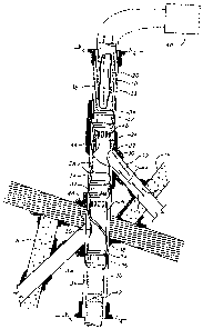
Figure I is a schematic representation of a wellbore completed using one
preferred embodiment of the present invention.
Figures 2 A-G taken together form a longitudinal section of one preferred
embodiment of an apparatus of the present invention with a lateral access door
in the
open position.
Figures 3 A-H taken together form a longitudinal section of the apparatus of
Figure 2 with a work string shown entering a lateral, and a longitudinal
section of a
selective orienting deflector tool located in position.
Figures 4 A-B illustrate two cross sections of Figure 3 taken along line "A-
A",
without the service tools as shown therein. Figure 4-A depicts the cross
section with a
rotating lateral access door shown in the open position, while Figure 4-B
depicts the
cross section with the rotating lateral access door shown in the closed
position.
Figure 5 illustrates a cross sections of Figure 3 taken along line "B-B",
without
CA 02491293 1997-04-23
7
the service tools as shown therein.
Figure 6 illustrates a cross section of Figure 3 taken along line "D-D", and
depicts a locating, orienting and locking mechanism for anchoring the
multilateral flew
control system to the casing.
Figure 7 illustrates a longitudinal section of Fgure 5 taken along line "C-C",
and
depicts an opening of the rotating lateral access door shown in the open
position, and
the sealing mechanism thereof.
Figure 8 illustrates a cross section of Figure 3 taken along line "E-E", and
depicts an orienting and locking mechanism for a selective orienting deflector
tool and
is located therein.
'The present imrention is a system for remotely controlling multilateral
wells, and
will be described in conjunction with its use in a well with three producing
formations
for purposes of illustration only. One skilled in the art will appreciate many
differing
applications of the described apparatus. It should be understood that the
described
invention may be used in multiples for any well with a plurality of producing
formations
where either multiple lateral branches of a well are present, or multiple
producing
formations that are conventionally completed, such as by well perforations or
uncased
open hole, or by any combination of these methods. Specifically, the apparatus
of the
present invention includes enabling devices for automated remote control and
access of
multiple formations in a central wellbore during production, and allow work
and time
saving intervention techniques when remediativn becomes necessary.
For the purposes of this discussion, the terms "upper" and "lower", "up hole"
and
"downhole", and "upwardly" and downwardly" are relative terms to indicate
position and
direction of movement in easily recognized terms. Usually, these terms are
relative to
CA 02491293 1997-04-23
8
a Line drawn from an upmost position at the surface to a point at the center
of the earth,
and would be appropriate for use in relatively straight, vertical wellbores.
However,
when the wellbore is highly deviated, such as from about 60 degrees from
vertical, or
horizontal these terms do not make sense and therefore should not be taken as
limitations. These terms are only used for ease of understanding as an
indication of what
the position or movement would be if taken within a vertical wel)bore.
Referring now to Figure I, a substantially vertical wellbore 10 is shown with
an
upper lateral wellbore 12 and a lower lateral wellbore 14 drilled to intersect
an upper
producing zone 16 and an intermediate producing zone 18, as is well known to
those
skilled in the art of multilateral drilling. A production tubing 20 is
suspended inside the
vertical wellbore 10 for recovery of fluids to the earth's surface. Adjacent
to an upper
lateral well junction 22 is an upper fluid flow control apparatus 24 of the
present
invention while a lower fluid flow control apparatus 26 of the present
invention is
located adjacent to a lower lateral well junction 28. Each fluid flow control
apparatus
24 and 26 are the same as or similar in configuration. In one preferred
embodiment, the
fluid flow control apparatus 24 and 26 generally comprises a generally
cylindrical
mandrel body having a central longitudinal bore extending therethrough, with
threads
or other connection devices on one end thereof for interconnection to the
production
tubing 20. A selectively operable lateral access door is provided in the
mandrel body for
alternately permitting and preventing a service tool from laterally exiting
the body
therethrough and into a lateral wellbore. 1n addition, in one preferred
embodiment, a
selectively operable flow control valve is provided in the body for regulating
fluid flow
between the outside of the body and the central bore.
In the fluid flow control apparatus 24 a lateral access door 30 comprises an
CA 02491293 1997-04-23
9
opening in the body and a door or plug member. The door may be moved
longitudinally
or radially, and may be moved by one or more means, as will be described in
more detail
below. In Figure 1 the door 30 is shown oriented toward its respective
adjacent lateral
wellbore_ A pair of permanent or retrievable elastomeric packers 32 are
provided on
separate bodies that are connected by threads to the mandrel body or,
preferably, are
connected as part of the mandrel body. The packers 32 are used to isolate
fluid flow
between producing zones 16 and 18 and provide a fluidie seal thereby
preventing co-
mingling flow oFproduced fluids through a wellbore annulus 34. A lowermost
packer
36 is provided to anchor the production tubing 20, and to isolate a lower most
producing zone (not shown) from the producing zones 16 and 18 above. A
communication conduit or cable or conduit 38 is shown extending from the fluid
flow
control apparatus 26, passing through the isolation packers 32, up to a
surface control
panel 40. A tubing plug 42, which is well known, may be used to block flow
from the
lower most producing zone (not shown) into the tubing 20.
A well with any multiple of producing zones can be completed in this fashion,
and a large number of flow configurations can be attained with the apparatus
of the
present invention. For the purposes of discussion, all these possibilities
will not be
discussed, but remain within the scope of the present invention. In the
configuration
shown in Figure 1, the production tubing 20 is plugged at the lower end by the
tubing
plug 42, the lower fluid flow control apparatus 26 has a flow control valve is
shown
closed, and the upper fluid flow control apparatus 24 is shown with its flow
control
valve in the open position. This production configuration is managed by an
operator
standing on the surface at the control panel 40, and can be changed therewith
by
manipulation of the controls on that panel. In this production configuration,
flow From
CA 02491293 1997-04-23
all producing formations is blocked, except from the upper producing zone 16.
Hydrocarbons 44 present therein will flow from the formation 16, through the
upper
lateral wellbore 12, into the annulus 34 of the vertical wellbore 10, into a
set of ports 46
in the mandrel body and into the interior of the production tubing 20. From
there, the
5 produced hydrocarbons move to the surface.
Turning now to Figures 2 A-G, which, when taken together illustrate the fluid
flow control apparatus 24. An upper connector 48 is provided on a generally
cylindrical
mandrel body SO for sealable engagement with the production tubing 20. An
elastomeric
packing element 52 and a gripping device 54 are connected to the mandrel body
50. A
10 first communication conduit 56, preferably, but not limited to electrical
communication,
and a second communication conduit 58, preferably, but not limited to
hydraulic control
communication, extend from the eartlx's surface into the mandrel 50. The first
56 and
second 58 communication conduits communicate their respective signals to/from
the
earth's surface and into the mandrel 50 around a set of bearings 6d to a slip
joint 62.
The electrical communication conduit or cable 56 connects at this location,
while the
hydraulic communication conduit 58 extends therepast. The bearings 60 reside
in a
rotating swivel joint 64, which allows the mandrel body 50 and its lateral
access door 30
to be rotated relative tubing 20, to ensure that the lateral access door 30 is
properly
aligned with the lateral wellbore. Further, the electrical communication
conduit or cable
SG communicates with a first pressure transducer 6G to monitor annulus
pressure, a
temperature and pressure sensor 68 to monitor temperature and hydraulic
pressure,
and/or a second pressure transducer 70 to monitor tubing pressure. Signals
from these
transducers are communicated to the control panel 40 on the surface so
operations
personnel can make informed decisions about downhole conditions.
CA 02491293 1997-04-23
I1
In this preferred embodiment, the electrical communication conduit or cable
also
communicates with a solenoid valve 72, which selectively controls the flow of
hydraulic
fluid from the hydraulic communication conduit 58 to an upper hydraulic
chamber 74,
across a movable piston 76, to a lower hydraulic chamber 78. The differential
pressures
in these two chambers 74 and 78 move the operating piston 76 a sleeve
extending
therefrom in relation to an annularly openable port or orifice 80 in the
mandrel body 50
to allow hydrocarbons to flow from the annulus 34 to the tubing 20. Further,
the rate
of fluid flow can be controlled by adjusting the relative position of the
piston 76 through
the use of a flow control position indicator 82, which provides the bperator
constant and
instantaneous feedback as to the size of the opening selected.
In some instances, however, normal operation of the flow control valve may not
be possible for any number of reasons. An alternate and redundant method of
opening
or closing the flow control valve and the annulatly operable orifice 80 uses a
coiled
tubing deployed shilling tool 84 landed in a profile in the internal surface
of the mandrel
I S body 50. Pressure applied to this shifting tool 84 is sufficient to move
the flow control
valve to either the open or closed positions as dictated by operational
necessity, as can
be understood by those sltilled in the art.
The electrical communication conduit or cable 58 further communicates
electrical
power to an high torque rotary motor 88 which rotates a pinion gear 90 to
rotate a
lateral access plug member or door 92. This rotational force opens and closes
the
rotating lateral access door 92 should entry into the lateral wellbore be
required. In some
instances, however, normal operation rotating lateral access door 92 may not
be possible
for any number of reasons. An alternate, and redundant method of opening the
rotating
lateral access door 92 is also provided wherein a coiled tubing deployed
rotary tool 94
CA 02491293 1997-04-23
12
is shown located in a lower profile 9G in the interior of the mandrel body S0.
Pressure
applied to this rotary tool 94 is sufficient to rotate the rotating lateral
access door 92 to
either the open or closed positions as dictated by operational necessity, as
would be well
known to those skilled in the art.
S When the fluid flow apparatus 24 and 26 are set within the wellbore the
depth
and azimutha) orientation is controlled by a spring loaded, selective
orienting key 98 on
the mandrel body SO which interacts with an orienting sleeve within a casing
nipple,
which is well known to those skilled in the art. Isolation of the producing
zone is
assured by the second packing element S2, and the gripping device S4, both
mounted on
IO the mandrel body S0, where an integrally formed lower connector 100 for
sealable
engagement with the production tubing 20 resides.
Referring now to Figures 3 A-H, which, when taken together illustrate the
upper
fluid flow control apparatus 24, set and operating in a well casing 102. In
this
embodiment, an upper valve seat 104 on the mandrel SO and a lower 106 valve
seat on
l S the piston 7G are shown seatably engaged, thereby blocking fluid flow. The
lateral
access door 92 is in the form of a plug member that is formed at an angle to
facilitate
movement of service tools into and out of the lateral. Once so opened, a
coiled tubing
108, or other well known remediation tool, can be easily inserted in the
lateral wellbore.
For purposes of illustration, a flexible tubing member I 10 is shown attached
to the
20 coiled tubing I08, which is in turn, attached to a pulling tool 112, that
is being inserted
in a cased lateral I 14.
A selective orienting deflector tool 116 is shown set in a profile I 18 formed
in
the interior surface of the upper fluid flow control apparatus 24. The
deflector tool 116
is located, oriented, and held in position by a set of locking keys 120, which
serves to
CA 02491293 1997-04-23
13
direct any particular service tool inserted in the vertical wellbore 10, into
the proper
cased lateral 114.
The depth and azimuthal orientation of the assembly as hereinabove discussed
is controlled by a spring loaded, selective orienting key 98, which sets in a
casing profile
S 122 of a casing nipple 124. Isolation of the producing zone is assured by
the second
packing element 52, and the gripping device 54, both mounted on the central
mandrel
50.
Figure 4 A-B is a cross section taken at "A-A" of Figure 3-D and represents a
view of the top of the rotating lateral access door 92. Figure 4-A illustrates
the
relationship of the well casing 102, the cased lateral 114, the pinion gear
90, and the
rotating lateral access door 92, shown in the open position. Figure 4-B
illustrates the
relationship of the well casing 102, the cased lateral 114, the pinion gear
90, and the
rotating lateral access door 92, shown in the closed position. Referring now
to Figure
5, which is a cross section taken at "B-B" of Figure 3-E, and is shown without
the
1 S flexible tubing member 110 in place, at a location at the center of the
intersection of the
cased lateral 114, and the well casing 102. This diagram shows the rotating
lateral
access door 92 in the open position, and a door seal 126. Figure 6 is a cross
section
taken at "D-D" of Figure 3-F and illustrates in cross section the manner in
which the
selective orienting key 98 engages the casing nipple 124 assuring the assembly
described
herein is located and oriented at the correct position in the well.
Turning now to Figure 7, which is a longitudinal section taken at "C-C" of
Figure S. This diagram primarily depicts the manner in which the door seal 126
seals
around an elliptical opening 128 formed by the intersection of the cylinders
formed by
the cased lateral 114 and the rotating lateral access door 92. This view
clearly shows
CA 02491293 1997-04-23
14
the bevel used to ease movement of service tools into and out of the cased
lateral I 14.
The final diagram, Figure 8, is a cross section taken at "E-E" of Figure 3-E.
This shows
the relationship of the casing nipple 124, the orienting deflector tool 116,
the profile 118
formed in the interior surface of the upper fluid flow control apparatus 24,
and how the
locking keys 120 interact with the profile 118.
In a typical operation, the oil well production system of the present
invention is
utilized in wells with a plurality of producing formations which may be
selectively
produced. Referring once again to Figure 1, if it were operationally desirable
to produce
from the upper producing zone 16 without co-mingling the flow with the
hydrocarbons
from the other formations; first a tubing plug 42 would need to be set in the
tubing to
isolate the lower producing zone (not shown). The operator standing at the
control
panel would then configure the control panel 40 to close the lower fluid flow
control
apparatus 26, and open the upper fluid flow control apparatus 24. Both
rotating lateral
access doors 30 would be configured closed. In this configuration, flow is
blocked from
both the intermediate producing zone 18, and the lower producing none and
hydrocarbons from the upper producing zone would enter the upper lateral 12,
flow into
the annulus 34, tluough the set of ports 46 on the upper fluid flow control
apparatus 24;
and into the production tubing 20, which then moves to the surface. Different
flow
regimes can be accomplished simply by altering the arrangement of the open and
closed
valves from the control panel, and moving the location of the tubing plug 42.
The
necessity of the tubing plug 42 can be eliminated by utilizing another flow
control valve
to meter flow from the lower formation as well.
When operational necessity dictates that one or more of the laterals requires
re-
entry, a simple operation is all that is necessary to gain access therein. For
example,
CA 02491293 1997-04-23
assume the upper lateral 12 is chosen for remediation. The operator at the
remote
control panel 40 shuts all flow control valves, assures that all rotating
lateral access
doors 30 are closed except the one adjacent the upper lateral 12, which would
be
opened. If the orienting deflector tool 116 is not installed, it would become
necessary
5 to install it at this time by any of several well known methods. In all
probability,
however, the deflector tool 116 would already be in place. Entry of the
service tool in
the lateral could then be accomplished, preferably by coiled tubing or a
flexible tubing
TM
such as CO-FLE70P brand pipe, because the production tubing 20 now has an
opening
oriented toward the lateral, and a tool is present to deflect tools running in
the tubing
10 into the desired lateral. Production may be easily resumed by configuring
the flow
control valves as before.
Whereas the present invention has been described in particular relation to the
drawings attached hereto, it should be understood that other and further
modifications,
apart from those shown or suggested herein, may be made within the scope of
the
I S present invention as defined in the appended claims.