Language selection

Search

Patent 2491405 Summary

Third-party information liability

Some of the information on this Web page has been provided by external sources. The Government of Canada is not responsible for the accuracy, reliability or currency of the information supplied by external sources. Users wishing to rely upon this information should consult directly with the source of the information. Content provided by external sources is not subject to official languages, privacy and accessibility requirements.

Claims and Abstract availability

Any discrepancies in the text and image of the Claims and Abstract are due to differing posting times. Text of the Claims and Abstract are posted:

  • At the time the application is open to public inspection;
  • At the time of issue of the patent (grant).
(12) Patent: (11) CA 2491405
(54) English Title: DEVICE FOR CHANGING THE CLOTHING OF A PAPER MACHINE
(54) French Title: CHANGEUR D'HABILLAGE DE MACHINE A PAPIER
Status: Granted and Issued
Bibliographic Data
(51) International Patent Classification (IPC):
  • D21F 7/00 (2006.01)
  • D21G 9/00 (2006.01)
(72) Inventors :
  • MAUSSER, WILHELM (Austria)
  • SCHADLER, GERALD (Austria)
(73) Owners :
  • ANDRITZ AG
(71) Applicants :
  • ANDRITZ AG (Austria)
(74) Agent: MARKS & CLERK
(74) Associate agent:
(45) Issued: 2012-07-17
(22) Filed Date: 2005-01-04
(41) Open to Public Inspection: 2005-07-13
Examination requested: 2009-02-18
Availability of licence: N/A
Dedicated to the Public: N/A
(25) Language of filing: English

Patent Cooperation Treaty (PCT): No

(30) Application Priority Data:
Application No. Country/Territory Date
A 29/2004 (Austria) 2004-01-13

Abstracts

English Abstract

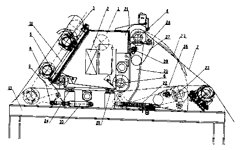
The invention relates to a device for changing the clothing of a paper machine, particularly a tissue machine, for example a TAD (through-air drying) machine, with a number of deflection rolls 3, 4, 5, 6 and at least one cleaning device 27, 28, 29 for the machine clothing. Levers 9, 20 are provided on either side of the machine clothing 7, where these levers hold at least one deflection roll 3, 4 and can be pivoted from an operating position to a machine clothing changing position. Thus, the time and the number of personnel required to change the machine clothing are reduced substantially.


French Abstract

La présente invention porte sur un dispositif servant à changer l'habillage d'une machine à papier, notamment une machine à papiers-mouchoirs (p. ex. une sécheuse à air) munie d'un certain nombre de cylindres à déflexion (3, 4, 5, 6) et d'au moins un dispositif de nettoyage (27, 28, 29) pour l'habillage de la machine. Des leviers (9, 20) sont installés de chaque côté de l'habillage de la machine (7). Ceux-ci y supportent au moins un cylindre à déflexion (3, 4) et peuvent pivoter sur leur axe pour passer d'une position de fonctionnement à une position de changement d'habillage de la machine. Ainsi, le nombre d'employés requis pour procéder au changement d'habillage et le temps nécessaire à cette opération s'en trouvent sensiblement réduits.

Claims

Note: Claims are shown in the official language in which they were submitted.

The embodiments of the invention in which an exclusive property or
privilege is claimed are defined as follows:
1. A device for changing a clothing of a paper machine, with a number of
deflection rolls and at least one cleaning device for the machine clothing,
comprising first fevers and second levers being provided on either side of the
machine clothing, wherein the first and second levers hold at least one
deflection
roll and can be pivoted from an operating position to a machine clothing
changing position, with the machine clothing cleaning device comprising
showers.
2. The device according to claim 1, wherein the position of the deflection
roll
or roll(s) for changing machine clothing is such that the clothing can be
inserted
into the paper machine virtually horizontally.
3. The device according to claim 1 or 2, wherein the deflection roll is a
tensioning roll.
4. The device according to claim 3, wherein the tensioning roll is suitable
for
connecting via a bearing housing to the levers arranged on either side of the
machine clothing when the tensioning device is in a final position at zero
tension.
5. The device according to claim 1 or 2, wherein at least two levers mounted
on either side if the machine clothing being connected to one another via a
splash protection tray.
6. The device according to claim 5, wherein the splash protection tray and
cleaning showers mounted in it being suitable for pivoting into the machine
clothing changing position together with the deflection roll using the levers
mounted on either side of the clothing.
7. The device according to any one of claims 1 to 6, wherein the first levers
and the second levers are connected to lifting elements.
4

8. The device according to claim 7, wherein the lifting elements are hydraulic
lifting elements.
9. The device according to claim 7, wherein the lifting elements are electro-
mechanical lifting elements.

Description

Note: Descriptions are shown in the official language in which they were submitted.


CA 02491405 2005-01-04
DEVICE FOR CHANGING THE CTATHING OF A PAPER MACHINE
The invention relates to a device for changing the clothing of a paper
machine, particularly a tissue machine, for example a TAD (through-air
drying) machine, with a number of deflection rolls and at least one cleaning
device for the machine clothing.
The equipment currently used has the disadvantage that changing of the
machine clothing takes a long time, is labour-intensive, and requires
additional resources, e.g. machine room cranes, which thus are not
available for other maintenance work, such as roll changing, routine
headbox maintenance, etc., during changing of machine clothing. The
machine clothing mentioned here relates to wires, felts, or similar clothing
elements.
The aim of the invention is thus to simplify changing of machine clothing in
such a way that the changing time is shortened, the number of persons
required is reduced, and no auxiliary equipment is needed that is not
integrated into the machine design.
The invention is thus characterised by levers being provided, mounted on
either side of the machine clothing, where these levers hold at least one
deflection roll and can be pivoted from an operating position to a machine
clothing changing position. As a result, external lifting gear, such as
machine cranes, are no longer needed and can be used for other
purposes. In addition, there is no longer any need for the complicated
procedure to remove the deflection roll(s), nor to store them outside the
machine. This substantially reduces the time required for changing the
machine clothing. In addition, the invention considerably improves safety
of the operating personnel (no rolls swinging out of the machine).
If the position of the deflection roll(s) for changing machine clothing is
such
that the clothing can be inserted into the paper machine virtually
horizontally, less personnel are required because the clothing no longer
has to be pre-folded. This is a particular advantage with the stiff TAD
wires.
1

CA 02491405 2011-07-28
The invention is used to advantage if the deflection roll is a tensioning
roll,
where the tensioning roll can be suitable for connecting via the bearing
housing to the levers arranged on either side of the machine clothing when
the tensioning device is in the final position at zero tension. Using the
tensioning roll, the machine clothing can be reduced to zero tension and
the lever then used to move the tensioning roll into the machine clothing
changing position, at which the machine clothing can be inserted virtually
horizontally.
A favourable further development of the invention is characterised by at
least two levers mounted on either side of the machine clothing being
connected to one another via a splash protection tray, where the splash
protection tray and any cleaning showers mounted in it can be pivoted into
the machine clothing changing position together with the deflection roll
using the levers mounted on either side of the machine clothing. Thus,
such machine parts as the splash protection tray and cleaning showers can
be lowered together at the same time and need not be dismantled
separately for this purpose.
A favourable embodiment of the invention is characterised by the levers
being connected to the lifting elements, where the lifting elements can be
operated hydraulically, e.g. hydraulic cylinders or electro-mechanical lifting
elements, i.e. electrically driven lifting spindles.
In one aspect:, the invention provides a device for changing a clothing of a
paper machine, with a number of deflection rolls and at least one cleaning
device for the machine clothing, comprising first levers and second levers
being provided on either side of the machine clothing wherein the first and
second levers hold at least one deflection roll and can be pivoted from an
operating position to a machine clothing changing position, with the
machine clothing cleaning device comprising showers.
The invention will now be described in examples and referring to the
drawings, where the Figure shows one variant of the invention.
The invention is used in the vicinity of the machine clothing cleaning
2

CA 02491405 2011-07-28
device 1 in a paper machine, which essentially comprises a cantilevering
support structure 2, a tensioning roll for the machine clothing 3, a
deflection
roll 4, as well as two further guide rolls 5, 6 for the machine clothing, and
various cleaning devices, i.e. showers, suction boxes and cleaning doctors.
2a

CA 02491405 2005-01-04
When threading in new machine clothing 7 with endless woven design, the
tensioning roll 3 is run into the shortest tensioning position 8. In this
position, two levers 9 on the operating and drive sides of the paper
machine are moved up against the roll bearing at roll 3 using an hydraulic
cylinder or worm gear screw jacks 10 and bolted to the bearing. After this,
the connection between the roll bearing and the guide blocks 11 of the
tensioning device is detached. The tensioning roll 3 can now be placed on
the machine frame 13.
Then, the levers 20 that support the deflection roll 4 are detached from the
supporting structure 2 on the operating and drive sides by undoing the
connections 21 (e.g. bolted connections). After disconnecting all of the
showers and suction devices on the drive side, the levers 20 are lowered
with the aid of lifting elements 22 in the direction indicated by the arrow 23
onto the machine frame 13 together with the roll 4 and all of the showers
and water collecting trays 27 secured to the roll.
After placing the two rolls 3 and 4 onto the machine frame 13, the
intermediate pieces 24 and 25 in the frame are removed from the
supporting structure 2 using a cantilever device. The new machine
clothing 26 can now be inserted easily, in a virtually horizontal position and
without counter-bending, through the openings thus created on the
operating side of the machine. The type of roll positioning according to the
invention also creates much more excess length in the clothing element,
which makes it easier to insert it into the remaining part of the machine.
This too causes a reduction in the time required for changing endless
woven machine clothings.
3

Representative Drawing
A single figure which represents the drawing illustrating the invention.
Administrative Status

2024-08-01:As part of the Next Generation Patents (NGP) transition, the Canadian Patents Database (CPD) now contains a more detailed Event History, which replicates the Event Log of our new back-office solution.

Please note that "Inactive:" events refers to events no longer in use in our new back-office solution.

For a clearer understanding of the status of the application/patent presented on this page, the site Disclaimer , as well as the definitions for Patent , Event History , Maintenance Fee  and Payment History  should be consulted.

Event History

Description Date
Common Representative Appointed 2019-10-30
Grant by Issuance 2012-07-17
Inactive: Cover page published 2012-07-16
Inactive: Final fee received 2012-05-07
Pre-grant 2012-05-07
Notice of Allowance is Issued 2011-12-19
Letter Sent 2011-12-19
Notice of Allowance is Issued 2011-12-19
Inactive: Approved for allowance (AFA) 2011-12-07
Amendment Received - Voluntary Amendment 2011-07-28
Inactive: S.30(2) Rules - Examiner requisition 2011-01-31
Amendment Received - Voluntary Amendment 2009-09-17
Letter Sent 2009-04-01
Request for Examination Requirements Determined Compliant 2009-02-18
All Requirements for Examination Determined Compliant 2009-02-18
Request for Examination Received 2009-02-18
Application Published (Open to Public Inspection) 2005-07-13
Inactive: Cover page published 2005-07-12
Inactive: IPC assigned 2005-02-27
Inactive: First IPC assigned 2005-02-27
Inactive: Filing certificate - No RFE (English) 2005-02-03
Filing Requirements Determined Compliant 2005-02-03
Letter Sent 2005-02-03
Application Received - Regular National 2005-02-03

Abandonment History

There is no abandonment history.

Maintenance Fee

The last payment was received on 2011-12-30

Note : If the full payment has not been received on or before the date indicated, a further fee may be required which may be one of the following

  • the reinstatement fee;
  • the late payment fee; or
  • additional fee to reverse deemed expiry.

Please refer to the CIPO Patent Fees web page to see all current fee amounts.

Owners on Record

Note: Records showing the ownership history in alphabetical order.

Current Owners on Record
ANDRITZ AG
Past Owners on Record
GERALD SCHADLER
WILHELM MAUSSER
Past Owners that do not appear in the "Owners on Record" listing will appear in other documentation within the application.
Documents

To view selected files, please enter reCAPTCHA code :


To view images, click a link in the Document Description column. To download the documents, select one or more checkboxes in the first column and then click the "Download Selected in PDF format (Zip Archive)" or the "Download Selected as Single PDF" button.

List of published and non-published patent-specific documents on the CPD .

If you have any difficulty accessing content, you can call the Client Service Centre at 1-866-997-1936 or send them an e-mail at CIPO Client Service Centre.


Document
Description 
Date
(yyyy-mm-dd) 
Number of pages   Size of Image (KB) 
Abstract 2005-01-04 1 16
Description 2005-01-04 3 142
Claims 2005-01-04 2 51
Drawings 2005-01-04 1 38
Representative drawing 2005-06-15 1 24
Cover Page 2005-06-22 1 52
Description 2011-07-28 4 152
Claims 2011-07-28 2 47
Cover Page 2012-06-19 1 53
Courtesy - Certificate of registration (related document(s)) 2005-02-03 1 105
Filing Certificate (English) 2005-02-03 1 158
Reminder of maintenance fee due 2006-09-06 1 110
Acknowledgement of Request for Examination 2009-04-01 1 176
Commissioner's Notice - Application Found Allowable 2011-12-19 1 163
Correspondence 2012-05-07 1 31