Note: Descriptions are shown in the official language in which they were submitted.
CA 02491668 2005-O1-04
1
DESCRIPTION
Internally Illuminated Signs
Technical Field
This invention relates to an internally illuminated sign of
novel construction, which comprises an information display section
having a surface Which retroreflects light coming from the front of the
sign and transmits light coming from the interior of the sign, an
illuminator disposed on the back of said display section and a housing
enclosing and holding these information display section and
illuminator.
More particularly, the invention relates to a retroreflective,
internally illuminated sign which comprises
an information display section having at least one flat or
curved surface which retroreflects light coming from the front of the
sign and transmits light from the interior of the sign an illuminator
disposed on the back of the information display section and a housing
enclosing and holding these information display section and
illuminator, and
which is characterized in that
the retroreflective element used in said information display
section is a prismatic r etroreflective element in accordance with the
principle of total internal reflection,
a large number of said prismatic retroreflective elements are
disposed in closest contact with each other to form a continuous
retroreflective plane, and
at least the retror effective area on the back of said large
number of pr ismatic retroreflective elements has no bonded portion
with other layers.
Background Art
An internally illuminated sign comprising an information
display section having at least one flat or curved surface which
retroreflects the light coming from the front of the sign and transmits
CA 02491668 2005-O1-04
2
the light coming from the interior of the sign an illuminator disposed
on the back of said display section and a housing enclosing and
holding these infor mation display section and illuminator is known.
For example, Japanese Patent Publication (Laid-open)
1 (1989)-298395-A to Bradshaw, et al. has disclosed:
" an internally illuminated sign comprising an enclosure
transmissive to light on at least one side, designated the front side,
and cube corner retroreflective sheeting positioned to reflect light
incident on the front of the sign, wherein the cube corner
retroreflective sheeting-
(1) comprises a cover layer having a multiplicity of
retroreflective cube corner members and a base layer of
transparent material partially bonded to the cover layer, and
(2) has areas, where the base layer has been bonded to the
cover layer, which are:
(a) optically transparent to internal light with an angle
of incidence greater than or equal to zero degrees and
less than 90 degrees,
(b) interspersed among the areas occupied by cube
corner members, the proportion of such transparent
areas to the total sheeting area and their arrangement
relative to each other being fixed to allow viewing the
sign by means of either internal illumination,
retroreflected light, or both."
Japanese Patent Publication (Laid-open) 2 (1990)-285301-A to
Benson, et al. also has disclosed:
"an internally illuminated sign comprising a cover
transmissive to light on at least one side, designated the front side, a
cover to reflect light incident on the front of the sign, and a
3o retroreflective sheet positioned to reflect light incident on the front of
the sign, which uses a partially transparent retroreflective article
formed by three intersecting sets of parallel grooves, comprising a
base, prismatic elements having lateral faces intersecting the base at
base edges, and separation surfaces on the base, in which
(a) each set of grooves has a groove side angle that is constant
CA 02491668 2005-O1-04
3
for that set
(b) the separation surfaces are transparent, are bounded by the
base edges of the lateral faces of the prismatic elements, lie
between the prismatic elements in at least one of the grooves
and have, taken at any point along any groove in which they
lay, curved cross sections."
Furthermore, a number of improvements with the view to
improve visibility of retroreflective sheetings in the daylight have
heretofore been reported, as one of which it is generally known to give
a fluorescent appearance to the sheeting by incorporating a
fluorescent coloring agent in any one of the layers forming the
retroreflective sheeting.
For example, U. S. Patent 3,830,682 to Rowland disclosed that
fluorescent retroreflective sheetings of distinct color tone could be
prepared by blending a fluorescent coloring agent such as Rhodamine
B Extra, Rhodamine 6DGN, Fluorol 7GN or Amaplast Orange LFP
with the prismatic layer of triangular-pyramidal cube corner
retroreflective sheetings.
U. S. Patent 5,387,458 to Pavalka, et al. has disclosed
fluorescent retroreflective sheetings having distinct color tone,
comprising a screen layer which is substantially transparent to visible
light and absorbs ultraviolet light and a triangular-pyramidal
cube-corner retroreflective element layer to which a thioindigoid,
thioxanthene, benzoxazole coumarine or perylene imide dye has been
added.
U. S. Patent 5,605,761 to Burns discloses a fluorescent
retroreflective sheeting having distinct color tone, into whose
triangular-pyramidal cube-corner retroreflective layer a thixanthone,
perylene imide or thioindigoid fluorescent coloring dye and a hindered
3o amine light stabilizer are added.
Furthermore, U. S. Patent 5,672,643 to Burns discloses a
fluorescent retror eflective sheeting having a color tone within a
specific range, in which the reflective element layer in a cube-corner
retroreflective sheeting contains, in combination, a perylene imide
fluorescent coloring agent having a specific structure and a specific
CA 02491668 2005-O1-04
4
fluorescent coloring agent selected from Lumogen F Yellow 083, CI
Solvent Yellow 160:1, CI Solvent Green 4, CI Pigment Yellow 101, CI
Solvent Yellow 131, CI Solvent Yellow 98, Oraset Yellow 8GF, CI
Solvent Green 5 and Golden Yellow D-304.
Said cube-corner retroreflective sheeting (corresponding to the
prismatic retroreffective sheeting said in the preset invention) shown
in the Bradshow Patent, however, comprises a cover layer having a
multiplicity of retroreflective cube-corner members and a base layer of
transparent material bonded to the cover layer and, because the base
layer has the areas bonded to the cover layer, at the bonded areas the
retroreflective function of the prismatic retroreflective elements is
destroyed. The sheeting, therefore, is subject to a problem that its
retroreflectivity as a whole is markedly reduced.
Retroreflective sheetings having such bonded areas are
heretofore well known and are normally marketed as retroreflective
sheetings of a form as disclosed in U. S. Patent 4,025,159 to McGrath,
for example, to secure an encapsulation structure to insure provision
of an air layer behind the prismatic retroreflective elements. Said
patent also discloses various resins capable of forming optically
transparent or non-transparent bonded areas, to give an
encapsulation structure to glass beads retroreflective sheeting or
cube-corner retroreflective sheeting.
These prismatic retroreflective sheetings as described in the
above are well known, for example, as Scotchlite Diamond Grade
manufactured b5~ Minnesota Mining and Manufacturing Company, U.
S. A., or Nikkalite Crystal Grade manufactured by Nippon Carbide
Industries, Co., Inc. According to measurements conducted by the
present inventors, the reduction in retroreflectivity of these products
due to their encapsulation structure amounts to as much as 30 to 40%.
3o It was also found that percent transmission of light from an
illuminator placed at the back decreases at the bonded areas.
The products furthermore are subject to problems that their
appearances are impaired or relatively small-sized letters displayed
thereon are difficult of reading, because a uniform appearance cannot
be achieved with above encapsulation structures wherein the
CA 02491668 2005-O1-04
retroreflective areas and sealing bond areas differ in color and
qualitative impression.
Also in such retroreflective sheeting as proposed by Benson,
which uses prismatic retroreflective elements having separation
5 surfaces therebetween, the prismatic retroreflective elements are
absent at the ar eas where the separation surfaces are provided,
similarly to the elements disclosed in Bradshaw, and hence the
sheeting is subject to a problem that its reflectivity as a whole is
markedly reduced.
1o In an internally illuminated sign, its light source is installed
inside said sign and a drawback of reduced visibility hardly arises no
matter from which direction the sign is viewed. In occasions of
power failure or lamp trouble, however, presence of the sign is
confirmable only by retroreflection of the light from its head lamp.
In such occasions, in particular, when the light's incident or entrance
angle is large, visibility of the sign is drastically impaired. Hence it
is particularly important for internally illuminated signs to use
retroreflective elements of excellent entrance angularity. Internally
illuminated signs using retroreflective elements exhibiting such
2o excellent entrance angularity, however, are heretofore unknown.
Moreover, internally illuminated signs known heretofore are subject
to still additional problem of entrance angularity degradation,
simultaneously with the reflectivity reduction caused for the reasons
as describes in the above.
On the other hand, for many of the traffic signs equipped with
commercialized pr ismatic retroreflective sheetings, fluorescent colors
are adoped for excellent visibility in the daytime. It can be easily
inferred to adopt such fluorescent-colored prismatic retroreflective
elements to those inter nally illuminated signs as shown in the
3o patents to Bradshaw or Benson. Whereas, while adoption of
fluorescent colors may improve the sign's daytime visibility, it is still
difficult to solve the problem of reduction in retroreflectivity or to
achieve excellent angularity.
Accordingly, therefore, an object of the present invention is to
provide an internally illuminated sign which can be used for traffic
CA 02491668 2005-O1-04
signs such as road signs, regulatory signs, guide signs and
construction signs, and commercial signs, and which exhibits
improved visibility not only in daytime but also at night, because it is
equipped with an information display section having a surface which
retroreflects light coming from the front of the sign and transmits
light from interior of the sign.
Another object of the present invention is to provide an
internally illuminated sign having excellent visibility at wide angle
range even in occasions of power failure or lamp trouble, because of its
1o adoption of retroreflective elements which exhibit excellent
retroreflective characteristics at broad entrance angle range.
A still further object of the present invention is to provide an
internally illuminated sign in which the color used in the information
display section in said retroreflective, internally illuminated sign is
fluorescent in daytime, and visibility of the sign not only in daylight
but at night is further improved.
Disclosure of Invention
The internally illuminated sign of the present invention is one
2o which comprises an information display section having at least one
flat or curved surface which retroreflects light from the front of said
sign and transmits light from the interior of the sign an illuminator
disposed on the back of the information display section and a housing
enclosing and holding these information display section and
illuminator, said sign being characterized in that
the ret~~oreflective element used in said information display
section is a prismatic retroreflective element in accordance with the
principle of total internal reflection,
a large number of said prismatic retroreflective elements are
disposed in closest contact with each other to form a continuous
retroref7ective plane, and
at least the retroreflective area on the back of said large
number of prismatic retroreflective elements has no bonded portion
with other layers.
Said information display section has at least one flat or curved
CA 02491668 2005-O1-04
surface, which is retroreflective to the light coming from the front of
the sign and transmissive to the light from interior of the sign, and is
formed of a surface-protective layer for protecting the sign from water,
light and soil from outside an information display layer for displaying
informations with letters or images: a retroreflective layer a
light-scattering layer for scattering light and a support layer for
carrying the foregoing layers. These layers may be installed each by
itself or in combination.
The material for making said surface-protective layer for
1o protecting the sign from water, IJV light, visible light, soil and the like
from outside sources is not critical so long as it is light-transmissive
and excels in durability. For example, plastic sheet such as of acrylic
resin, polycarbonate resin, polyvinyl chloride resin, or the like or glass
plate or the like can be used. Such surface-protective layer
preferably maintains an encapsulation structure with said housing to
prevent penetration of water or humidity from outside, aided by
various sealing materials or packing.
laid information display layer for displaying information with
letters or' images is formed of, for example, colored, partially
light-transmissive or non-light transmissive area provided by a
printing method, area provided by colored, partially light-
transmissive or non-light-transmissive plastic sheets or area of
non-light transmissive metal sheets.
Said retroreflective layer reflects light coming from outside the
sign toward its source, and transmits the light from interior of the
sign. Retroreflective elements useful for the retroreflective layer are
prismatic retroreflective elements. More specifically, at least one
kind of prismatic retroreflective elements selected from a group
consisting of triangular-pyramidal cube-corner elements, full-
3o cube-corner elements, tent-formed cube-corner elements and
cross-prismatic elements can be used.
Said lig~ht-scattering layer for scattering light scatters the light
from a light source device to give a uniform lightness to the sign. As
useful light-scattering layer, plastic sheet of a transparent resin to
which light-scatter ing microparticles of titanium oxide, zinc oxide or
CA 02491668 2005-O1-04
8
the like have been added, plastic sheet of similarly transparent resin
containing as sealed therein fine gaseous particles and hence being
white in appearance, or plastic sheet on whose surface formed are fine
projections and depressions and the surface is whereby rendered
light-scattering, can be used either alone or in combination.
Those surface-protective layer, information display layer,
retroreflective layer and light -scattering layer may each be installed
by itself independently of each other, or can be fixed on a support
layer which holds these layers with such physical fixing means as, for
1o example, an adhesive, pressure sensitive adhesive, heat sensitive
adhesive, thermal fusion or the like or with mechanical fixing means
using bolts, screws, rivets or the like. It is important for preventing
reduction in r etroreflectivity, furthermore, that the retroreflective
elements-assembled surface, which is provided by an assembly of a
large number of retroreflective elements arranged in closest contact
with each other, forms a continuous retroreflective plane in the
retroreflective layer, and that the backs of the prisms have no bonding
part with other layers at least at retroreflective area of the
information display section, said section being substantially free of
2o any encapsulation structure which requires bonds. Where such
bonding portions must be provided, it is desirable to provide them at
the light-shielding potions such as the edges or lower printing margin
which do not contribute to retroreflection.
The internally illuminated sign according to the present
invention has at least one flat or two-dimensionally or
three-dimensionally curved surface. Said flat or curved surfaces)
can be used either singly or in combination. Moreover, for example, a
cylindrical, internally illuminated sign can be formed by combining a
surface-protective layer, infor oration display layer, retroreflective
layer and a light-scattering layer into a cylindrical shape. Such a
cylindrical, internally illuminated sign can retroreflect external light
from all directions and excels in visibility. As its specific utility, it
can be used for safety poles installed at road edges or median strips.
The diameter of such a cylindrical, internally illuminated sign
may range, for example, 30 to 500 mm, preferably 50 to 200 mm, but
CA 02491668 2005-O1-04
is not limited thereto.
As prismatic retroreflective elements useful for the present
invention, at least one kind of prismatic retroreflective element
selected from a group consisting of triangular-pyramidal cube-corner
element, full cube cube-corner element, tent-formed cube-corner
element and cross prismatic element can be used. These kinds may
be used either singly or in combination.
Of these, triangular-pyramidal cube-corner element is
preferred, because it can be easily formed into micro-fine size element,
l0 to facilitate provision of thin sheeting. Size of useful triangular-
pyramidal cube-corner element (i.e., height from apex of a prism to its
base plane) is preferably 50 to 500 Vim, in particular, 80 to 150 ~,m, for
easy preparation of flexible sheeting. The elements of a size less
than 50 ym are too small, causing excessive light diffusion due to
diffraction effect and resulting in degradation in reflective
performance. Whereas, the elements exceeding 500 ~m render
thickness of their sheeting too large, which causes such problems as
drop in percent light transmission to degrade retroreflectivity or the
sheeting is short of flexibility and difficult of for ming a curved plane,
and is undesirable.
For insuring excellent entrance angularity, furthermore,
optical axes of the elements are preferably tilted each at an angle of
0.5 to 20° and -0.5 to -20° to the base plane of respective
elements.
In particular, tilting by 1 to 8° and -1 to -8° is preferred
for obtaining
excellent entrance angularity and retroreflectivity. Where optical
axes are tilted by more than 20°, retroreflectivity particularly in its
front direction may excessively drop, which is undesirable.
Use of triangular-pyramidal cube-corner elements which are
disclosed in ~lapanese Patent 2954709 and Japanese Patent
Publication (Laid-open) 11 (1999)-149006-A to Mimura, et al. and in
which one of V-formed grooves forming the elements is more deeply or
shallowly cut than the other grooves, is preferred for achieving
excellent entrance angularity.
The prismatic retroreflective elements which are used in the
present invention are those based on the principle of total internal
CA 02491668 2005-O1-04
to
reflection, and the retroreflective element-assembled plane formed by
a dense assembly of a large number of said elements constitutes a
continuous retroreflective plane. Hence, transparent bond portions
to allow light transmission or separation surfaces to separate prisms
from each other is substantially absent, and reduction in
retroreflectivity at, in particular, broad entrance angles can be
minimized. For further improving the entrance angularity a
retroreflective device can be used, in which pairs of
triangular-pyramidal cube-corner retroreflective elements are
1o arranged in closest-packed state on a common base plane (S - S'),
protruding from one side of said base plane, each element being
defined by three lateral faces (al, bl, cl, or a2, b2, c2) which intersect
with each other at substantially right angles and which are formed by
mutually intersecting V-formed grooves of substantially symmetrical
cross-sections, said pair of triangular-pyramidal retroreflective
elements forming a pair as their two confronting lateral faces (cl, c2)
have one base line (x) in common, said base plane (S - S') being a
common plane including both of the base lines (z, z) of another side of
lateral faces (a 1, a2) of said pair of triangular-pyramidal
2o retroreflective elements and the base lines (y, y) of the remaining side
of lateral faces (bl, b2), another V-formed groove (w, w . . . ) of
substantially uniform cross-sectional configuration paralleling with
said common base line (x) crossing said lateral faces (al, bl) formed
by said grooves (y, z) of the triangular-pyramidal retroreflective
elements, at such sites not cutting off the apexes (H1, H2) of the
triangular-pyratnidal retroreflective elements, whereby dividing said
faces (a 1, b 1 ) into plural sub-faces (a 1 l, b 11, a12, b 12 and a 13,
bl3 . . . ) to form at least two sets of cube-corner element pairs defined
by three substantially perpendicularly intersecting sub-faces (a11,
b 11, a 12, b 12 and a 13, b 13 . . .), and optical axes of these cube-corner
element pains have substantially identical tilt angles (D) in respect of
said common base line (x), although the direction of the tilt differs
mutually by 180°. Such retroreflective element pairs as described in
the above can be used in the present invention.
Such elements are more fully described in Japanese Patent
CA 02491668 2005-O1-04
11
Application 2001-241964 to Mimura, et al. Here the forgoing
description is given by way of an explanation of its content. Said
element exhibits excellent entrance angularity over the tilt angle of
its optical axes ranging 0.5 to 20°, and is preferred because its use
allows easy confirmation of presence of the sign with the light source
of its head lamp, even when the internal illumination is stopped due
to such troubles as power failure.
Fig. 8 shows a cross-sectional construction of a retroreflective
sheeting of known structure from Bradshaw. With a retroreflective
1o sheeting having the illustrated structure, undesirable reduction in
retroreflectivity takes place because retroreflection does not take
place at the bond areas. Whereas, the retroreflective sheeting used
in the present invention is free from any reduction in retroreflectivity,
particularly because transparent bonding areas for transmitting light
as disclosed in the Bradshaw Patent or separation planes interposed
between prisms as disclosed in the Benson Patent are substantially
absent, as illustrated in Fig. 9.
As resins useful for said retroreflective layer, those which are
optically transparent and have relatively high refractive index are
o preferred, examples of wbicb include polycarbonate r esin, vinyl
chlor ide resin, (meth)acrylic r esin, epoxy resin, styrene resin,
polyester resin, fluorine-containing resin, olefin resin such as
polyethylene resin or polypropylene resin, and the like cellulosic
resin and urethane resin.
?5 These resins useful for making the retroreflective layers are
also useful for making the sizrface-protective layers for protecting the
signs of the present invention from water, light and soil from outside,
the information display layers for displaying informations with letters,
pictures and the like, the light-scattering layers for scattering light
30 and the support layers for carrying the foregoing layers, of the present
invention.
Such r wins used fox' alcove retroreflective layers, surface-
protective Layers, information display layers, light-scattering layers
and support layers may be incorporated with UV absorber, light
35 stabilizer, antioxidant and the like either singly or in combination,
CA 02491668 2005-O1-04
12
with the view to improve their weatherability. Furthermore, it is
preferred to have the resins contain various organic pigment,
inorganic pigment, fluorescent pigment, dyes and fluorescent dyes or
the like as coloring agent.
To said retroreflective layer or each of other layers constituting
the information display section, UV absorber may be added for
improving their weatherability. As the UV absorber, benzotriazole,
triazine or benzophenone UV absorbers can be used. Examples of
benzotriazole UV absorber include seesorbTM 701, 702, 703, 704, 706
1o and 709 made by Shipro Kasei Kaisha, Ltd. Adeka stabTM LA 31, LA
32 by Asahi Denka Kogyo Co., Ltd. Sumi SorbTM 250 by Sumitomo
Chemical Co., Ltd. and viosorbTM 590 by Kyodo Chemical Co., Ltd.
As triazine UV absorber, TinubinTM 1577 by Ciba Specialty Chemicals
K.K. can be used. Examples of benzophenone UV absorber include
Adeka stabTM 1413 and LA 51 by Asahi Denka Kogyo Co., Ltd.
seesorbTM 1001 and 103 by Shipro Kasei Kaisha, Ltd. and Sumi
SorbTM 110 S by Sumitomo Chemical Co., Ltd. Preferred amount of
such a UV absorber to be added is 0.01 to 1 part by weight.
To the retroreflective layer or surface-protective layer
2o according to the invention, hindered amine light stabilizer may be
added to improve their weatherability. In particular, addition of
piperidine-type hindered amine light stabilizer having a tertiary
amine structure of a molecular weight of at least 600 is preferred as it
is capable of imparting durable weatherability. Examples of useful
hindered amine light stabilizer include TinubinTM 622 LD, 765, 144
and ChimassorbTM 119 FL by Ciba Specialty Chemicals K.K.~ Adeka
stabTM LA 52 and LA62 by Asahi Denka Kogyo Co., Ltd. ~ and SanolTM
LS 2626 by Sankyo Lifetech Co., Ltd. and the like. These hindered
amine light stabilizers can be added to a resin layer or layers to which
fluorescent dye is added, either by itself or in combination with UV
absorber or antioxidant. Preferred amount of addition is 0.1 to 1
part by weight.
Above light stabilizer may also be copolymerized with the resin
to which fluorescent dye is added, in the form of, for example,
methacrylic acid ester. As reactive light stabilizer, l, 2, 2, 6, 6-
CA 02491668 2005-O1-04
13
pentamehtylpiperidyl methacrylate, 2, 2, 6, 6-tetramethyl-piperidyl
methacrylate or the like may be named, which can copolymerize with
other reactive monomer constituting the resin, e. g., acrylates,
methacrylates, vinyl acetate, vinyl chloride or the like, to be taken
into the skeletal structure of said resin.
Furthermore, for the layer or layers containing fluorescent dye
as described in the present invention, benzoate light stabilizer can be
added for imparting weatherability. Examples of useful benzoate
light stabilizer include Tinubin'rM 120 by Ciba Specialty Chemicals
to K.K.
Examples of useful antioxidant include: as amine antioxidant,
naphthylamine-, diphenylamine- and phenylenediamine- types and
as phenol antioxidant, quinoline-, hydroquinone-, monophenol-,
polyphenol- and bisphenol-types.
The retroreflective layer, and also other layers constituting the
information display section, i.e., the surface-protective layer,
information display layer, light-scattering layer and the support layer,
may contain various coloring agents. As the coloring agents, various
inorganic or organic pigments and dyes can be used.
Examples of those pigments or dyes, various inorganic
pigments or various organic pigments and dyes can be used. Of
those, organic pigments and dyes, inter alia, organic dyes, are
preferred because of their high transparency.
As coloring means using these pigments or dyes, they may be
blended in the resins forming these layers, or may be provided as an
independent , printed layer with such means as ordinary gravure
printing, screen printing or ink jet printing.
It is particularly preferred to use fluorescent colors as the
colors in daytime (daylight colors) in the colored area which are
3o provided by above coloring means to display informations, to improve
visibility of the informations to automobile driver s in daytime.
Furthermore, it is particularly preferred to adopt fluorescent colors
for the retroreflective area, to improve the visibility for drivers also at
night. As examples of these fluorescent pigments or dyes, heretofore
known fluorescent dyes adopted for improving daylight visibility as
CA 02491668 2005-O1-04
1~
earlier described can be used.
Most advantageously, for the retroreflective layers according to
the invention, benzimidazole coumarin fluorescent dyes, benzopyran
fluorescent dyes, diketopyrrolopyrrole dyes and coumar in fluorescent
dyes can be used either singly or in combination of at least two. They
may also be used in combination with other fluorescent dyes or other
non-fluorescent dyes or pigments. A detailed description of these
suitable dyes is presented in Mimura, et al.'s ~Tapanese Patent
Publication (Laid-Open) 2001-296413-A, and here above descriptions
1o shall serve as an explanation.
U. S. Patent 3,830,682 to Rowland discloses fluorescent
retroreflective sheeting with clear color tone can be prepared by
blending fluorescent coloring agent such as Rhodamine B Extra,
Rhodamine 6 DGN, Fluorol 7GN or Amaplast Orange LFP in
prismatic layers of triangular-pyramidal cube-corner retroreflective
sheeting.
Also those thioindigoid, thioxanthene, benzoxazole coumarin
or perylene imide dyes which are disclosed in L1. S. Patent 5,387,458
to Pavalka can be used.
2o Likewise, thioxanthone, perylene imide or thioindigoid
fluorescent coloring agents which are disclosed in U. S. Patent
5,605, 761 to Burns also ar a usable.
Furthermore, perylene imide fluorescent coloring agent of
specific composition in combination with specific fluorescent coloring
agent selected from Lumogen F Yellow 083, CI Solvent Yellow 1601,
CI Solvent Green 4, CI Pigment Yellow 101, CI Solvent Yellow 131, CI
Solvent Yellow 98, Oraset Yellow 8GF, CI Solvent Green 5 and Golden
Yellow D-304 as disclosed in U. S. Patent 5,672,643 to Burns may also
be used.
3o As working embodiments of preferred fluorescent colors, the
daylight color s of the information display section in said
retroreflective, internally illuminated sign are fluorescent colors, in
par ocular, those having fluorescent luminescence factor, Yr. value, of
at least 10, inter alia, at least 15.
Said fluorescent luminescence factor YF~ value as referred to in
CA 02491668 2005-O1-04
this invention is calculated from r eflection spectrum of sample
fluorescent substance as measured by bispectroscopic method
specif'xed by U. S. ASTM Standards, E2153-O1 and E2152-Ol.
According to said method, when a dispersed, single-wavelength
5 incident light is entered in a substance, its reflected light is observed
as a further dispersed reflection spectrum, so that ordinary simple
reflection spectrum and fluorescent spectrum whose wavelength is
changed by energy conversion can be separately measured.
Fluorescent luminescence factor, ''Yr value" in this invention refers to
10 fluorescence reflection spectrum component.
As an illumination device useful for the present invention,
either a back projector-type or side-projector type illuminating device
can be used. As the light source useful in each type of illuminating
devices, fluorescent lamp, cold-cathode tube, halogen lamp, Xenone
15 lamp, sodium lamp or LED can be used. Such various light sources
are preferably combined with back-reflective plate or light-guiding
plate, to achieve uniform luminance. A back-reflective plate used in
the present invention has a par abolic cross-sectional configuration
focusing on the center of the light source, and is most preferably
positioned to allow the light emitted by the light source to enter into
the prismatic retroreflective elements from their backs at an entrance
angle of 0 to 30° to the normal line of the surfaces) constituting the
information display section.
Of those useful light sources, LED, in particular, white LED, is
preferred as a low energy-consuming, lowly exothermic and yet high
illuminance light sour ce.
A combination of such a light sour ce with a light-guiding plate
is an excellent illumination device for making a thin internally
illuminated sign. While any suitable light-guiding plate can be
3o selected, for example, a white sheet of high reflectivity, milk-white,
semitransparent plate, prismatic sheet with linear grooves cut on the
surface and prismatic sheet with a surface on which
triangular-pyramidal or quadrangular-pyramidal prisms are formed
can be used.
Use of a planar luminophor of electroluminescent material
CA 02491668 2005-O1-04
1~
(EL) as the light source also is adequate for making a thin internally
illuminated sign. A planar luminescent type illuminator based on
the principle of EL gives an internally illuminated sign showing very
uniform luminance distribution, and hence is particularly preferred.
Adoption of above-described light-guiding plate or planar
luminophor is preferred because it facilitates entrance of the light
emitted by the illuminator used in the retroreflective internally
illuminated sign of the present invention into the prismatic
retroreflective elements from the back, at an entrance angle of 0 to
30° to the normal line of the surfaces) constituting the information
display section, to effectively intensify the light transmitting from the
back to the front of the sign. Where the entrance angle of the light
exceeds 30°, effective transmission of the light becomes difficult and
such is undesirable.
Above-described information display section and illuminator
are integrated by a housing which encloses them. The shape of the
housing is not critical, which can be suitably selected among
rectangular parallelepipeds, columns and the like. The material
making up said body again is not critical, various mater ials such as
plastics, wood, stone and the like can be used either singly or in
combination. While it is preferred for the housing to take an
encapsulation construction to prevent infiltration of water and dust
from outside, a construction allowing discharge of inter nally
generated vapor, heat or externally infiltrated water to outside may
also be adopted.
Furthermore, accessory devices such as a power source may be
installed inside or outside of the housing. 'rhe sources include
ordinary external alternating-cur rent power supply, direct- current
storage battery and solar battery. In particular, an illuminator
formed of a combination of solar battery with low-energy EL light
source is preferred from the standpoint of free maintenance, long life
and low ener gy cost.
Brief Explanation of Drawing
Fig. 1 is a schematic view showing an example of working
CA 02491668 2005-O1-04
1~
embodiment of an internally illuminated sign according to the present
invention.
Fig. 2 is a schematic view showing another example of working
embodiment of an internally illuminated sign according to the present
invention.
Fig. 3 is a schematic view of still another example of working
embodiment of an internally illuminated sign according to the present
invention.
Fig. 4 is a plan view (Fig. 4 (A)) of a triangular-pyramidal
1o cube-corner retror effective element which is an embodiment of
prismatic retroreflective element based on the principle of total
internal reflection useful for the present invention and a
cross-sectional view (Fig. 4(B)) thereof cut along the section line X -
X' .
Ii ig. 5 is a plan view (Fig. 5 (A)) of a full cube type cube-corner
retroreflective element which is another embodiment of prismatic
retroreflective element based on the principle of total internal
reflection useful for the present invention and a cross-sectional view
(Fig. 5(B)) thereof cut along the section line X - X'.
Fig. 6 is a plan view (Fig. G(A)) of a tent-type cube-corner
retroreflective element which is another embodiment of prismatic
retroreflective element based on the principle of the total internal
reflection useful for the pr went invention and a cross-sectional view
(Fig. 6(B)) thereof cut along the section line X - X'.
Fig. 7 is a plan view (Fig.'7(A)) of a full cube type cube-corner
retroreflective element which is an embodiment of prismatic
retroreflective element based on the principle of total internal
reflection useful for the present invention and a cross-sectional view
(Fig. '7(B)) thereof cut along the section line X - X'.
3o Fig. 8 is a cross-sectional view of a prismatic retroreflective
sheeting according to prior art, in which an air layer is encapsulated
by bonded portions.
I'ig. 9 is a cross-sectional view of a prismatic retroreflective
sheeting according to the present invention, which has no bonded
area.
CA 02491668 2005-O1-04
1~
Fig. 10 is a plan view of a corner-cube type retroreflective
element having three sets of paired optical axes, which is an
embodiment of prismatic retroreflective element based on the
principle of total internal reflection as shown in Japanese Patent
Application 2001-241964 by lVlimura, et al. and which can be used in
the present invention.
Fig. 11 shows the cross-section of the corner-cube type
retroreflective element shown in Fig. 10.
F'ig. 12 is a schematic view showing an example of wor king
1o embodiment of an internally illuminated sign according to the present
invention.
Best Mode for Carrying Out the Invention
t-lereinafter the invention is explained in further details,
referring to the drawings.
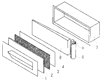
Fig. 1 is a schematic view showing an example of working
embodiment of an internally illuminated sign according to the present
invention. The information display section having a surface which is
retroreflective to the light from the front surface of the sign and is
2o transmissive to the light from the interior of the sign, is composed of
an information display layer (1), surface-protective layer (2),
retroreflective layer (3) and a light-scattering layer (4). An
illuminator disposed on the back of the information display section is
composed of a light source (5) and a back reflection layer (6).
Fur thermore, these information display device (1 - 4) and illuminator
(5, 6) are enclosed and held in a housing ('7).
In the working embodiment illustrated in Fig. l, the
information display layer (1) is installed in front of the
surface-protective layer (2) as an independent layer, but it can be
3o installed at any position such as at the fiont or back of any of those
surface-protective layer (2), retroreflective layer (3) and
light-scattering layer (4). Said information display layer (1) may be
installed in the form of a plastic or metal plate as an independent
layer, or it may be stuck on each of the layers (2 - 4) as a printed layer
or a colored plastic adhesive sheet layer.
CA 02491668 2005-O1-04
I~
In the embodiment of Fig. l, the back reflection plate has a
parabolic cross-section having a focus at the center position of the
light sour ce, and is so positioned as to enable the light emitted from
the light source to enter from the back of the prismatic retroreflective
elements at an entrance angle of 0 to 30° to the normal line of the
surfaces) constituting the infor mation display section.
Fig. 2 is a schematic view showing an example of working
embodiment of an internally illuminated sign according to the present
invention. The illuminator installed on the back of the information
display section is composed of a light source (5), light-guiding plate (8)
and a back reflection layer (6). Light emitted by the light source (5)
enters, either directly or as reflected by the back reflection layer (6),
into the light-guiding plate (8), and further its direction is changed to
direct the information display section. Such an embodiment using
an illuminator equipped with a lig~ht-guiding plate gives an internal
illuminator of uniform luminance.
Ii,ig. 3 is a schematic view showing still another embodiment of
an internally illuminated sign according to the present invention. In
the embodiment of Fig. 3, a planar luminophor (9) such as an EL or
'?0 LED array is adopted as the illuminator, and such an embodiment of
an illuminator equipped with a planar luminophor can also provide an
internal illuminator of uniform luminance. The power supply (10)
may be one which supplies power from an outside source to the planar
luminophor (9) ox' a storage battery which stores externally supplied
'?5 power from a solar battery or the like. Such power supply devices
can be adoped also in the embodiments of Fig. 1 or Fig. 2.
Fig. 4 shows a plan view (hig. 4 (A)) of a triangular-pyramidal
cube-corner retroreflective element which is an embodiment of
prismatic retroreflective element based on the principle of total
3o internal reflection useful for the present invention and a
cross-sectional view (Fig. 4(B)) thereof cut along the section line X - X'.
Such triangular-pyramidal cube-corner retroreflective elements are
normally configured as laterally symmetrical pairs of elements.
Preferably the optical axes of two elements in a pair have a same
35 degree of tilt in opposite directions, to favorably improve entrance
CA 02491668 2005-O1-04
angularity. The three faces constituting each element in a pair (a, b,
c or a', b', c') are substantially perpendicular to each other, which can
be given a minor deviation for improving visibility to a viewer who
observes the r etroreflection. As such a deviation, normally 0.001° to
5 0.1° is preferred.
Fig. 5 shows a plan view (Fig. 5 (A)) of a full cube type
cube-corner retroreflective element which is another embodiment of
prismatic retroreflective element based on the principle of total
internal reflection useful for the present invention and a
to cross-sectional view (Fig. 5(B)) thereof cut along the section line X - X'.
The three faces (a, b, c) constituting each element are substantially
perpendicular to each other, which can be given a minor deviation for
improving visibility to a viewer who observes the retroreflection. As
such a deviation, normally 0.001° to 0.1° is preferred.
15 Fig. 6 shows a plan view (Fig. 6(A)) of a tent-type cube-corner
retroreflective element which is another embodiment of prismatic
retroreflective element based on the principle of total internal
reflection useful for the present invention and a cross-sectional view
(Fig. 6(B)) thereof cut along the section line X - X'. Similar to the
20 elements as illustrated in Figs. 4 and 5, the three faces (a, b, c)
constituting each element are substantially perpendicular to each
other, which can be given a minor deviation for improving visibility to
a viewer who observes the retroreflection. As such a deviation,
normally 0.001° to 0.1° is preferred.
Fig. 7 shows a plan view (Fig.7(A)) of another full cube type
cube-corner retror eflective element which is an embodiment of
prismatic retroreflective element based on the principle of total
inter nal reflection useful for the present invention and a
cross-sectional view (Fig. 7(B)) thereof cut along the section line X - X'.
3o Of the four faces (a, b, c, and d) constituting the element, each pair of
confr outing surfaces (a and b, c and d) are substantially perpendicular
to each other, which can be given a minor deviation for improving
visibility to a viewer who observes the retroreflection. As such a
deviation, normally 0.001° to 0.1° is preferred.
Fig. 8 is a cross-sectional view of a prismatic retroreflective
CA 02491668 2005-O1-04
~1
sheeting according to prior art, in which an air layer (17) is
encapsulated by bonded areas (18). This retroreflective sheeting is
formed of a surface-protective layer (11), prismatic retroreflective
layer (12), binder layer (13), support layer (14), adhesive layer (15)
and a release layer (16). Said release layer (16) is peeled off when
the sheeting is stuck on other supporting member.
Fig. 9 is a cross-sectional view of a prismatic retroreflective
sheeting according to the present invention which is not encapsulated
and is free of any bonded area. This retroreflective sheeting is
1o composed of a release layer (16), adhesive layer (15),
surface-protective layer (11) and a prismatic retroreflective layer (12).
Said release layer (16) is peeled off when the sheeting is stuck onto
other supporting number. Underneath the prismatic retroreflective
layer (12), an air layer is necessary. Also as an information display
15 layer, a color ed transparent or opaque printed layer may be provided
on or under the adhesive layer (15) or a surface-protective layer.
Said prismatic retroreflective layer (12) is constructed from prismatic
retroreflective elements following the principle of total internal
reflection, and hence the prismatic retroreflective layer (12), as shown
2o in Fig.9 has no metallic coating or that sort on its bottom plane and is
transparent. In consequence, the retroreflective sheeting Fig.9 is
retroreflective of the light coming from above and is transmissive to
the light coming from the underside. That is, the retroreflective
sheeting of Fig. 9 transmits the light from the light source provided
below Fig. 9, and also transmits the light from the illuminator
disposed inside the sign.
Fig. 10 shows a plan view of a corner-cube retroreflective
element having three pairs of optical axes, which is an embodiment of
the prismatic retroreflective elements according to the principle of
so total internal reflection, as disclosed in Japanese Patent Application
2001-241964.
Fig. 11 shows the cross-section of the corner-cube
retroreflective element as shown in Fig. 10. The corner-cube
retroreflective element as illustrated in Figs. 10 and 11 comprises
35 three pairs of corner-cube elements (H11, H12, H13 and H21, H22 and
CA 02491668 2005-O1-04
H23), and the three pairs of the optical axes of the respective pairs
(tll, t12, t13 and t21, t22, t23) have the same tilt angle (8) and
opposite directions of the tilt.
Fig. 12 is a schematic view showing an example of working
embodiment of an internally illuminated sign according to the present
invention. The information display section having a surface which is
retroreflective to the light coming from the front of the sign and is
transmissive to the light from interior of the sign is formed of a
surface protective layer (2) and a retroreflective layer (3). The
1o illuminator installed at the internal space of said information display
section is constituted of a light source (5). Furthermore, these
information display device (2, 3) and the light sour ce (5) are enclosed
and held in a housing (7) which is separated into a top part and a
bottom part, and are self-sustainable. An information display layer
(1) or a light-scattering layer (4) may further be installed on the
surface or back of the retroreflective layer (3) of the internally
illuminated sign of Fig. 12.
An effect of the present invention is: because, in the internally
illuminated sign according to the present invention , which is useful
2o as traffic signs such as road signs, regulatory signs, guide signs,
construction signs and the like, and commercial signs and has an
information display section having a surface retroreflecting light
coming from front of the signs and transmitting light coming from
interior of the signs, whereby exhibiting improved visibility not only
in daytime but also at night, a retroreflective element-assembled
plane formed by a dense assembly of a large number of the elements
provides a continuous retroreflective plane, and at least at the
retroreflective area of the information display section the prismatic
back surface has no bonded area with other layers) and is
3o substantially free of encapsulation structure, the internally
illuminated sign exhibits excellent retroreflectivity and excellent
transmission of light from interior.
Another effect of the invention is that the internally
illuminated signs exhibit excellent visibility at broad angles, in
particular, even in such occasions as power failure or lamp troubles,
CA 02491668 2005-O1-04
23
because they adopt retroreflective elements having excellent
retroreflection character istics at broad entrance angles.
Still further effect of the present invention is that the
retroreflective, internally illuminated signs exhibit more improved
visibility not only in daytime but also at night, because the daylight of
the information display sections used therein is fluorescent light.