Note: Descriptions are shown in the official language in which they were submitted.
CA 02491730 2005-01-04
WO 2004/004791 PCT/SE2003/001169
1
METHOD AND DEVICE AT A DAIRY FARM
TECHNICAL FIELD OF THE INVENTION
The present invention relates to dairy farming, and to
disinfection and sterilization related thereto.
DESCRIPTION OF RELATED ART AND BACKGROUND OF THE INVENTION
When a milking animal, such as a cow, presents herself for
milking it is important to ensure that the teat cups to be
attached to the teats of the milking animal are clean and free
of any condition that could contaminate the teats of the milking
animal. Therefore, it is customary to clean the teat cups
between milkings of milking animals, where either a cleaning
liquid or pure water is used.
It is also customary, for the same reason, to clean the teats of
each milking animal prior to the attachment of the teat cups.
For teat cleaning, dedicated teat cleaning cups or brushes may
be employed.
However, while such cleaning removes dirt from the teats and
provides for an overall hygienic environment, there is
nevertheless a risk of communicating infections, such as for
instance mastitis, from one animal to another.
In Research Disclosure,. April 2000, publication No. 444037, p.
530, it is proposed to spray the surfaces of the teat cups and
the teat cleaning cups that potentially are exposed to the
animals with hot steam to heat up the surfaces to a temperature,
at which bacteria are killed. It is also proposed to illuminate
the surfaces with UV light.
CA 02491730 2005-01-04
WO 2004/004791 PCT/SE2003/001169
2
In US 6,267,077 is described to employ a rinsing liquid with an
additive, such as sodium hypochlorite, via supply lines and
spray nozzles to clean and disinfect components of a milking
machine, such as a cleaning member and a robot arm.
In US 6,276,297 is disclosed a disinfecting device that
disinfects those parts of a milking equipment and of a cleaning
device which contact the teats and also usually the udder of an
animal to be milked. The disinfecting device comprises an
ultraviolet light source for destroying harmful bacteria by
means of exposing them to UV radiation.
SUIU4ARY OF THE INVENTION
The known disinfecting techniques are all energy and time
consuming being used at an automatic milking machine to ensure
that no infections are transmitted from animal to animal. The
high energy needed results in an inefficient disinfection or
sterilization process, and the time delays introduced by the
process result in an inefficient utilization of the milking
machine, and as an automatic milking machine involves heavy
expenditure and has a limited milk production capacity, such
time delays may not be acceptable.
Further, an infection may be transmitted from animal to animal
at other places in a dairy farm. For instance, when milking
animals are lying down in a resting stall small amounts of milk
may leak, and as a consequence there is a risk of infection via
the resting stalls. Besides, the inventors believe that surfaces
of a feeding stall, which an animal may come into contact with,
e.g. a feeding device such as a feeding manger, may be a source
for transmission of infections.
CA 02491730 2005-01-04
WO 2004/004791 PCT/SE2003/001169
3
Accordingly, it is an object of the present invention to provide
a method and a device, respectively for automatically
disinfecting or sterilizing in an automated milking system,
which overcome the above-identified problems associated with
prior art.
It is in this respect a particular object of the invention to
provide such a method and such a device that are effective,
accurate, reliable, safe, and of low cost.
It is a further object of the invention to provide such a method
and such a device that are easily implemented into existing
dairy farm equipment.
These objects among others are attained by methods and devices
as claimed in the appended patent claims.
By means of retrieving information regarding the health of each
milking animal entering any of a resting, a milking, or a
feeding station, and automatically disinfecting or sterilizing
at least a portion of the station if the information as
retrieved reveals that a milking animal entering the station has
a transmittable infection, wherein the disinfection or the
sterilization is performed after that the infectious animal has
left the station, it can be safeguarded that no infections are
transmitted via the station while the disinfection or the
sterilization only has to be performed after a visit by an
infectious animal. The at least portion of the station includes
preferably surfaces that an infectious animal may come into
contact with. Assuming that a large number of milking animals
are healthy, the disinfection or the sterilization has only to
be performed occasionally, and hence energy consumption is
reduced and time is saved.
CA 02491730 2005-01-04
WO 2004/004791 PCT/SE2003/001169
4
Preferably, a computer holding a database with information of
the milking animals and their health is provided, wherein
information regarding the health of each milking animal entering
the station is retrieved by means of referring to the database.
The information may be entered into the database manually, or
may be entered automatically from a computer-connected measuring
device for measuring a health-related parameter of the milking
animals.
Still preferably, the station may be automatically disinfected
or sterilized irrespective of the information retrieved if a
particular time, e.g. a day or a week, has lapsed since last
disinfection or sterilization of that station. This is to ensure
that the milking station is disinfected or sterilized e.g. at
least once a day or once a week even if all animals visiting the
station are healthy in order to ensure a good hygiene in the
station.
Yet preferably, the station may be automatically disinfected or
sterilized irrespective of the information retrieved if (i) it
is established that no milking animal visits or is to visit the
station in the near future, and (ii) a particular time has
lapsed since last disinfection or sterilization of that station
or at least a portion thereof was performed. Such approach is
advantageous since it does not reduce the utilization of the
station. The second condition is there to prevent the station
from being repeatedly disinfected or sterilized if the station
is not visited by any milking animal for a longer time.
Still preferably, the station may be automatically disinfected
or sterilized irrespective of the information retrieved, e.g.
more often, if there is an infectious disease spread among the
milking animals that have access to the station.
CA 02491730 2005-01-04
WO 2004/004791 PCT/SE2003/001169
Yet preferably, each station that is provided with an animal
identification device (including resting, feeding and milking
stations) located in an area housing a herd of milking animals
may be subjected to the disinfection or the sterilization.
5 Consequently, all surfaces of the equipment an infectious animal
in the area may contact for a specified purpose or accidentally
shall be automatically disinfected or sterilized after the
animal has been identified at, and subsequently left, that
station.
Further characteristics of the invention, and advantages
thereof, will be evident from the detailed description of
embodiments of the present invention given hereinafter and the
accompanying Figs. 1-4, which are given by way of illustration
only, and thus are not limitative of the present invention.
In the following detailed description the milk producing animals
are cows. However, the invention is not limited to cows, but is
applicable to any animals having the capability to produce milk,
such as sheep, goats, buffaloes, horses, etc.
BRIEF DESCRIPTION OF THE DRAWINGS
Fig. 1 illustrates, schematically, an arrangement for housing a
herd of cows, wherein embodiments of the present invention are
implemented.
Fig. 2 illustrates, schematically, in a perspective view
portions of an automated milking station as being comprised in
the arrangement of Fig. 1.
Fig. 3 illustrates, schematically, in a flow diagram a method
according to a particular embodiment of the present invention.
CA 02491730 2005-01-04
WO 2004/004791 PCT/SE2003/001169
6
Fig. 4 displays schematically an example of an extract of a
database comprised in a processing device of the animal
arrangement of Fig. 1.
Fig 5 illustrates, schematically, a feeding station wherein a
further embodiment of the present invention is implemented.
Fig 6 illustrates, schematically, a resting station wherein
still a further embodiment of the present invention is
implemented.
DETAILED DESCRIPTION OF EMBODIMENTS
Fig 1. illustrates an animal arrangement for housing a herd of
freely walking cows, which comprises an area 1 defined by
enclosure means 2 in the shape of a fence, a grid or the like.
In the area 1, there is provided a milking station 3 arranged
for voluntary milking of the freely walking cows, i.e. the cows
enter the milking station 3 in order to be milked when they want
to. The milking station 3 comprises an enclosure having an inlet
gate 4 and an outlet gate 5, which are both capable of being
opened automatically.
The milking station 3 comprises further an automatic milking
machine 10 including teat cups 11 connected to an end unit 12 by
means of milk lines 13. The milking machine 10 includes a robot
or automatic handling device 14 having an arm 15 provided with a
gripper. The handling device 14 is arranged to automatically
apply the teat cups 11 of the milking machine 10 to the teats of
a cow present in the milking station 3 prior to milking.
In Fig. 2 portions of the milking station 3 are schematically
illustrated in a perspective view. Three of the teat cups 11 are
arranged in a teat cup rack or magazine 16, whereas the fourth
one is held by the gripper of the arm 15.
CA 02491730 2005-01-04
WO 2004/004791 PCT/SE2003/001169
7
Further, the milking station 3 may comprise a feeding device or
manger 17 provided in the front end of the milking station 3,
the purposes of which being to entice the cow to enter the
milking station 3 for milking.
Still further, the milking station 3 comprises an identification
member 18 provided to identify a cow approaching the milking
station 3, and a central processing and control device 19, which
is responsible for central processing and controlling of the
animal arrangement, which inter alia includes the initiation of
various activities in connection with the milking such as e.g.
opening and closing of the gates 4 and 5, and control of the
milking machine 10 and its handling device 14.
The central processing and control device 19 comprises typically
a microcomputer, suitable software, and a database. An example
of an extract of the database is illustrated in Fig. 4, wherein
figures are given in arbitrary units. The database includes
typically information of each of the cows in the area 1, such as
e.g. when the respective cow was milked last time, when she was
fed last time, her milk production, her health, etc.
Particularly, the database may store information such as whether
the respective cow has mastitis or any other infection, which of
her teats being infected, etc. To this end, the sixth column of
the database indicates whether a cow is healthy (1), has
mastitis (2), or has another infection (3).
A cow approaching the milking station is thus identified by the
identification member 18, and the central processing and control
device 19 may then, depending on the identification, give the
cow access to the milking station 3 by means of opening the
inlet gate 4. The teats may be cleaned by a teat cleaning device
such as a teat cleaning cup or brushes (not explicitly
illustrated in Fig. 1, but shown as 21 and 22 in Fig. 2),
CA 02491730 2005-01-04
WO 2004/004791 PCT/SE2003/001169
8
whereafter the teat cups 19 are applied to the teats of the cow
in the milking station 3.
During milking, milk is drawn from the teats of the cow by means
of vacuum being applied to the teat cups 11. The milk drawn is
collected in the end unit 12. After the milking has been
completed the outlet gate 5 is opened and the cow may leave the
milking station 3.
Each teat cup may be connected individually by means of the
respective milk line 13 to the end unit 12, from which the milk
is pumped to a cooled storage tank (not illustrated).
It shall be appreciated by the man skilled in the art that there
may be provided one or several milking stations of the above-
described kind in the area 1 of Fig. 1.
Furthermore, the area 1 may house one or several feeding stalls
or stations 24, each being provided with a cow identification
member 25 provided to identify a cow entering the respective
feeding station 24 for eating and drinking. Each identification
member 25 is connected individually to the central processing
and control device 19 such that central processing and control
device 19 at each instant can establish whether each feeding
station 24 is being visited and by which cow.
Correspondingly, the area 1 may house one or several resting
stalls or stations 26, each being provided with a cow
identification member 27 provided to identify a cow entering the
respective resting station 26 for resting. Each identification
member 27 is connected individually to the central processing
and control device 19 such that the central processing and
control device 19 at each instant can establish whether each
resting station 26 is occupied and by which cow.
CA 02491730 2005-01-04
WO 2004/004791 PCT/SE2003/001169
9
The provisions described above provide for an effective and
hygienic highly automated dairy farming facility with high milk
production. Nevertheless, recent investigations may suggest that
the cleaning performed is not effective regarding the spreading
of microorganisms and bacteria, which may transfer infectious
illnesses or infections from cow to cow in the area 1.
The milking station 3 of the animal arrangement of Fig. 1 is
therefore provided with an apparatus 29 for disinfection and/or
sterilization of various parts of the milking station 3 that a
cow may contact for a specified purpose or accidentally, e.g.
surfaces of the teat cups 11, the teat cleaning devices 21, 22,
the manger 17, a front portion of the arm 15 of the handling
device 14, the gates 4, 5, the walls and floor of the milking
station 3.
Correspondingly, each feeding station 24 and each resting
station 26 is provided with a respective apparatus 30, 31 for
disinfection and/or sterilization of various parts of that
station. Parts to be disinfected and/or sterilized may be inner
walls, and the floor of the station and in case of a feeding
station the manger/feeding device thereof may need to be
disinfected and/or sterilized.
Each apparatus 29, 30, 31 for disinfection and/or sterilization
is connected individually to the central processing and control
device 19, which is responsible for the operation of the
respective apparatus. Alternatively, each apparatus 29, 30, 31
is provided with a respective microprocessor for control of its
operation, which microprocessor in turn is connected to the
central processing and control device 19 for receiving commands
from there.
CA 02491730 2005-01-04
WO 2004/004791 PCT/SE2003/001169
Further, each apparatus 29, 30, 31 for disinfection and/or
sterilization may use any of heat treatment, radiation or
treatment with chemicals to render pathogenic microorganisms
harmless or remove them. By disinfection is here meant rendering
5 microorganisms such as bacteria, virus and pathogenic
microscopic fungi harmless or remove them to such an extent that
the treated objects or surfaces do not transmit infections,
whether there is put a higher requirement on sterilization to
render all microbes harmless.
10 In Fig. 2 is illustrated three different apparatuses 32, 33, 34
for disinfection and sterilization that may be used, by
themselves or in any combination, as any of the apparatuses 29,
30, 31 as illustrated in Fig. 1.
The disinfection and/or sterilization apparatus 32 is based on
heat treatment and includes an injector 35 connected to a hot
fluid generator 36 via a supply tube 37. The injector 35
includes a nozzle 38, which preferably is adjustable. The hot
fluid generator 36 may be adapted for generation of steam or hot
air, which, during use, is flown through the tube 37 and out
through the nozzle 38 as a jet towards an object, or part
thereof, to be disinfected or sterilized.
The disinfection and/or sterilization apparatus 33 is based on
use of chemicals or disinfectants such as an alcohol and
includes an injector 39 connected to a supply unit 40 via a
supply tube 41. The injector 39 includes a nozzle 42, which
preferably is adjustable. The supply unit 40 is filled with a
chemical or disinfectant, which, during use, is flown through
the tube 41 and out through the nozzle 42 as a jet towards an
object, or part thereof, to be disinfected or sterilized.
CA 02491730 2005-01-04
WO 2004/004791 PCT/SE2003/001169
11
Finally, the disinfection and/or sterilization apparatus 34 is
based on use of radiation for the disinfection or the
sterilization and includes a radiation device 43, such as a UV
laser source or an X-ray tube, connected to a power supply unit
44 via a cable 45. In front of the radiation device 43 there is
arranged a collimator 46 or similar, which preferably is
adjustable. During use, power is supplied to the radiation
device 43 via the cable 45 and as a result the radiation device
43 generates UV light or X-rays, which via the collimator 46 is
output from the radiation device 43 as a beam of radiation,
which in turn is directed towards an object, or part thereof,
to be disinfected or sterilized.
Any of the disinfection and/or sterilization apparatuses 32,
33, 34 may be handled by the handling device 14, or by other
equipment (not illustrated) in order to position and direct the
apparatuses 32, 33, 34 appropriately to reach objects /surfaces
to be disinfected or sterilized.
Figs. 5 and 6 illustrate schematically a feeding station and a
resting station, respectively, in each of which a respective
particular embodiment of the present invention is implemented.
The feeding station 24 of Fig. 5 includes a feeding device or
manger 71 and a stationary disinfection/sterilization device 73
having four different supply lines, each of which ends in a
nozzle 74 mounted in the wall of the feeding station 24. The
nozzles 74 are oriented to direct any disinfection/
sterilization agent as supplied by the disinfection/
sterilization device 73 towards the manger 71 to effectively
disinfect/sterilize it. In other respects the disinfection/
sterilization device 73 may be connected and operated as any of
the disinfection and/or sterilization apparatuses described
above.
CA 02491730 2010-05-11
12
The resting station 26 of Fig. 6 includes a mat 75 to provide a
softer and more comfortable bed for the resting cow. Further, a
stationary disinfection/sterilization device 76 having six
different supply lines is provided, where each of the supply
lines ends in a nozzle 77 mounted in the wall of the resting
station 26. The nozzles 77 are oriented to direct any
disinfection/sterilization agent as supplied by the
disinfection/sterilization device 76 towards the mat 75 to
effectively disinfect/sterilize it. In other respects the
disinfection/sterilization device 76 may be connected and
operated as any of the disinfection and/or sterilization
apparatuses described above.
It shall be appreciated to the man skilled in the art that the
disinfection and/or sterilization apparatuses described above
are merely examples, and that virtually any kind of apparatus
having the capability of disinfection or sterilization may be
used in the present invention. In this regard reference is made
to the technical field of disinfection and sterilization, and
particularly to the documents referred to in the prior art
section, i.e. Research Disclosure publication No. 444037, US
6,267,077, and US 6,276,297, as well as to our co-pending
Swedish patent application No., 0200802-7, entitled Method and
arrangement at a dairy farm, and filed on March 22, 2002.
Since disinfection and sterilization is energy and time
consuming, and moreover large surfaces/objects have to be
disinfected or sterilized in order to ensure that transmission
of infectious illnesses and infections is impeded. To this end,
the present inventors proposes to disinfect or sterilize
equipment and surfaces that a cow has contacted or may have
CA 02491730 2005-01-04
WO 2004/004791 PCT/SE2003/001169
13
accidentally contacted only if some important conditions are
met.
According to the present invention the processing and control
device 19 is adapted to retrieve information regarding the
health of each of the cows entering each station 3, 24, 26, and,
provided that the information retrieved reveals that a cow
entering any of the stations 3, 24, 26 has an infection that is
capable of being transmitted to other cows, to control the
respective disinfecting and/or sterilizing apparatus 29, 30, 31
to automatically disinfect or sterilize equipment/ surfaces of
that station 3, 24, 26, which the infectious cow may possibly
have contacted, after that the cow has left the station 3, 24,
26.
Preferably, in order to ensure that no infection is transmitted
from cow to cow each station located in the area 1 shall be
provided with an animal identification device; and all surfaces
of that station, which a cow in the area 1 may contact for a
specified purpose or accidentally, shall be disinfected or
sterilized after a visit by an infectious cow.
Still preferably, means are provided to ensure that no further
cows are admitted to enter the station 3, 24, 26 until the
disinfection or the sterilization has been terminated. In the
milking station 3 this is ensured by having the inlet gate 4
closed. Similar inlet gates may be provided at each feeding 24
and resting 26 station.
The information regarding the health of each of the cows
entering each station 3, 24, 26, which the processing and
control device 19 is adapted to retrieve, may be information
held in the database such as whether the respective cow has
mastitis or any other infection, which of her teats being
CA 02491730 2005-01-04
WO 2004/004791 PCT/SE2003/001169
14
infected, etc. The information may have been entered into the
database manually e.g. by the farmer, or it may have been
communicated automatically to the central processing and control
device 19, wherafter the central processing and control device
19 updates the database.
For instance, the central processing and control device 19 may
be electronically connected to e.g. a laboratory, to which milk
samples are sent, which laboratory may regularly communicate the
results of the samples analysis back to the dairy farm (i.e. to
the central processing and control device 19).
Alternatively, the processing and control device is connected to
a measuring device for measuring a health-related parameter of
the cows, and the processing and control device 19 is adapted to
retrieve the health-related parameters and use them as the
information regarding the health of each of the cows entering
each station.
In Fig. 1 is illustrated an on-site measurement or analysis
equipment 47 for measuring such a health-related parameter. The
measurement equipment 47 may e.g. be a conductance-measuring
device and/or an infrared spectrometer device for measuring the
milk produced by each cow milked in the milking station 3. The
measurement equipment may alternatively be comprised of any kind
of on-site or on-line arrangement for automatic or semi-
automatic milk analysis. By means of such milk analysis, for
instance, the content of bacteria and spores, the content of
sodium and potassium, the lactose concentration, and the somatic
cell count value can be obtained. The measurement equipment 47
can be arranged to measure milk in the end unit 12, in the milk
lines 13, or in the teat cups 11.
CA 02491730 2005-01-04
WO 2004/004791 PCT/SE2003/001169
Alternatively, the on-site measurement equipment 47 may be an
activity meter for measuring the activity of the cow (where an
extraordinary high or low activity may indicate that the cow
does not feel alright).
5 Other health-related parameters that may be measured,
particularly automatically, at any of a milking station, a
resting station or a feeding station include e.g. the milk
amount produced by the cow, the feed consumption by the cow, the
temperature of the cow and the weight of the cow.
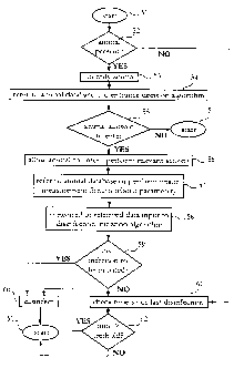
10 With reference next to Fig. 3, which is a flow diagram of an
algorithm for automatically disinfecting or sterilizing, which
may be implemented in the central processing and control device
11 of the animal arrangement of Fig. 1, a particular embodiment
of the present invention will be described. The algorithm will
15 be exemplified as being implemented in the milking station 3,
but may, mutatis mutandis, be implemented into any of the other
stations of Fig. 1, or in fact in any other milking, feeding or
resting station known in the art.
In a step 51, the algorithm is initiated, and in a step 52 it
is checked whether a cow is present in front of the milking
station 3. If the answer is negative the algorithm is continued
with a step 61 to be described further below, and if the answer
is affirmative, the cow is, in a step 53, identified.
Subsequently, a decision algorithm is, in a step 54, run to
decide whether the cow identified shall be allowed to enter the
milking station 3, where the decision algorithm may retrieve
data from the database of Fig. 4. Then, it is, in a step 55,
checked whether the cow is allowed to enter the station, and if
the answer is negative the algorithm is returned to the initial
CA 02491730 2005-01-04
WO 2004/004791 PCT/SE2003/001169
16
step 51. If the answer is affirmative the inlet gate 4 is, in a
step 56, opened and the cow is allowed to enter to be milked.
While the cow is prepared for milking and subsequently milked,
the Fig. 3 algorithm refers, in a step 57, to the database
and/or performs an on-site measurement of a health related
parameter to retrieve data regarding the health of the cow,
whereafter the data is, in a step 58, input into a disinfection
initiation algorithm for deciding whether the data reveals that
the cow has an infection, e.g. mastitis, that is capable of
being transmitted to other cows.
Next, in a step 59 it is decided whether disinfection or
sterilization shall be initiated and if so it is in a step 60
initiated, wherafter the algorithm is returned to the initial
step 51. Note that step 60 shall not be performed until it has
been assured that the cow has left the station. If disinfection
or sterilization shall not be initiated it is, in a step 61,
checked how long time has lapsed since disinfection or
sterilization was last performed. This step is also performed
directly after step 52 if there is no cow to visit the station
3.
The time lapsed is, in a step 62, compared with a threshold
value and if the time lapsed is higher than the threshold value
the algorithm is passed to the step 60 and initiates
disinfection or sterilization, wherafter the algorithm is
returned to the initial step 51. If the time lapsed is not
higher than the threshold value, the algorithm is directly
returned to the initial step 51.
Note that a lower threshold may be used if no cow is present in
front of the milking station 3 since disinfection or
CA 02491730 2005-01-04
WO 2004/004791 PCT/SE2003/001169
17
sterilization in this instance does not affect the utilization
of the milking station.
Further, the threshold value may be set depending on the
percentage of the cows in the area 1 that have an infection
capable of being transmitted to other milking animals, where the
percentage is deduced from information retrieved from the
database regarding the health of each of the cows in the area 1.
By this provision it can be ensured that the station is
disinfected or sterilized more often if there are a high number
of infectious cows in the stock.
It will be obvious that the invention may be varied in a
plurality of ways. Such variations are not to be regarded as a
departure from the scope of the invention. All such
modifications as would be obvious to one skilled in the art are
intended to be included within the scope of the appended
claims.