Note: Descriptions are shown in the official language in which they were submitted.
CA 02492329 2005-01-11
1
Title of the invention
Method and device for high-temperature heat treatment
and densification by chemical infiltration of carbon
texture in a steam phase
Background of the invention
The invention relates to obtaining parts made of
composite material comprising a carbon reinforcing fabric
densified by a matrix formed by chemical vapor
infiltration (CVI).
A particular field of application for the invention
is that of obtaining parts made of thermostructural
composite material comprising carbon fiber reinforcement
densified by a matrix of carbon or ceramic. Such parts
are used in the fields of aviation and space, and also
for friction elements, in particular for brake disks.
The reinforcing fabric is typically obtained using
carbon precursor fibers such as preoxidized
polyacrylonitrile (PAN) fibers, pitch fibers, phenol
fibers, or rayon fibers, all of which withstand the
textile operations needed to shape such fabrics better
than do carbon fibers.
The carbon precursor fiber fabric is transformed
into a carbon fiber fabric or preform by applying heat
treatment. On an industrial scale, the heat treatment is
performed in an oven at substantially atmospheric
pressure while being swept with an inert gas such as
nitrogen. Temperature is raised progressively up to
about 900 C. The transformation of the precursor into
carbon is almost total, with the resulting carbon content
generally exceeding 95%, and possibly reaching 99% or
more. The loss of mass is considerable, being about 50%,
and is accompanied by a large volume of gaseous effluent
being produced.
For at least some applications, it is necessary not
only to transform the precursor into carbon, but also to
perform subsequent heat treatment at high temperature, in
CA 02492329 2005-01-11
2
particular in order to eliminate metals or metallic
impurities coming from the precursor and/or in order to
confer special properties on the carbon fibers. This
applies in particular to eliminating the sodium contained
in preoxidized PAN, which sodium can have a harmful
effect on the ability of the resulting composite material
parts to withstand oxidation.
That is why, following a first carbonizing step and
prior to densifying the fabric, preoxidized PAN carbon
precursor fiber fabrics are sometimes subjected to heat
treatment at high temperature and under reduced pressure
in order to eliminate sodium by sublimation. This second
step is performed under low pressure while sweeping with
an inert gas such as nitrogen, and at a temperature that
is generally higher than 1000 C, typically lying
approximately in the range 1400 C to 1650 C in order to
eliminate sodium, and possibly reaching 2000 C or 2200 C
or even 2500 C in order to eliminate other metallic
impurities and/or to transform the properties of the
fibers.
Steps of carbonizing, performing heat treatment at
high temperature, and subsequent densification by
chemical vapor infiltration are conventionally performed
in respective special purpose installations. In
industrial use, each of these steps lasts for several
days. This explains why, in particular, the process of
obtaining sodium-free composite material parts containing
fiber reinforcement made using preoxidized PAN precursor
is lengthy and expensive.
The same problems arise with carbon fibers coming
from precursors other than preoxidized PAN and likewise
containing sodium or other metals for elimination, such
as magnesium or calcium, and also whenever it is
necessary to eliminate metals or metallic impurities such
as iron, nickel, or chromium, for example, which require
heat treatment at high temperature, typically up to not
CA 02492329 2010-06-16
3
less than 2000 C or 2200 C, or even 2500 C in order to be
eliminated by sublimation.
Summary of the invention
The present invention is directed towards the
provision of a method and an installation enabling
composite material parts to be obtained by densifying
carbon fiber preforms by means of chemical vapor
infiltration, in particular preforms containing one or
more metals that need to be eliminated, while achieving
very significant savings in cost and in treatment
duration.
In accordance with one aspect of the present
invention, there is provided a method of subjecting
carbon fiber performs to high temperature heat treatment
and densification comprising the steps of:
= placing the carbon fiber preforms in an enclosure;
= subjecting the preforms in the enclosure to heat
treatment while sweeping the enclosure with inert gas
under low pressure, the heat treatment being carried out
at a temperature higher than 1000 C to eliminate metallic
impurities in the fibers;
= during the heat treatment, continuously extracting
gaseous effluent containing metallic impurities through a
first effluent outlet connected to a first effluent
exhaust circuit;
= at the end of heat treatment, closing the first
gas effluent outlet so as to isolate the effluent exhaust
circuit from the enclosure;
= interrupting sweeping of the enclosure with inert
gas; and
= leaving the heat-treated preforms in the enclosure
and subjecting them to densification by admitting a
reagent gas into the enclosure through at least one
reagent gas admission duct opening out into the
enclosure, gaseous effluent being extracted through a
second effluent
CA 02492329 2010-06-16
3a
outlet distinct from the first, said second outlet being
closed during the heat treatment step.
In a particular implementation, the method includes
neutralizing the metal contained in the gaseous effluent
extracted from the enclosure during the heat treatment
step.
CA 02492329 2005-01-11
4
The metal, typically sodium, may be neutralized
after the end of the heat treatment, e.g. by hydrating
the sodium that has condensed on the wall of a pipe
connected to the first effluent outlet. This may be
achieved by injecting water into said pipe, in particular
by injecting steam, possibly diluted in an inert gas such
as nitrogen or argon.
In a variant, the metal, typically sodium, may be
neutralized continuously during the heat treatment by
injecting a neutralizing agent into the gaseous effluent
while it is being extracted. The sodium-neutralizing
agent may be water in the form of steam, or it may be
carbon dioxide, optionally diluted in an inert gas such
as nitrogen or argon.
In another particular implementation of the method,
the first effluent evacuation circuit is purged after the
end of the heat treatment. This purging may be performed
during the step of densifying the carbon fabric, with the
first effluent exhaust circuit then being isolated from
the enclosure. Purging may be performed by injecting
cleaning water into the first exhaust circuit, or by
disassembling said circuit at least in part and washing
it.
Advantageously, the or each duct for admitting
reagent gas into the enclosure is swept by an inert gas
during the heat treatment step so as to prevent any
portion of the gaseous effluent produced during heat
treatment gaining access to said duct.
In yet another particular implementation of the
method, the first effluent exhaust circuit can be used,
at least in part, to inject a cooling gas into the
enclosure to cool the composite material parts as
obtained after the end of the densification step.
Another object of the present invention is to
provide an installation enabling the above-described
method to be implemented.
CA 02492329 2005-01-11
This object is achieved by an installation
comprising an enclosure, means for heating the enclosure,
at least one inlet for admitting an inert sweeping gas
into the enclosure, a first outlet for exhausting gaseous
5 effluent from the enclosure, and a first effluent exhaust
circuit comprising an effluent exhaust pipe connected to
the first gaseous effluent outlet, in which installation
there are further provided, according to the invention,
at least one reagent gas admission duct opening out into
the enclosure, a second outlet for exhausting gaseous
effluent from the enclosure, a second effluent exhaust
circuit connected to the second gaseous effluent outlet,
a valve for isolating the first effluent exhaust circuit
from the enclosure, and a valve for isolating the second
effluent exhaust circuit from the enclosure.
In a particular embodiment, the installation
comprises an injector device for injecting an agent into
the effluent exhaust pipe connected to the first gaseous
effluent outlet, said agent serving to neutralize metal
contained in effluent extracted by the first effluent
exhaust circuit. The injector device is disposed
downstream from the valve for isolating the first
effluent exhaust circuit. A plurality of injection
points may be provided that are spaced apart from one
another along the effluent evacuation pipe.
Means may be provided to enable the duct for
admitting the reagent phase to be swept with an inert
gas.
In another particular embodiment, the installation
includes an inlet for admitting cooling gas into the
enclosure. The cooling gas admission inlet and the first
gaseous effluent outlet may be constituted by a common
port.
Brief description of the drawings
The invention will be better understood on reading
the following description given by way of non-limiting
CA 02492329 2005-01-11
6
indication and with reference to the accompanying
drawings, in which:
= Figure 1 is a highly diagrammatic view partially
in section showing an embodiment of an installation of
the invention;
= Figure 2 is a more detailed view of the device for
injecting neutralizing agent into the Figure 1
installation; and
= Figure 3 is a flow chart showing the steps in an
implementation of the method of the invention.
Detailed description of embodiments
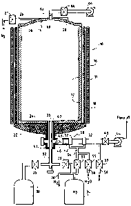
Figure 1 shows an installation comprising an oven 10
having a susceptor 12 in the form of a vertical-axis
cylinder defining the sides of a volume 11 into which
carbon fiber fabrics (not shown) are loaded, e.g. fiber
preforms or pieces of fabric obtained by carbonizing
fibers made of preoxidized PAN fibers. The susceptor 12
is surmounted by a cover 14.
The susceptor 12 is made of graphite for example and
it is heated by inductive coupling with an inductor 16
which surrounds the susceptor, with thermal insulation 18
being interposed between them. The inductor is powered
by a circuit (not shown) which delivers electricity as a
function of the heating requirements of the oven.
The bottom of the oven is constituted by a thermal
insulator 22 covered by an oven soleplate 24, e.g. made
of graphite, on which the susceptor stands.
The assembly is received inside a casing, e.g. made
of metal, (not shown).
A duct 26 for feeding inert gas for sweeping
purposes, e.g. nitrogen, is connected to a source of
nitrogen via a valve 27 and to one or more orifices 28
for injecting inert sweeping gas into the oven 10 through
the cover 14.
An inlet 30 for admitting reagent gas into the oven
is formed at the bottom thereof. The inlet 30 is
CA 02492329 2005-01-11
7
connected to a feed duct 32. It is connected firstly to
a source 34 of inert gas such as nitrogen (N2), and
secondly to a source 36 of reagent gas. Valves 33 and 35
enable the source 34 or the source 36 to be connected
selectively to the duct 32. The source 34 is connected
to the valve 27 mounted on the duct 26. The reagent gas
source can be constituted by a plurality of containers
containing different gases.
A first outlet 40 for extracting effluent gas from
the oven is also formed through the bottom thereof. In
the example shown, the outlet 40 is annular in shape,
surrounding the end of the duct 32 connected to the inlet
30. Naturally, the outlet 40 could be formed separately
from the inlet 30 in a different zone of the bottom of
the oven. It should also be observed that a plurality of
distinct reagent gas inlets could also be provided
through the bottom of the oven.
An effluent gas evacuation pipe 42 is connected to
the outlet 40 and connects it to a circuit for evacuating
effluent gas from the oven, which circuit includes at
least one vacuum pump 44. A valve 46 is mounted in the
pipe 42 close to the outlet 40 so as to enable the
evacuation circuit to be isolated from the inside of the
oven.
An injector device 50 is mounted on the pipe 42
between the valve 46 and a valve 48 situated at the inlet
of the pump 44 for the purpose of injecting an agent to
neutralize substances contained in the gaseous effluent
extracted through the outlet 40, which substances can be
constituted in particular by sodium on its own or in
compound form. The injector device 50 comprises one or
more hollow injection rings 52 surrounding the pipe 42.
In the example shown, two rings are provided that are
spaced apart from each other along the pipe 42. The
injection rings 52 are fed in parallel by a duct 54
connected both to a source of neutralizing agent, e.g. a
source of steam via a duct 56 fitted with a valve 55, and
CA 02492329 2005-01-11
8
also to the source 34 of nitrogen, with a valve 57 being
interposed. Upstream from the valve 48 in the gas
effluent flow direction, the pipe 42 has a purge orifice
connected to a purge duct 58 fitted with a valve 59.
As shown in greater detail in Figure 2, each
injection ring 52 forms a toroidal chamber surrounding
the pipe 42 and communicating therewith via holes 54
formed through the wall of the pipe. The holes 54 may be
inclined relative to the normal to the wall of the pipe
42 so as to direct the flow of neutralizing agent
downstream.
Between the bottom 22 of the oven and the injector
ring 52 situated furthest upstream along the pipe 42, the
pipe is thermally insulated by lagging 43 so as to
prevent the gaseous effluent extracted through the outlet
40 from cooling down too quickly. The lagging 43 may be
accompanied and/or replaced at least in part by means for
heating the pipe 42, e.g. electrical resistances.
A second outlet 60 for extracting effluent gas from
the oven is formed through the cover 14. The outlet 60
is connected via a pipe 62 to a pump system such as a
vacuum pump 64 or an ejector/condensor device. A valve
66 is mounted in the pipe 62 close to the outlet 60.
The above-described installation operates as
follows. Reference is also made to Figure 3.
Carbon fabric, e.g. pieces of preoxidized PAN carbon
preform fiber fabric are loaded into the oven 10 (step
71), with the enclosure 11 being provided in conventional
manner with fabric-loading tooling. The pieces of fabric
may be in the form of preforms for parts that are to be
made of composite material.
With the valves 35, 55, 57, 59, and 66 closed and
the valves 27, 33, 46, and 48 open, the enclosure is
swept using an inert gas, specifically nitrogen, admitted
via the duct 26 and the openings 28, and coming from the
source 34 (step 72), and the pipe 32 for feeding the
inlet 30 with reagent gas is simultaneously swept with
CA 02492329 2005-01-11
9
the nitrogen admitted via the valve 33, the pump 44 then
being in operation.
The temperature in the oven is raised progressively
by powering the inductor 16 (step 73) until the
temperature rises to a value higher than 1000 C and that
is preferably not less than 1400 C, e.g. lying in the
range 1400 C to 1650 C, when it is desired to eliminate
sodium contained in the carbon fabric, and possibly
reaching 2000 C or 2200 C, or even 2500 C when it is
desired to eliminate other metallic impurities or to
confer special properties on the carbon fibers by
performing heat treatment at very high temperature. The
pressure inside the enclosure 11 is regulated to a value
lying, for example, in the range 0.1 kilopascals (kPa) to
50 kPa, and preferably to a pressure of less than 5 kPa.
The effluent gas containing the sweeping nitrogen
and the gaseous products that result from applying heat
treatment to the carbon fabric, and in particular sodium
in the sublimed state, on its own or in compound form, is
extracted from the enclosure via the outlet 40 and is
exhausted via the pipe 42 (step 74).
Sodium on its own or in compound form as extracted
in the sublimed state via the outlet 40 condenses on
portions of the pipe wall. The injector device 50 is
placed in such a manner that the injection ring 52
situated furthest upstream is relatively close to the
outlet 40, upstream from the zone where such condensation
takes place. The lagging and/or heating of the portion
of pipe 42 situated between the outlet in the bottom of
the oven and said upstream injection ring contribute to
preventing premature condensation of sodium so as to
ensure that the sodium is deposited between the two
injection rings.
The outlet from the pump 44 may exhaust to the
atmosphere or via a burn-off flare.
Heat treatment is continued for sufficient time to
eliminate all or nearly all of the sodium, for example
CA 02492329 2005-01-11
for a duration lying in the range zero to 5 hours (h)
approximately, in an industrial application.
The purpose of sweeping the pipe 32 and the reagent
gas feed inlet 40 with inert gas is to prevent any
5 fraction of the gaseous effluent produced during heat
treatment reaching the duct 32 where that could lead to
sodium condensing on the walls of the duct 32.
At the end of heat treatment, the valves 27, 46, 55,
and 57 are closed so as to isolate the exhaust pipe 42
10 from the enclosure (step 75), while the pump 44 is
stopped. The valves 33 and 66 are opened so as to
continue sweeping the enclosure with inert gas, the
exhaust pipe 62 being open and the pump 64 being set into
operation (step 76). The temperature and the pressure
inside the enclosure 11 are adjusted to the values
desired for the stage of densification by chemical vapor
infiltration (step 77).
The valve 35 is then opened, and the valve 33 is
closed, in order to admit the reagent gas into the
enclosure (step 78) and to densify the pieces of fabric
made of carbon fibers that have been purified by the heat
treatment (step 79). Chemical vapor infiltration
processes are well known. As an example, in order to
densify carbon fiber fabrics with a matrix of pyrolytic
carbon, it is possible to use a reagent gas made up in
particular of methane and/or propane, with the
temperature inside the enclosure being about 900 C to
1100 C and with the pressure lying in the range about
1 kPa to 100 kPa. When other materials are to be
deposited within the pores of fabric to be densified, for
example ceramic materials, a reagent gas is selected that
comprises appropriate gaseous precursors, in well-known
manner.
During the step of densification by chemical vapor
infiltration, the sodium that has condensed on the walls
of the exhaust pipe 42 is neutralized by being hydrated
(step 80).
CA 02492329 2005-01-11
11
For this purpose, with the valves 55, 57, and 59
being open and with the valve 48 closed, steam is
introduced into the duct 56. A mixture of steam and
nitrogen (wet nitrogen) is delivered to the injection
rings 52 so as to come into contact with the deposits of
solid sodium that have formed on the wall of the pipe 42,
thereby neutralizing the sodium by hydrating it. It is
not essential to mix the steam with nitrogen, but doing
so serves to dilute the steam and to avoid excessively
violent reaction with the sodium, given that the quantity
of sodium to be neutralized is small.
The pipe 42 can then be purged (step 81). With the
valves 55 and 59 open and with the valves 57 and 48
closed, water is admitted in liquid form into the duct 56
and thus into the injector device 50. The pipe 42 can be
rinsed on a plurality of consecutive occasions in order
to eliminate the sodium hydroxide previously produced by
neutralizing the sodium.
After rinsing, the pipe 42 may be dried merely by
opening the valve 48 and setting the pump 44 into
operation while the vales 55, 57, and 59 are closed.
At the end of the chemical vapor infiltration
process, the composite material parts obtained by
densifying pieces of carbon fabric can be cooled down in
accelerated manner (step 82).
For this purpose, after the valve 35 has been
closed, nitrogen can be admitted at ambient temperature
into the enclosure by opening the valve 33 or by opening
the valves 57 and 46, with accelerated cooling then being
performed in the enclosure by using the exhaust pipe 42
to deliver nitrogen into the enclosure 11, given that the
pipe 42 has by then been purged and dried.
In the above, steam is envisaged as the agent for
use in neutralizing sodium.
Other agents for neutralizing sodium can be used,
for example carbon dioxide (CO2) injected into the pipe
42. CO2 can be injected continuously during the heat
CA 02492329 2005-01-11
12
treatment step so as to cause sodium carbonate to be
deposited. The injected CO2 can be diluted by inert gas
such as nitrogen. The pipe 42, and possibly also other
portions of the effluent exhaust circuit in which sodium
carbonate might become deposited, are purged after heat
treatment has come to an end. Purging is performed, for
example, by rinsing in water, possibly after
disassembling those portions of the exhaust circuit that
are to be purged.
It should be observed that in the installation of
Figure 1, the sodium extracted from the carbon fiber
fabric during heat treatment can alternatively be
hydrated on a continuous basis while said treatment is
taking place, instead of after it has come to an end.
The steam and nitrogen mixture is then injected
continuously into the gaseous effluent extracted via the
exhaust pipe 42.
The method described above in the context of an
application to preoxidized PAN carbon precursor fiber
fabric containing sodium can also be used with carbon
fabric coming from other precursors, but also containing
sodium or other metals that need to be eliminated such as
magnesium or calcium.
The method can also be used to confer particular
properties on the carbon fibers by subjecting them to
heat treatment at very high temperature and/or in order
to eliminate metallic impurities, in particular
comprising iron, nickel, or chromium by choosing to
perform the heat treatment at a temperature of 2000 C or
more, for example 2200 C or even 2500 C. There is no
need to neutralize such metallic impurities that are
exhausted with the effluent gas.