Language selection

Search

Patent 2492340 Summary

Third-party information liability

Some of the information on this Web page has been provided by external sources. The Government of Canada is not responsible for the accuracy, reliability or currency of the information supplied by external sources. Users wishing to rely upon this information should consult directly with the source of the information. Content provided by external sources is not subject to official languages, privacy and accessibility requirements.

Claims and Abstract availability

Any discrepancies in the text and image of the Claims and Abstract are due to differing posting times. Text of the Claims and Abstract are posted:

  • At the time the application is open to public inspection;
  • At the time of issue of the patent (grant).
(12) Patent: (11) CA 2492340
(54) English Title: FISSION REACTOR FOR A CLAUS PLANT
(54) French Title: REACTEUR DE FISSION POUR INSTALLATION CLAUS
Status: Expired and beyond the Period of Reversal
Bibliographic Data
(51) International Patent Classification (IPC):
  • C01B 17/04 (2006.01)
(72) Inventors :
  • THIELERT, HOLGER (Germany)
(73) Owners :
  • UHDE GMBH
(71) Applicants :
  • UHDE GMBH (Germany)
(74) Agent: BORDEN LADNER GERVAIS LLP
(74) Associate agent:
(45) Issued: 2011-11-01
(86) PCT Filing Date: 2003-05-10
(87) Open to Public Inspection: 2004-02-19
Examination requested: 2008-02-04
Availability of licence: N/A
Dedicated to the Public: N/A
(25) Language of filing: English

Patent Cooperation Treaty (PCT): Yes
(86) PCT Filing Number: PCT/EP2003/004898
(87) International Publication Number: EP2003004898
(85) National Entry: 2005-01-12

(30) Application Priority Data:
Application No. Country/Territory Date
102 33 820.5 (Germany) 2002-07-25

Abstracts

English Abstract


The invention relates to a fission reactor (1) for a Claus plant, comprising a
fireproof lined boiler
(9), which contains a combustion chamber (2) with an influx opening for a
mixture of fuel gas,
air and acid gas containing H2S, a catalyst chamber (10) with a catalyst bed
and a chamber on
the outflow side (11) comprising a gas outlet for a hot process gas that
contains elemental
sulphur. According to the invention, the boiler is configured as a horizontal
cylindrical boiler, in
which the combustion chamber (2), the catalyst chamber and the chamber on the
outflow side
(11) are located next to one another. The catalyst chamber is delimited on
both sides in the flow
direction by gas-permeable chequer bricks (14) and has a fill opening (15) on
the shell side for
introducing the catalyst bed.


French Abstract

L'invention concerne un réacteur de fission (1) d'installation Claus, ce réacteur comprenant une chaudière (9) à revêtement réfractaire. Cette chaudière contient une chambre de combustion (2), dotée d'un orifice d'admission pour un mélange composé de gaz de chauffage, d'air et de gaz acide contenant du H¿2?S, une chambre catalytique (10) pourvue d'un dispositif de versement catalytique, et une chambre (11) côté écoulement équipée d'une sortie gazeuse pour le gaz de processus chaud contenant du soufre élémentaire. Selon l'invention, la chaudière est de type cylindrique couché, dans laquelle la chambre de combustion (2), la chambre catalytique et la chambre (11) côté écoulement sont contiguës. La chambre catalytique (10), qui est délimitée des deux côtés dans le sens de l'écoulement par des briques perforées (14) perméables au gaz, comporte un orifice de remplissage (15) côté enveloppe pour le versement catalytique.

Claims

Note: Claims are shown in the official language in which they were submitted.

9
CLAIMS:
1. Fission reactor for a Claus plant, comprising a boiler lined with
refractory material, the boiler
comprising a combustion chamber having an inflow opening for a mixture of
heating gas, air and acid
gas containing H2S, a catalyst chamber having a catalyst bed of a loose
catalyst bulk material and a
chamber on the outflow side having a gas outlet for hot process gas containing
elemental sulfur,
wherein the boiler is configured as a horizontal cylindrical boiler, in which
the combustion chamber,
the catalyst chamber, and the chamber on the outflow side are disposed next to
one another, and
wherein the catalyst chamber is delimited in the flow direction on both sides,
by a plurality of gas-
permeable checker bricks and has a mantle-side fill opening disposed between
the gas-permeable
checker bricks for introducing the catalyst bed.
2. Fission reactor as recited in claim 1, characterized in that the inflow
opening and the gas outlet
are disposed on opposite faces of the boiler.
3. Fission reactor as recited in claim 1 or 2, characterized in that the
checker bricks contain
elongated holes.
4. Fission reactor as recited in one of claims 1 to 2, characterized in that
on the circumference of
the chamber on the outflow side, a branch line lined with refractory material
is connected, the branch
line opening into a process gas line adjacent to the boiler, that in the
opening region of the branch line
a valve body is disposed in adjustable manner for regulating the amount flow
of a hot gas stream that
exits from the branch line, and that a cooler process gas passes through the
process gas line for cooling
the valve body and a setting device assigned to the valve body for setting the
valve.
5. Fission reactor as recited in claim 4, characterized in that a waste heat
boiler is connected with
the gas outlet, in which the hot process gas exiting from the boiler being
cooled for the condensation
of elemental sulfur, and steam is generated, and that the branch line opens
into a process gas line that
is connected with the waste heat boiler and passes cooled process gas to a
catalyst stage of the Claus
plant.

Description

Note: Descriptions are shown in the official language in which they were submitted.


CA 02492340 2005-01-12
1
Fission Reactor for a Claus Plant
Specification:
The invention relates to a fission reactor for a Claus plant,
comprising a boiler lined with refractory material, which
comprises a combustion chamber having an inflow opening for a
mixture of heating gas, air and acid gas containing H2S, a
catalyst chamber having a catalyst bed, and a chamber on the
outflow side, having a gas outlet for hot process gas containing
elemental sulfur.
In a Claus plant, hydrogen sulfide is converted to elemental
sulfur, which is condensed and precipitated by means of cooling
the process gas stream. In its fundamental structure, a Claus
plant consists of the fission reactor described initially, a
waste heat boiler, as well as at least one catalyst stage. An
acid gas containing H2S is guided into the combustion chamber of
the fission reactor, together with air and heating gas. Here,
about 60-70% of the hydrogen sulfide is converted to sulfur in
an exothermic reaction on the catalyst bed. The process gas
leaves the fission reactor at a temperature of about 1200 C, and

CA 02492340 2005-01-12
2
is cooled to a temperature below 170 C in the waste heat boiler.
After precipitation of the condensed sulfur, the process gas is
heated again and passed to the catalyst stage, in which hydrogen
sulfide that is still contained in the process gas is converted
to elemental sulfur, at a working temperature below 300 C.
Within the scope of the known measures, a vertical shaft oven
that has a combustion chamber at its upper end and a bed of a
loose catalyst bulk material below the combustion chamber is
used as a fission reactor. The oven, through which flow passes
from top to bottom, possesses a great height. For reasons of
stability, a complicated oven scaffolding is required in order
to absorb the wind stress that acts on the oven. Furthermore,
there is the problem that flames can flash over from the
combustion chamber to the catalyst bed, thereby damaging the
catalyst.
The invention is based on the task of reducing the expenditure,
in terms of plant technology, for the fission reactor of a Claus
plant. The fission reactor is supposed to function reliably,
while having a compact structure.

CA 02492340 2005-01-12
3
To accomplish this task, the invention teaches that the boiler
is configured as a horizontal cylindrical boiler, in which the
combustion chamber, the catalyst chamber, and the chamber on the
outflow side are disposed next to one another, and that the
catalyst chamber is delimited, on both sides, in the flow
direction, by gas-permeable checker bricks, and has a fill
opening for introducing the catalyst bed, on the mantle side.
Preferably, the inflow opening and the gas outlet are disposed
on opposite faces of the boiler. The invention is based on the
recognition that a horizontal arrangement of the fission reactor
can be implemented if the catalyst bed is introduced into a
catalyst chamber delimited on both sides by gas-permeable
checker bricks. Significant advantages result from the
arrangement according to the invention. The fission reactor can
be configured to be compact, having a short combustion chamber,
since the gas-permeable checker bricks made of a refractory
material effectively prevent flash-over of flames from the
combustion chamber all the way to the catalyst bed. Furthermore,
because of the horizontal arrangement of the boiler, static
problems in setting up the fission reactor are eliminated. An
oven scaffolding to absorb wind stresses is not necessary.
According to a preferred embodiment of the invention, the
checker bricks made of refractory material contain elongated

CA 02492340 2010-10-06
4
holes that cannot become blocked up by the catalysts, which
are generally spherical.
In another embodiment of the fission reactor, the invention
teaches that on the circumference of the chamber on the
outflow side, a branch line lined with refractory material is
connected, which opens into a process gas line adjacent to the
boiler, through which a cooler process gas flows. In the
opening region of the branch line, a valve body is disposed in
adjustable manner, with which the amount flow of a hot gas
stream that exits from the branch line can be regulated. In
this connection, the cooler process gas that passes through
the process gas line cools the valve body and a setting device
assigned to the valve body, so that usual metallic materials
can be used for the valve body and the setting device.
Other embodiments are described in the following, using an
exemplary embodiment. The drawing schematically shows:
Fig. 1 a Claus plant having a fission reactor configured
according to the invention,

CA 02492340 2005-01-12
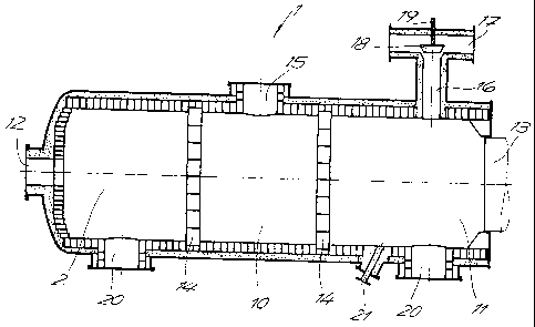
Fig. 2 the fission reactor in a representation that is
enlarged as compared with Fig. 1.
Hydrogen sulfide is converted to elemental sulfur in the Claus
plant shown in Fig. 1. The fundamental structure of the plant
includes a fission reactor 1 having a combustion chamber 2 and a
catalyst bed 3, a waste heat boiler 4 connected with the gas
outlet of the fission reactor 1, as well as at least one
catalyst stage 5. An acid gas 6 containing hydrogen sulfide,
along with air 7 and heating gas 8, is introduced into the
combustion chamber 2 of the fission reactor 1. In an exothermic
reaction, part of the hydrogen sulfide is converted to elemental
sulfur on the catalyst. The process gas leaves the fission
reactor 1 at a temperature of approximately 1200 C, and is
cooled to a temperature of less than 170 C, which is required
for condensation of the sulfur, in the waste heat boiler 4. The
condensing sulfur is precipitated. After precipitation of the
sulfur, the cooled process gas is heated and passed to the
catalyst stage 5, in which sulfur compounds are converted to
elemental sulfur on a catalyst. The catalyst stage 5 is
operated at a temperature of less than 300 C. The process gas
leaving the catalyst stage 5 is also cooled to the temperature

CA 02492340 2005-01-12
6
required for condensation of the sulfur, in the waste heat
boiler 4, and the condensed sulfur is precipitated.
It is evident from a comparison of Figures 1 and 2 that the
fission reactor 1 consists of a horizontal, cylindrical boiler 9,
lined with refractory material, in which boiler the combustion
chamber 2, a catalyst chamber 10 for the catalyst bed 3, as well
as a chamber 11 on the outflow side are disposed next to one
another. An inflow opening 12 for a mixture of heating gas, air,
and acid gas containing H2S, as well as a gas outlet 13 for a hot
process gas containing elemental sulfur are disposed on the
opposite faces of the boiler 9. The catalyst chamber 10 is
delimited, on both sides, by gas-permeable checker bricks 14
made of refractory material, and has a mantle-side fill opening
15 for introduction of the catalyst bed. It is practical if the
checker bricks 14 contain elongated holes. A branch line 16
lined with refractory material is connected on the circumference
of the chamber on the outflow side, which line opens into a
process gas line 17 adjacent to the boiler. The process gas
line 17 connects the gas outlet of the waste heat boiler 4 with
the catalyst stage 5, and has a process gas flowing through it,
which exits from the waste heat boiler 4 at a temperature of
less than 170 C, and is heated to a working temperature between

CA 02492340 2005-01-12
7
210 C and 250 C before entry into the catalyst stage 5. The
heating takes place by mixing in hot process gas that flows in
through the branch line 16. In the opening region of the branch
line 16, a valve body 18 is disposed, in adjustable manner, with
which the amount flow of the hot gas stream exiting from the
branch line 16 can be regulated. The valve body 18 and a
setting device 19 assigned to the valve body are cooled by the
cooler process gas that flows through the process gas line 17,
so that usual metallic materials can be used.
The fission reactor furthermore has cleaning and inspection
openings 20, as well as an access 21 for a temperature
measurement device.
The waste heat boiler 4 has a steam generator chamber surrounded
by a pressure-resistant mantle, to which chamber a feed device
22 for boiler feed water as well as an exhaust device 23 for
low-tension steam are connected. The waste heat boiler 4
contains a long tube bundle of heat exchanger tubes, which
extend through the steam generator chamber and are inserted, on
both ends, into tube plates that delimit the steam generator
chamber. Furthermore, at least one additional tube bundle of
shorter heat exchanger tubes is provided, which are also

CA 02492340 2005-01-12
8
inserted into the tube plate at their exit-side end, and open
into an inflow chamber 24 at the entry-side end. The long tube
bundle has a hot process gas that exits from the fission reactor
flowing through it. The inflow chamber 24 is disposed within
the steam generator chamber and is impacted by a cooler process
gas from the catalyst stage 5. The waste heat boiler 4
furthermore has a head piece 25 that follows the tube plate on
the exit-side end, and is divided into sections. Each section
of the head piece 25 has a tube bundle assigned to it, in each
instance. Devices for drawing off condensed sulfur are
connected with the sections.

Representative Drawing
A single figure which represents the drawing illustrating the invention.
Administrative Status

2024-08-01:As part of the Next Generation Patents (NGP) transition, the Canadian Patents Database (CPD) now contains a more detailed Event History, which replicates the Event Log of our new back-office solution.

Please note that "Inactive:" events refers to events no longer in use in our new back-office solution.

For a clearer understanding of the status of the application/patent presented on this page, the site Disclaimer , as well as the definitions for Patent , Event History , Maintenance Fee  and Payment History  should be consulted.

Event History

Description Date
Time Limit for Reversal Expired 2019-05-10
Letter Sent 2018-05-10
Grant by Issuance 2011-11-01
Inactive: Cover page published 2011-10-31
Inactive: Final fee received 2011-08-16
Pre-grant 2011-08-16
Notice of Allowance is Issued 2011-03-17
Letter Sent 2011-03-17
Notice of Allowance is Issued 2011-03-17
Inactive: Approved for allowance (AFA) 2011-03-15
Amendment Received - Voluntary Amendment 2010-10-06
Inactive: S.30(2) Rules - Examiner requisition 2010-04-08
Amendment Received - Voluntary Amendment 2008-07-17
Letter Sent 2008-04-15
Request for Examination Received 2008-02-04
Request for Examination Requirements Determined Compliant 2008-02-04
All Requirements for Examination Determined Compliant 2008-02-04
Letter Sent 2005-04-28
Inactive: IPRP received 2005-03-31
Inactive: Single transfer 2005-03-21
Inactive: Cover page published 2005-03-16
Inactive: Courtesy letter - Evidence 2005-03-15
Inactive: Notice - National entry - No RFE 2005-03-12
Application Received - PCT 2005-02-10
National Entry Requirements Determined Compliant 2005-01-12
Application Published (Open to Public Inspection) 2004-02-19

Abandonment History

There is no abandonment history.

Maintenance Fee

The last payment was received on 2011-04-21

Note : If the full payment has not been received on or before the date indicated, a further fee may be required which may be one of the following

  • the reinstatement fee;
  • the late payment fee; or
  • additional fee to reverse deemed expiry.

Patent fees are adjusted on the 1st of January every year. The amounts above are the current amounts if received by December 31 of the current year.
Please refer to the CIPO Patent Fees web page to see all current fee amounts.

Owners on Record

Note: Records showing the ownership history in alphabetical order.

Current Owners on Record
UHDE GMBH
Past Owners on Record
HOLGER THIELERT
Past Owners that do not appear in the "Owners on Record" listing will appear in other documentation within the application.
Documents

To view selected files, please enter reCAPTCHA code :


To view images, click a link in the Document Description column. To download the documents, select one or more checkboxes in the first column and then click the "Download Selected in PDF format (Zip Archive)" or the "Download Selected as Single PDF" button.

List of published and non-published patent-specific documents on the CPD .

If you have any difficulty accessing content, you can call the Client Service Centre at 1-866-997-1936 or send them an e-mail at CIPO Client Service Centre.


Document
Description 
Date
(yyyy-mm-dd) 
Number of pages   Size of Image (KB) 
Description 2005-01-11 8 257
Abstract 2005-01-11 1 21
Representative drawing 2005-01-11 1 18
Drawings 2005-01-11 2 38
Claims 2005-01-11 2 61
Drawings 2010-10-05 2 35
Description 2010-10-05 8 254
Claims 2010-10-05 1 45
Abstract 2011-03-16 1 21
Representative drawing 2011-09-25 1 13
Reminder of maintenance fee due 2005-03-13 1 111
Notice of National Entry 2005-03-11 1 194
Courtesy - Certificate of registration (related document(s)) 2005-04-27 1 104
Reminder - Request for Examination 2008-01-13 1 118
Acknowledgement of Request for Examination 2008-04-14 1 177
Commissioner's Notice - Application Found Allowable 2011-03-16 1 163
Maintenance Fee Notice 2018-06-20 1 180
PCT 2005-01-11 9 309
Correspondence 2005-03-11 1 26
PCT 2005-01-12 3 128
PCT 2005-01-11 1 46
Correspondence 2011-08-15 1 30