Note: Descriptions are shown in the official language in which they were submitted.
CA 02492613 2005-O1-14
WO 2004/010760 PCT/US2003/022773
1
MICROFLUIDIC SIZE-EXCLUSION
DEVICES, SYSTEMS, AND METHODS
CROSS REFERENCE TO RELATED APPLICATIONS
[0001] This application claims priority benefit from: U. S. Patent
Applications Nos.
10/336,274, 10/336,330, and 10/336,706, all filed January 3, 2003; U.S. Patent
Applications Nos. 10/403,640 and 10/403,652, both filed March 31, 2003; U.S.
Provisional Patent Applications Nos. 60/398,851 and 60/398,946, both filed
July 26, 2002;
and U.S. Provisional Patent Application No. 60/399,548, filed July 30, 2002.
All of the
Applications cross-referenced herein are incorporated herein in their
entireties by reference.
FIELD
[0002] The present application relates to microfluidic devices, systems that
include
such devices, and methods that use such devices and systems. More particularly
the present
invention relates to devices that manipulate, process, or otherwise alter
micro-sized amounts
of fluids and fluid samples.
BACKGROUND
[0003] Microfluidic devices are useful for manipulating fluid samples. There
continues to exist a demand for microfluidic devices, systems of using them,
systems for
processing them, and methods of manipulating fluids, that are fast, reliable,
consumable, and
can be used to process a large number of samples simultaneously.
SUMMARY
[0004] According to various embodiments, a microfluidic device is provided
that
includes a substrate, a first channel, a second channel, a column connecting
the first and
second channels, and a~filter frit material disposed in the colLUnri. The
substrate can have first
and second opposing surfaces and a thickness. The first channel can be formed
in the first
surface and can have a first depth extending in a direction normal to the
first surface and
toward the second surface. The first depth can be equal to or less than the
thickness of the
substrate. The second channel can be formed in the second surface and can have
a second
depth extending in a direction normal to the second surface and toward the
first surface. The
second depth can be equal to or less than the thiclrness of the substrate. The
column can have
a height that extends from the first surface to the second surface. The column
can have a
constant cross-sectional area and/or a constant diameter, along planes that
lie parallel to the
first surface, from the first surface to the second surface.
CA 02492613 2005-O1-14
WO 2004/010760 PCT/US2003/022773
2
[0005] According to various embodiments, an integrated gel filtration ~frit is
provided that
includes a body comprising a form-stable filter frit material, a chamber
formed in the body,
and a gel filtration material disposed in the chamber.
[0006] According to various embodiments, a microfluidic device is provided
that
includes a substrate, a first channel, a second channel, a fluid communication
between the
first channel and the second channel, and a flow-restricting particulate
material piled-up or~
log jammed at the fluid communication. According to such embodiments, the
substrate can
have a first surface, a second surface opposing the first surface, and a
thickness. The first
channel can be formed in the substrate and can extend in a first direction.
The first channel
can have a first cross-sectional area defined by at least a first minimum
dimension and a first
depth, the first depth extending in a direction normal to the first surface
and toward the
second surface. The second channel can be formed in the substrate and can
extend in a
second direction. The second channel can have a second cross-sectional area
defined by at
least a second minimum dimension and a second depth, the second depth
extending in a
direction normal to the first surface and toward the second surface. The fluid
communication
can be formed in the substrate between the first channel and the second
channel and can have
a third cross-sectional area defined by at least a third minimum dimension,
where the third
cross-sectional area is less than the first cross-sectional area. The flow-
restricting material
can be disposed in the first channel, in the fluid communication, or in both
the first channel
and in the fluid communication. The flow-restricting material can include gel
filtration
particles, where at least 10% by weight of the flow-restricting particles
comprises flow-
restricting particles having an average particle diameter that is less than
the third minimum
dimension.
[0007] According to various embodiments, a microfluidic device is provided
that
includes a substrate, a first channel formed in the substrate, and a first
chamber formed in the
substrate, wherein the first chamber has a depth and a teardrop-shaped cross-
sectional area
when cross-sectioned perpendicular to the depth The first chamber can have a
substantially
circular first end and a narrower and opposite second end, which ends
collectively define a
teardrop-shaped cross-section. The cross-section of the first chamber can be
constant along
the depth of the first chamber. The second end of the first chamber can be in
fluid
communication with the first channel.
[0008] According to various embodiments, a microfluidic device is provided
that
includes a substrate having a first surface, a second surface opposing the
first surface, and a
CA 02492613 2005-O1-14
WO 2004/010760 PCT/US2003/022773
3
thiclness, and a plurality of parallel pathways formed in the substrate,
wherein each of the
pathways comprises an input opening, an output opening, at least one
processing chamber
located between the input opening and the output opening, and wherein the
input opening, the
at least one processing chamber, and the output opening at each pathway are
arranged
linearly. Each of the plurality of parallel pathways can include at least one
valve that is
capable of being actuated to provide a fluid communication between the at
least one
processing chamber and at least one of the input opening and the output
opening. Each of the
plurality of pathways can include at least one valve that comprises a first
deformable material
having a first elasticity, a second deformable material having a second
elasticity that differs
from the first elasticity, and an adhesive material.
[0009] According to various embodiments, a sample processing system is
provided that
includes a microfluidic device as described herein, a platen, a drive unit,
and a control unit
wherein the platen includes a microfluidic device holder to hold the
microfluidic device. The
microfluidic device can have a substrate having a first surface, a second
surface opposing the
first surface, and a thickness, and a plurality of parallel pathways formed in
the substrate,
each of the pathways comprising an input opening, an output opening, and at
least one
processing chamber between and in fluid communication v~rith the input opening
and the
output opening. The platen can have an axis of rotation and the holder can be
disposed.spaced
from, and ofF center with respect to, the axis of rotation. The drive unit can
be capable of
rotating the platen about the axis of rotation, and the control unit can be
capable of
controlling the drive unit.
[00010] According to various embodiments, a method of fabricating a
microfluidic device
is provided, wherein the microfluidic device includes a substrate, an input
opening formed in
the substrate, a first channel formed in the substrate and in fluid
communication with the
input opening, a second channel formed in the substrate, and a fluid
communication between
the first channel and the second channel. The method can include introducing a
flow-
restricting material through the input opening and into the first channel, and
applying
centripetal force to the microfluidic device to pack the flow-restricting
material in the first
channel at the fluid communication and to prevent a substantial portion of the
flow-restricting
material from moving through the fluid communication and into the second
channel.
[00011] According to various embodiments, a microfluidic device is provided
having a
substrate, a first recess formed in the substrate, a second recess formed in
the substrate, and
an intermediate wall interposed between the first recess and the second
recess, wherein the
CA 02492613 2005-O1-14
WO 2004/010760 PCT/US2003/022773
4
intermediate wall portion is formed 'from a deformable material having a first
elasticity. An
elastically deformable cover layer is also provided covering the first recess,
and a particulate
flow-restricting material can be disposed in the first recess. The elastically
deformable cover
layer can have a second elasticity that is less than the first elasticity,
wherein the elastically
deformable covered layer contacts the intermediate wall when the intermediate
wall is in a
non-deformed state, and wherein the elastically deformable cover layer does
not contact the
intermediate wall when the intermediate wall is in a deformed state, thereby
forming a fluid
communication between the first and second recesses. The fluid communication
between the
first and second recesses can be designed or formed as a flow restrictor as
described herein.
[00012] The teachings herein may be more fully understood with reference to
the
accompanying drawing figures and the descriptions thereof. Modifications that
would be
recognized by those skilled in the art are considered a part of the present
teachings.
BRIEF DESCRIPTION OF THE DRAWINGS
[00013] Fig. 1 is a top view of a microfluidic device according to an
embodiment wherein
a first channel is formed in a first surface, a second channel is formed in a
second surface,
and an interconnecting column of constant diameter and having a frit material
disposed
therein;
[00014] Fig. 2 is a cross-sectional side view of the microfluidic device shown
in Fig. 1
taken along line 2-2 of Fig. l;
[00015] Fig. 3 is a top view of another embodiment of a microfluidic device
including an
integrated gel filtration frit;
[00016] Fig. 4 is a cross-sectional side view of the microfluidic device shown
in Fig. 3
taken along line 4-4 of Fig. 3;
[00017] Fig. 5 is a top view of a inicrofluidic device according to an
embodiment
including an integrated gel filtration fi-it;
[00018] Fig. 6 is a cross-sectional side view of the microfluidic device shown
in Fig. 5
taken along line 6-6 of Fig. 5;
[00019] Fig. 7 is a perspective view of an integrated gel filtration frit
having a form-stable
body, a chamber in the body, and a gel filtration material disposed in the
chamber;
[00020] Fig. 8 is a cross-sectional side view of an integrated gel filtration
frit including
a form-stable body as shown in Fig. 7 being filled with a gel filtration
material by using a
nozzle;
CA 02492613 2005-O1-14
WO 2004/010760 PCT/US2003/022773
[00021] Fig. 9 is a perspective view of a form-stable body for use in
preparing an
integrated gel filtration frit and having a chamber;
[00022] Fig. 10 is a cross-sectional side view of the form-stable body shown
in Fig. 9
being filled with a gel filtration material by using a nozzle;
[00023] Fig. 11 is a perspective view of a mufti-nozzle machine useful in
filling a plurality
of integrated gel filtration frits simultaneously;
[00024] Fig. 12 is a top view in partial cross-section of a microfluidic
device that includes
a fluid communication having a conical shape, and including two types of
particles sizes;
[00025] Fig. 13 is a top view in partial cross-section of an embodiment of a
side view of
a microfluidic device including a gel filtration material that can be used as
a flow
restrictor;
[00026] Figs. 14 and 15 are top views in partial cross-section of embodiments
of a
microfluidic device having baffles to restrict the flow of fluid and cause a
pile-up of gel.
filtration particles;
[00027] Figs. 16 and 17 are top views of various embodiment of a microfluidic
device
including a fluid communication having an abrupt change in the cross-sectional
area
between a first channel and a second channel;
[00028] Fig. 18 is a flowchart with corresponding cross-sectional views,
depicting a
method for forming a microfluidic device;
[00029] Fig. 19 is a flowchart depicting a method of preparing a microfluidic
device for
use as a purification device;
[00030] Fig. 20 is a top view of an embodiment of a microfluidic device having
a
substrate, a plurality of parallel pathways formed in the substrate, and a
plurality of valves for
_ each pathway; . _ _ . _. .
[00031] Fig. 21 is a perspective view of an embodiment of a substrate having a
plurality of
pathways;
[00032] Fig. 22 is a top view of an embodiment that includes a plurality of
teardrop-
shaped chambers arranged on a cant and formed in a substrate;
[00033] Fig. 23 is an enlarged perspective view of an embodiment of a teardrop-
shaped
input chamber having atapering cross-section;
[00034] Fig. 24 is a top view of a microfluidic device according to an
embodiment having
a pathway for processing a sample;
CA 02492613 2005-O1-14
WO 2004/010760 PCT/US2003/022773
6
[00035] Fig. 25 is an enlarged perspective view of the pathway shown in the
device of
Fig. 24;
[00036] Fig. 26 is a perspective view of an embodiment of a microfluidic
system
comprising microfluidic devices held on a rotatable platen that can be rotated
by a drive unit,
heated by a heating element, and controlled by a control unit;
.[00037] Figs. 27a-27d are cross-sectional views of a microfluidic channel
having various
profiles in the substrate;
[00038] Fig. 28 is an exploded perspective view of an assembly including a
sample
processing device and a carrier;
[00039] Fig. 29 is a perspective view of the assembly of Fig. 28 as assembled;
[00040] Fig. 30 is an enlarged view of a portion of a carrier depicting one
set of main
conduit support rails and collars useful in isolating the process chambers on
a sample
processing device;
[00041] Fig. 31 is a partial cross-sectional view of a portion of a carrier
illustrating an
example of a force transfer structure useful within the carrier;
[00042] Fig. 32 is a partial cross-sectional view of a carrier and sample
processing
device assembly including an optical element in the carrier;
[00043] Fig. 33 depicts a carrier and sample processing device assembly
including an
alignment structure for a sample processing delivery device;
[00044] Fig. 34 is an exploded perspective view of another sample processing
device
and can-ier assembly according to various embodiments; and
[00045] Fig. 35 is a blocl: diagram of a thermal processing system that can be
used in
connection with sample processing devices.
[00046] Other various embodiments of the present invention -will be apparent
to those
skilled in the art from consideration of the specification and practice of the
devices, systems,
and methods described herein, and the detailed description that follows. It is
intended that the
specification and examples be considered as exemplary only, and that the true
scope and
spirit of the invention includes those other various embodiments.
DETAILED DESCRIPTION OF CERTAIN EMBODIMENTS
[00047] Fig. 1 is a top view of a microfluidic device 98 according to various
embodiments
that include a substrate 100, an input opening 102, an output opening 110, a
first channel 104,
a second channel 108, a chamber 106 interconnecting the first channel 104 and
the second
CA 02492613 2005-O1-14
WO 2004/010760 PCT/US2003/022773
7
channel 108, and a filter fi-it material 112 disposed in the chamber 106. The
chamber 106 can
be in the form of a column, for example, a vertical cylindrical column as
shown.
[00048] Fig. 2 is a cross-sectional side view of the microfluidic device 98 of
Fig. 1, taken
along line 2-2 of Fig. 1. As shown in Figs. l and 2, covers 114, 116, and 118
are provided in
contact with the substrate 100. Cover 114 covers the bottom, as shown in
Fig.2, of the
substrate 100 and provides an inner surface 115 that can, in-part, define
channel 104. A fluid
sample introduced in input opening 102 can pass from input opening 102 into
first channel
104, through first channel 104 and into chamber 106, through filter fi-it
material 112 in
chamber 106 and into second channel 108, and from second channel 108 into
output opening
110. First channel 104 can be loaded with a gel filtration material (not
shown), for example,
an ion-exchange gel filtration material.
[00049] Input opening 102 can be designed as an entry port, a hole through a
layer, an
aperture, or any other feature that provides an entrance to a channel or
chamber in fluid
communication therewith. Output opening 110 can be designed as a port,
aperture, a hole
through a layer, or any other feature that provides an exit from a channel or
chamber in fluid
communication therewith. Input opening 102 and/or output opening 110 can be
covered or
partially covered by a frangible or puncturable material cover 116,118 that
can be in the form
of a tape, a film, a sheet, a membrane, or a combination thereof. Cover 114
for the bottom
(as shown) of the device can be a tape, a film, a sheet, a membrane, or a
combination thereof.
Any of covers 114, 116, and 118 can be in the form of a second substrate
affixed to, secured
to, bonded to, or otherwise connected to the substrate 100. First channel 104,
second channel
108, chamber 106, or combinations thereof can be pre-filled with reagents,
reactants, or
buffers known in the art, before the respective cover is applied to substrate
100.
Additionally, first channel 104, second channel 108, chamber 106, or
combinations thereof
can be loaded through the input opening.
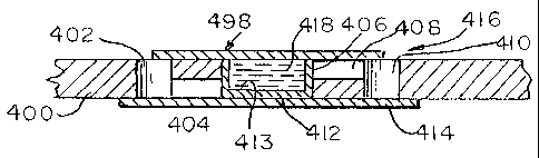
[00050] Fig. 3 is a top view of a microfluidic device 498 that includes a
filter frit material
412 having a shape that complements the shape of a column 406 iz1 which the
filter frit
material 412 is disposed. The filter fi-it material 412 can include a chamber
413 that retains a
gel filtration material 418. Fig. 4 is a side view of the microfluidic device
498 shown in Fig.
3. In the embodiment shown in Figs. 3 and 4, the device fixrther includes a
substrate 400, an
input opening 402, a first channel 404, a chamber 406 for accommodating filter
fi-it :material
412, a second channel 408, and an output opening 410. The device 498 shown in
Figs. 3 and
CA 02492613 2005-O1-14
WO 2004/010760 PCT/US2003/022773
8
4 can also include a first cover 414, and a second cover 416. The filter frit
material 412 can
have an outer shape that is complementary to the inner shape of chamber 406.
[00051] Figs. 5 and 6 show an embodiment of a microfluidic device 700 that
includes a
substrate 701 and a filter frit material 712 having a shape that complements a
chamber 713.
An opening 720 of the filter frit material 712 faces an input opening 702
formed in substrate
701. The filter frit material 712 further includes a closed end 722 oriented
towards an output
opening 710 formed in a substrate 701. The filter frit material 712 can be
filled with a
filtration material 718, for example, an ion-exchange gel filtration material.
Covers 714 and
716 can be secured, bonded, adhered, or otherwise affixed to substrate 701
using an adhesive
715. The adhesive can be, for example, a pressure sensitive adhesive.
[00052] The microfluidic devices 98, 498, and 700 shown in Figs. 1-6 can be
used for
filtering liquids that are manipulated to pass through the devices. The
devices can be used,
for example, for gel filtration, size-exclusion filtration, ion-exchange
filtration, or
combinations of these filtration techniques. For example, filtration materials
can be loaded
and/or included in the devices, and can include small beads of filtration
materials. Size-
exclusion materials can be used that can retain smaller molecules of an
aqueous sample while
allowing larger molecules of the sample to pass through or around. For
example, P-10 BIO-
GEL materials from Bio-Rad can be used and are composed of acrylamide
particles that are
roughly 45-90 ~,m in average particle size diameter. These particles, when
hydrated, can
capture free dyes, undesired nucleotides, and salt ions from a sample as the
sample migrates
through the materials.
[00053] Samples can be manipulated through devices 98, 498, and 700 by gravity
pressure
differentials, or centripetal force, for example. The resulting filtrates that
elute from the
-- - devices can then be analyzed, used, or subsequently -passed on through
the device to a
subsequent stage of processing, for example, into a PCR reaction chamber, a
sequencing
reaction chamber, or other processing reaction chamber.
[00054] According to various embodiments, the filter frit material 112, 412,
or 712 shown
in Figs. 1-6 can be ''press fit" into the respective chamber, placed in the
respective chamber,
or otherwise positioned in the respective chamber.
[00055] The covers described above with reference to Figs. 1-6 can include a
plastic
material, for example, a polyolefin material. According to various
embodiments, covers can
include tape or film materials coated with a pressure-sensitive adhesive, or
plastic materials
that can be thermally bonded to a respective substrate.
CA 02492613 2005-O1-14
WO 2004/010760 PCT/US2003/022773
9
[00056] According to various embodiments including those shown in Figs. 1-6,
the device
can include one or more channels that can be rectangular in cross-sectional
shape. The
devices can include channels that can be, for example, from about 0.1 mm to
about 1.0 cm
deep, from about 0.1 mm to about 1.0 cm wide, and from about 0.1 mm to about
10.0 cm
long. An exemplary channel can be 0.50 mm deep, 0.50 mm wide, and 20 mm long,
thus
providing total volume of about 5 uL.
[00057] According to various embodiments including those of Figs. 1-6, a gel
filtration
material can be disposed in a channel of the device. The gel filtration
material can be loaded
into the device by pipetting into an input opening of the device and/or
drawing the material
into the device by using vacuum force, for example, applied to an output
opening of the
device. A channel of the device can be filled with a gel filtration material
by pressure loading
the gel filtration material tlll-ough an input opening of the device to
dispense the gel filtration
material in a channel or chamber of the device. In an exemplary embodiment, a
fully
hydrated gel filtration material is loaded into a channel of the device, for
example, into first
channel 104 of device 98 of Fig. 1. Once the channel is filled with hydrated
gel filtration
material, the device can be centrifuged to de-water the gel filtration
material and to "pack"
the gel filtration material, forming a purification column. This process can
be used to prepare
the device for sample filtration and can be used to remove mmecessary or
excess water or
buffer from the gel filtration material. In a variant of this process, the
excess water or buffer
can be collected in an outlet channel or chamber and later used to dilute and
increase the
volume of a filtered sample to render the sample injection-ready.
[00058] According to various embodiments including the embodiments of Figs. 1-
6, the
device can include additional chambers and/or channels. For example, the
device can include
a PCR amplification chamber, a sequencing reaction chamber, or both a PCR
amplification
chamber and a sequencing reaction chamber. According to various embodiments,
the device
can include an output chamber useful for holding a sample prior to injecting
the sample into a
sequence detection system or other analytical detector.
[00059] According to various embodiments, microfluidic devices are provided
that
include a plurality of sample processing pathways as described herein, in a
single device.
[00060] According to various embodiments, a porous filter fi-it material can
be used to
prevent the gel filtration material loaded in a channel from flowing out of
the channel. The
average pore size of the filter frit material can be chosen to allow fluids to
pass through
(water, sample, etc.) while constraining the movement of a gel filtration
material such as
CA 02492613 2005-O1-14
WO 2004/010760 PCT/US2003/022773
acrylamide beads. For instance, the microfluidic device shown in the Figs. 1-6
can utilize a
hydrophilic polyethylene filter frit material with an average pore size of
about 33 microns.
When used with P-10 BIO-GEL gel filtration materials, such a fi-it can
adequately constrain
the gel filtration materials while allowing water and sample fluids to pass
therethrough An
exemplary porous filter fi-it material that can be used for such purpose is a
sintered, high-
density polyethylene (HDPE) frit having a suitable average pore size.
[00061] According to various embodiments, a gel filtration retention mechanism
can be
provided in a device and includes a flow-restrictor in the form of a small
channel or
serpentine path formed in the substrate and which prevents the gel filtration
material from
passing.
[00062] According to various embodiments including the embodiments of Figs. 1-
4,
wherein two channels are provided and separated by a filtration chamber or
column, one of
the channels can be formed in a first surface of a substrate and a second
channel can be
formed in the opposing surface of the substrate. For example, the second
channel 108 (Fig.
2) or 408 (Fig. 4) can be formed in a first surface of the substrate and can
provide fluid
communication between a processing chamber and a respective output opening.
[00063] The second channel can have dimensions similar to, or the same as, the
dimensions of the first channel, as illustrated in Figs. 3 and 4. The second
channel can have a
depth of from about 0.1 mm to about 1.0 cm, a width of from about 0.1 mm to
about 1.0 crn,
and a length of from about 0.1 mrn to about 10.0 cm. An exemplary second
channel has a
depth of about 0.50 mm, a width of about 0.75 mm and a length of about 3.0 mm.
The
second channel can be at least partially defined by a cover, for example,
cover 116 shown in
Figs. 1 and 2, or figure 416 shown in Figs. 3 and 4. Regardless of whether the
device
includes a first channel filled with a gel filtration material, the second
channel of the device
can be provided with a gel filtration material loaded therein. Gel filtration
material can be
loaded into the second channel before, after, or at the same time that a
filtration frit is
positioned within the device.
[00064] According to various embodiments, the output opening 110, 410, 710 can
serve to
capture or retain a processed sample after the sample passes through a
processing chamber in
the microfluidic device. Initially, the output opening 110, 410, 710 can be
open so that
vacuum can be applied to the device for loading a gel filtration material. The
output opening
can remain open during centrifugation of the microfluidic device to fizrther
pack and/or
dewater the gel filtration material. During such a packing process, excess
water or buffer can
CA 02492613 2005-O1-14
WO 2004/010760 PCT/US2003/022773
11
be purged from the device and can escape the device through the outlet opening
110, 410,
710. When a sample is manipulated through the microfluidic device, as by
centrifugation, for
example, the outlet opening 110, 410, 710 can be sealed with a cover film 116,
416$ 716 to
prevent the sample from being lost, or to otherwise retain the sample in the
device.
[00065] According to various embodiments, a microfluidic device can be
provided with a
plurality of pathways formed in a substrate, with each pathway being similar
to one of the
pathways shown in Fig. 1-6. Using channels and chambers having widths of about
0.50 mm
or less, for example, it is possible to provide up to 96 or more such pathways
in the substrate
and to provide a resulting substrate size equivalent to that of a standard
micro-titer tray, for
example, a length of about 4.75 inches and a width of about 3.25 inches. An
exemplary
device of such design is shown in Fig. 20 and incorporates the 5 ~,L gel
filtration columns.
[00066] According to various embodiments, a microfluidic device is provided
similar to
those shown in Figs. 1-4 and having a substrate that includes a thickness that
is greater than
the sum of the depth of the first channel and the depth of the second channel.
According to
various embodiments, a microfluidic device is provided similar to the device
shown in Figs. 5
and 6 and having a substrate that includes a thiclness that is the same as the
depth of the filter
chamber 713.
[00067] According to various embodiments, including the embodiments of Figs. 1-
6, a
microfluidic device is provided wherein the filtration frit material 112, 412,
712 has an outer
peripheral shape, the chamber 106, 406, 713 has an inner peripheral shape, and
the outer
peripheral shape is complementary to the inner peripheral shape.
[00068] Figs. 7 and 9 depict exemplary embodiments of an integrated gel
filtration frit
750, 950 that includes a body 712, 772 made up of a form-stable frit material
and that defines
a chamber 721, 921 and an opening 728, 928. The chamber 721, 921 is filled
with a gel
filtration material 778, 978 that has been loaded in the chamber 721, 921. The
gel filtration
frit 750, 950 can be made by a method as depicted in Figs. 8 and 10,
respectively.
[00069] Figs. 8 and 10 illustrate a nozzle 130 in the process of filling the
integrated gel
filtration frits 750, 950 with a diluent 132 and a gel filtration material
778, 978 via the
opening 728, 928.
[00070] Fig. 11 depicts an embodiment of a mufti-nozzle filling machine 140
for
simultaneously filling a plurality of integrated gel filtration frits.
[00071] According to various embodiments, an integrated gel filtration frit
750, 950 can
be formed as illustrated in Figs. 8 and 10 and subsequently packed into a
microfluidic device,
CA 02492613 2005-O1-14
WO 2004/010760 PCT/US2003/022773
12
for example, a device as shown in Figs. 3-6. For instance, a slurry of
hydrated P-10 BIO-
GEL particles can be pumped into a porous form-stable frit body, and the
resulting frit can be
assembled into a microfluidic device. Such a manufacturing procedure can
reduce the
number of substrate manipulations involved with forming the microfluidic
device, allow for
off line filtration fi-it fabrication, and can reduce the overall
manufacturing costs for the
microfluidic device.
[00072] According to various embodiments, the body and/or chamber of the
integrated
gel filtration frit can be constructed in a rectanguloid or a cylindrical
shape, and the .
chamber can be pre-filled with more than one type of gel using a single nozzle
or multiple
nozzles.
[00073] The integrated gel filtration frit can retain a gel filtration
material therein yet
allow water and liquid samples to flow therethrough.
' [00074] According to various embodiments, an integrated gel filtration frit
can be
provided that includes an opening in a frit body which is in fluid
communication with an
interior gel filtration material chamber. According to various embodiments, an
integrated gel
filtration fi-it can be provided having a gel filtration material that
includes an ion-exchange
gel filtration material. According to various embodiments, an integrated gel
filtration. fi-it can
be provided having a form-stable filter frit body that includes a porous
hydrophilic
polyethylene material. The body could also be formed using a membrane or other
filter
materials, and does not necessarily have to be form-stable. The integrated gel
filtration frit
can have a length dimension, a width dimension, and a depth dimension, wherein
each of the
dimensions is less than 50 mm.
[00075] According to various embodiments, a microfluidic device is provided
having a
- channel formed in a substrate and an integrated gel filtration fi-it
disposed in the channel, for
example, as shown in Fig. 6. According to various embodiments, a microfluidic
device can
be provided having a channel formed in a substrate, an input opening formed in
the substrate,
an output opening formed in the substrate, a filtration column or chamber
formed in the
substrate between and in fluid communication with the input opening and the
output opening,
and an integrated gel filtration frit as described herein disposed in the
column, wherein the
input opening of the channel is in fluid communication with the opening of the
integrated gel
filtration fi-it.
[00076] Figs. 12-16 depict various microfluidic devices 200, each of which is
designed
with one or more features for restricting the flow of a filtration material
through the device.
CA 02492613 2005-O1-14
WO 2004/010760 PCT/US2003/022773
13
In Figs. 12 and 14-16, the features are formed in a substrate 220. In the
device of Fig. 13, the
channels can be formed in an insertable component that can be incorporated
into a
rnicrofluidic device. In each device, a first channel 208 is in fluid
communication with a
second channel 210. A fluid communication 212 in the form of a region is
provided in each
device between the first channel 208 and the second channel 210. In Figs. 12
and 14-16, the
fluid communications 212 are also formed in the substrate 220. Each of Figs.
12-16 shows
flow-restricting material 202 disposed in the first channel 208 and/or the
fluid
communication 212. As shown in Figs. 12 and 13, a second material 204 of
smaller average
diametrical particle cross-section area than material 202 is provided in first
channel 208. In
Fig. 13, a third material 206 having an even smaller average diametrical
particulate cross-
sectional area is provided in first channel 208. Each of the materials 202,
204, and 206 can
include a gel filtration material, such as, an ion-exchange gel filtration
material. Each of the
,materials 202, 204, and 206 can be an inert material having an average
diametrical particle
cross-sectional area as described herein, for example, glass or silicon seeds.
The microfluidic
device 200 can also have baffles 214 as depicted in Figs. 14 and 15, to
further restrict the
flow of the flow-restricting material 202 into the second channel 210. The
baffles 214 can be
provided in the fluid communication 212, in the second channel 210, or in both
the fluid
communication 212 and in the second channel 210.
[00077] Some of the particles of materials 202, 204, and 206 can flow into the
second
channel 210 before a pile-up of the materials 202, 204, and 206 forms at fluid
communication
212. The forniing of the pile-up and/or the breakdown of the pile-up at the
fluid
communication 212 can be manipulated by controlling how much force is applied
to the
microfluidic device, for example, a centripetal force, or a pneumatic force.
The fluid
communication 212 can be a tapered transition region, for example, a funnel-
shaped
transition region. The fluid communication 212 can be a conically-shaped
transition region
as depicted in Figs. 12-15.
[00078] According to various embodiments, a method to form a microfluidic
device
200 as depicted in any one of Figs. 12-15 is provided. Particulate flow-
restricting material
202 is disposed in a first channel 208 having a first cross-sectional area.
The first channel
208 terminates at a fluid communication 212 in the form of a region. The
particles of the
first material 202 can have an average diametrical particle cross-sectional
area that is from
5% to about 90% of the diametrical cross-sectional area of the second channel
210.
According to various embodiments, an additional material 204 made-up of
particles
CA 02492613 2005-O1-14
WO 2004/010760 PCT/US2003/022773
14
having a smaller cross-sectional area than the first material particles can
then be added to
the pile-up of the first material particles 202. A third type of material 206
can be added
after particulate material 204, the third material 206 can be another flow-
restricting
particulate material, can be of the same composition but of smaller size than
either
particulate material 202 or 204, or can be a gel or resin material that can be
non-
particulate. Diluent initially accompanying or used to load the first and/or
second material
can be removed from the first channel 208 through the fluid communication 212
and into
the second channel 210, for example, by using centripetal force. The diluent
can further
be removed from the second channel 210 and, for example, removed from the
device or
stored in a collection or output chamber.
[00079] According to various embodiments, the particulate materials 202, 204,
and 206
can be gel filtration particles or other particles. The particles can be
chemically derivitized
or physically modified to provide functions other than restricting flow of
subsequently
loaded gel or resin materials. For example, the materials 202, 204, and 206
can be
modified to allow hybridization with DNA or DNA fragments. In cases where any
of
materials 202, 204, or 206 are modified to allow hybridization, methods can be
provided
whereby hybridized components can subsequently be released from the materials,
for
example, by denaturing. As such, various embodiments can provide a
purification or
concentration of hybridizable components. '
[00080] Because the microfluidic devices 200 shown in Figs. 12-16 can be
assembled
in place, methods of making the devices can avoid access and handling problems
associated with using filtration frits known in the art. For example, the
devices 200 can be
made smaller than devices incorporating frits known in the art.
(00081] According to various embodiments, microfluidic devices such as those
shown in
Figs. 12-16 can be provided wherein the direction of the flow of a fluid
through the first
channel is aligned with the direction of flow of fluid through the second
channel. According
to various embodiments, microfluidic devices can be provided wherein at least
one of the first
channel and second channel can include a cross-sectional area orthogonal to
the direction of
fluid flow, that has a round shape, for example, a circular cross-section.
[00082] According to various embodiments, for example, the embodiments shown
in Figs.
12-16, a microfluidic device can be provided that includes a substrate having
a first surface, a
second surface opposing the first surface, and a thiclaless. The substrate
includes a first
channel formed therein that extends in a first direction and that has a first
cross-sectional area
CA 02492613 2005-O1-14
WO 2004/010760 PCT/US2003/022773
defined by at least a first minimum dimension and first depth, the first depth
extending in the
direction normal to the first surface and toward the second surface. The
substrate also
includes a second channel formed therein and extending in a second direction,
wherein the.
second channel has a second cross-sectional area defined by at least a second
minimum
dimension and a second depth. The second depth extends in a direction normal
to the first
surface and toward the second surface. The device fi~rther includes a fluid
communication
formed in the substrate between the first channel and the second channel, and
having a third
cross-sectional area defined by at least a third minimum dimension, wherein
the third cross-
sectional area is less than the first cross-sectional area. The device further
includes a
particulate flow-restricting material disposed in the first channel and
comprising flow-
restricting particles, wherein at least 10% by weight of the flow-restricting
particles includes
flow-restricting particles having a particle diameter that is less than the
third minimum
dimension. According to various embodiments, the first direction and the
second direction
can be aligned with one another at the fluid communication. According to
various
embodiments, at least one of the first channel and the second channel includes
a cross-section
that has a round shape. According to various embodiments, at least 50% by
weight of the
flow-restricting particles includes flow-restricting particles having a
particle diameter that is
less than the third minimum dimension. For example, at least 95% by weight of
the flow-
restricting particles includes flow-restricting particles having a particle
diameter that is less
than the third minimum dimension. According to various embodiments, the flow-
restricting
particles have particle diameters that are less than the second minimum
dimension.
According to various embodiments, the flow-restricting material can include a
gel filtration
material disposed in the first channel and having an average diametrical cross-
sectional area
that is less than the third cross-sectional area The average diametrical cross-
sectional area of
the flow-restricting particles can be from about 0.1 to about 0.2 times the
third cross-sectional
area According to various embodiments, the flow-restricting particles can form
a pile-up at
the fluid communication. The flow-restricting material can include a first
flow-restricting
material having particles of a first average diameter packed-together at the
fluid
communication, and a second flow-restricting material having particles of a
second average
diameter packed-together in the first channel and adjacent the packed-together
first flow-
restricting material, and wherein the average diameter of the first flow-
restricting material
particles is greater than the average diameter of the second flow-restricting
material particles.
CA 02492613 2005-O1-14
WO 2004/010760 PCT/US2003/022773
16
Further, the second packed-together flow-restricting material can be spaced
further from the
second channel than the packed-together first flow-restricting material.
[00083] As shown in Figs. 16 and 17, microfluidic devices can be provided that
include a
fluid communication 212 between a first channel 208 and a second channel 210,
in the form
of an abrupt change in cross-sectional areas.
[00084] As exemplified in Figs. 16 and 17, according to vaxious embodiments,
it may
be desirable to throttle the flow of fluid or particulate material through the
device, to meter
the distribution of reagents, and/or to bloclc the flow of particulate
material in a
microfluidic device. Under such circumstances, it can be useful to employ a
flow
restrictor according to various embodiments. According to various embodiments,
a
channel with a cross-sectional area that is significantly smaller than a
connecting channel
can be used to form a flow restrictor. Depending upon the desired results and
restriction,
the dimensions of the restriction can be selected, for example, to retain
smaller particles in
the larger cross-sectional area connecting channel. Fig. 17 shows
representative
geometries of flow restriction designs that can be used.
[00085] Acc~rding to various embodiments, one or more flow restrictor can be
used to
prevent the flow of gel filtration particles and/or size-exclusion media into
a connecting
channel, processing chamber, or output well. The smaller channel can be large
enough,
however, to allow sample fluids to readily pass through. For example,
according to various
embodiments, a first channel can include an output end having a first cross-
sectional area,
and which intersects a second channel having a second cross-sectional area
that is from about
5% to about 50% the cross-sectional area of first channel. The cross-sectional
area of the
second channel can be, for example, from about 6% to about 30% of the cross-
sectional area
of the first channel, for example, from about 10% to about 15% of the cross-
sectional area of
the first channel. In an exemplary embodiment, a first channel has a square
cross-section
with a width of about 0.50 mm and a depth of about 0.50 mm. A second channel
in fluid
communication with the first channel can be provided with a square cross-
section having a
width of about 0.18 mm and a depth of 0.18 mm. In such a flow restrictor
design, the cross-
sectional area of the second channel is about 13% of the cross-sectional area
of 'the first
channel. Such a flow restrictor design can be useful in restricting the
passage of gel filtration
particles that have a minimum dimension of about 0.001 mm or greater, for
example, about
0.01 mm or greater, and can be useful in causing a pile-up of gel filtration
particles at the
transition between the two channels, wherein the gel filtration particles have
average cross-
CA 02492613 2005-O1-14
WO 2004/010760 PCT/US2003/022773
17
sectional areas that are smaller than the cross-sectional area of the second
channel, as
depicted in Fig. 16.
[00086] In such devices, a shoulder is provided at the intersection of the
first channel 208
and second channel 210, and the shoulder can be perpendicular to the direction
of flow of
fluid through the first and second channels.
[00087] According to various embodiments, a flow restrictor second channel,
such as
second channel 210 in Figs. 12-17, can be formed by opening a valve, to form a
fluid
communication between two or more first channels or chambers, and a second
channel. The
dimensions of the intersection or transition between the second channel and
one or more first
channels defines a flow restrictor as described herein. The fluid
communication can be
useful for causing a pile-up of gel-filtration at the fluid communication
formed by the
opening of a valve. Such valves and said valuing techniques can include those
described in
LT.S. Patent Application No. 10/336,274,
[00088] Fig. 18 illustrates a manufacturing process for forming a microfluidic
device, for
example, the device of Figs. 1 and 2. In a first step, a substrate is formed
that includes an
input, an output, first and second channels, and a filtration frit column. In
a second step, a
filtration fi-it is positioned within the filtration fi-it column. Positioning
can be accomplished
by press-fitting the filtration fi-it into the column, or depending upon
tolerances, the filtration
fi-it can simply be dropped into the column. In athird step, the bottom
surface ofthe device is
sealed with a cover, for example, by applying a pressure-sensitive adhesive
tape to the
bottom surface of the substrate. In a fourth step of the method, the top of
the filtration frit
column is sealed and half of the input and output openings are sealed.
[00089] Fig. 19 depicts a method of fabricating a microfluidic device, such as
the device
of Figs. 1 and 2. In a first step, a gel slurry including flow-restricting
particles can be filled in
a first channel of a device through an input opening. A force can be applied
to the device to
pack the gel slurry by using, for example, a vacuum at an output opening of
the device, or by
applying centripetal force to the device. The force can move the gel slurry
from the input
opening into the first channel. The input opening can be completely sealed
after loading the
gel slurry by applying a cover, or sealing can be affected after the first
channel is packed.
After the first channel has been packed, the gel slurry can be dewatered and a
cover can be
applied to seal the output opening . Thereafter, the device can receive a
sample for
processing. Force can then be applied to the microfluidic device to manipulate
the sample to
move from the input opening to the output opening.
CA 02492613 2005-O1-14
WO 2004/010760 PCT/US2003/022773
18
[00090] According to various embodiments, flow-restricting material, gel
filtration
material, and sample can all be introduced through the input opening of the
device. At any of
various times during the process, the input opening can be completely sealed
on a first
surface of the device with a cover, for example, an optically transparent
adhesive cover. The
input opening can also be completely or partially sealed on an opposing second
surface of the
device. This allows for the containment of small samples, for example, samples
sizes of from
about one nanoliter to about 10 pL, for example, from about 100 nanoliters to
about 0.5 lil,
that can be pipetted into the input opening.
[00091] The various devices and methods described above can be implemented in
devices
and methods for high-throughput processing of a plurality of samples
simultaneously. An
example of such a high-throughput device is shown in Fig. 20. Fig. 20 is a top
view of a
microfluidic device 400 having a plurality of pathways 300, each for
processing a respective
sample according to various embodiments. The plurality of pathways 300 can be
parallel to
each other. Each pathway 300 can have an input opening 372 in interruptable
and/or
openable fluid communication with a plurality of respective processing
chambers 376, 378,
381, 383, and 385. Each pathway 300 can terminate at a respective output
opening 387, 389,
as shown.
[00092] In the device of Fig. 20, each pathway 300 can include, in addition to
the
processing chambers 376, 378, 381, 383, and 385, valves 391, 393, and 397. In
various
embodiments, each pathway can also include a flow splitter 395 that can divide
each pathway
300 into two respective sub-pathways, such as a reverse sequencing reaction
pathway and a
forward sequencing reaction pathway, with each sub-pathway leading to a
separate output
chamber or reservoir 387, 389, respectively.
[00093] Fig. 21 is a top view of another embodiment of a rnicrofluidic device
according to
various embodiments and having a plurality of pathways 422. According to the
exemplary
embodiment shown in Fig. 21, each pathway 472 can respectively include an
input well 424,
a PCR chamber 426, a PCR chamber valve 428, a PCR purification chamber 430, a
PCR
purification chamber valve 432, a PCR purification chamber appendix 434, a
further reaction
input well 436, a sequencing chamber 438, a sequencing chamber valve 440, a
sequencing
purification chamber 442, and an output well, chamber, or reservoir 444, all
formed in a
substrate 420. Exemplary valves that caii be useful in this and other various
embodiments
include the valves described in U.S. Provisional Patent Application No.
60/398,851 to
Bryning et al., which is incorporated herein in its entirety by reference.
CA 02492613 2005-O1-14
WO 2004/010760 PCT/US2003/022773
19
[00094] Figs. 22 and 23 are enlarged views of the input chamber of a device,
such as the
devices shown in Fig. 21, and show a plurality of teardrop-shaped chambers 250
formed in a
substrate 260. The teardrop-shaped chamber 250 can each have a substantially
circular first
end 252, a narrower and opposite second end 256, and an opening 258 in fluid
communication with a channel 254 that leads to a subsequent feature, such as a
processing
chamber, of the device.
[00095] According to various embodiments, teardrop-shaped chamber 250 can have
a
constant cross-sectional area along the depth of the chamber. According to
various
embodiments, the bottom of the teardrop-shaped chamber can be scalloped, or it
can be flat.
[00096] Because the centripetal force exerted on retilinear devices is not
necessarily
aligned with each pathway, channel, well, or chamber of such devices, a dead
volume
zone can be created in corners of such. According to various embodiments, to
facilitate
the complete transfer of samples and prevent portions of sample from being
retained, the
teardrop-shaped chamber 256 can be employed to direct the sample into the
connecting
channel 254. This design can be used for all non-radial wells, both to the
left or to the
'right of the center of the device. Fig. 22 depicts an exemplary pattern of
such wells.
[00097] According to various embodiments, the teardrop-shaped chambers can be
canted or rotated 45° with respect to the direction of sample flow
through the pathways, to
improve the transfer of the samples into and through the pathways. The
direction of the
cant can depend on the location of the wells with respect to the axis of
rotation of the
device or of a spinning platen on which the device is held, mounted, affixed,
or secured.
[00098] According to various embodiments, methods are provided to manipulate a
liquid sample in a microfluidic device having a teardrop-shaped chamber and a
liquid
sample disposed in the chamber. The device can be spun around an axis of
rotation that
does not lie on any portion of the device. The spinning can centripetally
force the liquid
sample from the chamber into a channel. Methods are also provided for
centripetally
manipulating a liquid sample in a channel into a chamber.
[00099] Fig. 24 is a top view of a microfluidic device having a pathway 300
for
processing a sample according to various embodiments. Fig. 25 is an enlarged
top view of
the pathway 300 shown in Fig. 24. The pathway 300 is exemplary of the pathways
300
shown in Fig. 20. The pathway 300 can include an input chamber 302, an input
channel 304,
a PCR chamber 306, a PCR chamber valve 308, a PCR purification column 310, a
PCR
purification column valve 312, a flow splitter 334, a flow splitter valve 314,
a forward
CA 02492613 2005-O1-14
WO 2004/010760 PCT/US2003/022773
sequencing reaction chamber 315, a reverse sequencing reaction chamber 316,
sequencing
reaction chamber valves 318, 319, a forward sequencing reaction purification
column 323, a
reverse sequencing reaction purification column 320, a forward sequencing
reaction column
valve 321, a reverse sequencing reaction column valve 322, a forward
sequencing reaction
product output chamber 326, and a reverse sequencing reaction product output
chamber 324.
The device depicted in Fig. 24 is shown also including a substrate 368 and a
cover 360.
[000100] According to various embodiments, the channels, chambers, valves and
other
components of a microfluidic device with parallel pathways can be spaced, for
example,
9mm, 4.Smm, 3mm, 2.25 mm, 1.125 mm, or 0.5625 mm, from one another. The
pathways
300 can be parallel, and can be arranged and mounted on a rotating platen so
as not to lie on a
radius of rotational motion. Further details regarding microfluidic devices
having
geometrically parallel processing pathways, and systems and apparatus
including such
devices or for processing such devices, are described in concurrently filed
U.S. Patent ,
Applications Nos. 101336,274 and 10/336,330; both of which are herein
incorporated in their
entireties by reference.
[000101] According to various embodiments, the device can be loaded with a
pipette.
Prior to injecting a sample, the device can be pre-loaded with appropriate
reactants,
reagents, buffers, or other conventionally known components useful for
carrying out
desired reactions in the device.
[000102] According to various embodiments, the microfluidic device can be a
laminated,
multi-layer polymeric material device that can conform to an SBS rnicroplate
format. The
microfluidic device can be about 0.5 mm to about 5 mm thick, for example, from
about
2.0 mm to about 3.0 mm thick. In its basic form, the microfluidic device can
include a
substrate that is laminated on both sides with thin cover films. Within the
substrate can be
a series of channels, chambers, and/or wells that can be used to manipulate a
sample fluid
along a prescribed path. Fluid samples can be transferred from channel or
chamber to
channel or chamber by centripetal force. Centripetal force can be generated by
rotating
the device about an axis of rotation while mounted on a spinning platen. Thus,
sample
fluid can be transferred from one end of the device to the other as various
reactions are
sequentially performed.
[000103] The device can be rotated such that the fluid moves through the
device under
centripetal force even if the entire pathway of the device is sealed.
CA 02492613 2005-O1-14
WO 2004/010760 PCT/US2003/022773
21
[000104] According to various embodiments, a processed sample resulting from
the use of
the microfluidic device, can be an aqueous, injection-ready sample that can be
used in a
capillary electrophoresis analytical instrument, for example.
[000105] According to various embodiments, the device can include a
purification column
that can~enable the purification of small volumes, for example, volumes of
from about one
nanoliter to about 10 pl, for example, from about 100 nanoliter to about 0.5
~.il. Various
embodiments enable the purification of small sample volumes in a high-
throughput, parallel, .
planar format.
[000106] According to various embodiments, a microfluidic device is provided
having a
rectangular substrate.
[000107] According to various embodiments, a microfluidic device is provided
with a .
pathway having a first channel and a first chamber at least partially formed
in a substrate, and
wherein the substrate includes a plurality of such pathways. Each respective
chamber has a
depth and a teardrop-shaped cross-sectional area when cross-sectioned
perpendicular to the
depth. The respective chambers each have substantially circular first end, and
a narrower and
opposite second end. The second ends of the respective chambers are in fluid
communication with the respective channels. .According to various embodiments,
a
microfluidic device as such is provided having a plurality of such pathways
arranged parallel
to one another.
[000108] According to various embodiments, a microfluidic device is provided
that
includes a plurality of parallel sample processing pathways, and at least one
valve along each
pathway. The at least one valve can include, a first recess formed in a
substrate, a second
recess formed in the substrate, and an intermediate wall interposed between
the first recess
and the second recess, wherein the intermediate wall portion is formed from a
deformable
material having a first elasticity. The valve can also include an elastically
deformable cover
layer covering the first and second recesses and having a second elasticity
that is greater than
the first elasticity, in other words, the cover layer can be more elastic or
can rebound faster,
than the intermediate wall material. The elastically deformable cover layer
can contact the
intermediate wall when the intermediate wall is in a non-deformed state, and
can be out of
contact with the intermediate wall when the intermediate wall is in a deformed
state, thereby
forming a fluid communication between the first and second recesses. Further
details of such
valves can be found in U.S. Provisional Application No. 60/398,851 filed July
26, 2002, and
CA 02492613 2005-O1-14
WO 2004/010760 PCT/US2003/022773
22
in concurrently field U.S. Patent Application No. 10/336,274, filed January 3,
2003, which
are both incorporated herein in their entirety by reference.
[000109] According to various embodiments, a microfluidic device is provided
that
includes a plurality of parallel processing pathways and at least one valve
along each
pathway, where the at least one valve includes a first recess formed in a
substrate and
including a first recess portion and a second recess portion. The first recess
is at least
partially defined by opposing wall surface portions. The opposing wall surface
portions
include a first deformable material having a first elasticity. The first
recess portion and the
second recess portion are in fluid communication with each other when the
first deformable
material is in a non-deformed state. The at least one valve also includes an
elastically
deformable cover layer having a second elasticity that is greater than the
first elasticity, in
other words, the cover layer can be more elastic or can rebound faster, than
the deformable
opposing wall surface portion. The cover layer covers at least the first
recess portion. The
opposing wall surface portion that comprises the first deformable material is
deformable to
form a barrier wall interposed between the first recess portion and the second
recess portion,
and to prevent fluid communication between the first recess portion and the
second recess
portion when the barrier wall is in a deformed state.
[000110] According to various embodiments, the substrate of the microfluidic
device can
include a single layer of material, a coated layer of material, a mufti-
layered material, or a
combination thereof. An exemplary substrate can include a single-layer
substrate of a
hard plastic material, such as a polycarbonate material. Materials that can be
used for the
microfluidic device or a component thereof, for example, a substrate, base
layer, recess-
containing layer, or any combination components, can include polycarbonate,
polycarbonate/ABS blends, ABS, polyvinyl chloride, polystyrene, polypropylene
oxide,
acrylics, polybutylene terephthalate (PBT), polyethylene terephthalate (PET),
PBT/PET
blends, nylons, blends of nylons, polyalkylene materials, fluoropolymers,
cyclo-olefin
polymers, or combinations thereof. According to various embodiments, the
material of the
substrate is a cyclic olefin copolymer, for example, ZEONEX, available from
ZEON
Corporation, Tokyo, Japan ,or TOPAZ, available from Ticona GmbH, Frankfurt,
Germany.
[000111] The entire substrate can include an inelastically deformable
material.
According to various embodiments having a valve that includes an intermediate
wall, at
least the intermediate wall can include an inelastically deformable material.
The
CA 02492613 2005-O1-14
WO 2004/010760 PCT/US2003/022773
23
intermediate wall need not be inelastic, but can be sufficiently non-elastic
and deformable
to enable the formation of a fluid communication between two recesses that the
intermediate wall separates upon deformation of the intermediate wall.
According to
various embodiments, the substrate can include a material that can withstand
thermal
cycling at temperatures of between 60°C. and 95°C., as for
example, are used in
polymerase chain reactions. Furthermore, the substrate material can be
sufficiently strong
to withstand a force necessary to achieve manipulation of a fluid sample
through the
microfluidic device, for example, centripetal force necessary to spin and
manipulate a
sample within and through the device.
[000112] The substrate can include one or more base layers in contact with a
recess-
containing layer. The recess-containing layer can be a layer having holes
formed
therethrough, and a base layer can contact the recess-containing layer and
define bottom
walls of the through-holes in the recess-containing layer. The substrate can
have the same
dimensions as the microfluidic device and can make-up a major portion ofthe
thiclaiess of
the microfluidic device.
[000113] According to various embodiments, the microfluidic device can be
provided
with an elastically deformable cover layer that at least covers portions of
the recess-
containing substrate in areas where a portion of the substrate is to be
deformed. For
example, the cover layer can cover any number of a plurality of chambers or
channels
formed in the substrate, or cover all of the chambers and channels formed in
the substrate.
The cover layer can partially cover one or more chambers, input openings,
output
openings, columns, or other features formed in or on the substrate. The cover
layer can
have elastic properties that enable it to be temporarily deformed when a
deformer contacts
the device and deforms an intermediate wall, for example, an intermediate wall
located
underneath the cover layer. Once such a deformer is removed from contact with
the
microfluidic device, the deformable intermediate wall can remain in a deformed
state
while the cover layer elastically rebounds, for at least an amount of time
sufficient to
enable fluid transfer between two or more recesses that are fluidly connected
by
deformation of the intermediate wall. The deformable material of the
intermediate wall
can be elastic to some extent, or can be inelastic.
[000114] The elastically deformable cover layer, and/or the substrate, can be
chemically
resistant and inert. The elastically deformable cover layer can include a
material that can
withstand thermal cycling at temperatures of between about 60°C and
about 95°C, for
CA 02492613 2005-O1-14
WO 2004/010760 PCT/US2003/022773
24
example, are used in polymerase chain reactions. Any suitable elastically
deformable film
material can be used for the cover layer, for example, elastomeric materials.
According to
various embodiments, PCR tape materials can be used as or with the
el~~stically
deformable cover layer. Polyolefm material films, other polymeric films,
copolymeric
films, and combinations thereof can be used for the cover layer.
[000115] The cover layer can be a semi-rigid plate that bends over its entire
width or length
or that bends or deforms locally. The cover layer can be from about 10
micrometers (gym) to
about 500 ~m thick, for example, 50 pm to 100 p.m, and can include, an
adhesive layer. If
used, the adhesive layer can be from about 50 ~m to about 100 ~m thick. Other
materials,
features, and aspects of the microfluidic devices, device substrates, device
cover layers, and
device walls, are described in U.S. Provisional Patent Application No.
60/398,851 to Bryning
et al., which is incorporated herein in its entirety by reference.
[000116] Fig. 26 depicts a microfluidic device processing system 399 that
includes a platen
380 that revolves around an axis of rotation 386, holders 381 and 383 for
holding and
securing the respective microfluidic devices such as the devices shown in
Figs. 20 and 21, a
heating element 388, control unit 390. The processing system also includes a
drive unit (not
shown), and a control unit (not shown) for the drive unit. Fig. 26 shows a
direction of
rotation with the unmarked arrow, however, the direction of the rotation can
be in the
opposite direction instead.
[000117] Figs. 27a-27d are cross-sectional views of various channel profiles
that can be
used in microfluidic devices according to various embodiments. In Fig. 27a,
channel 542
is formed with a rectangular cross-sectional area in a substrate 540. The
cross-sectional
area can have an aspect ratio, that is a width/depth ratio of greater than
one. In Fig. 27b,
channel 546 is formed with a semi-oval cross-sectional area in a substrate
544. The cross-
sectional area can have an aspect ratio, that is, a width/depth ratio of
greater than one. In
Fig. 27c, a thin and narrow channel 550 is formed in a substrate 548, wherein
the cross-
sectional area can have an aspect ratio, that is, a width/depth ratio of less
than one. In Fig.
27d, a channel 554 is formed with a trapezoidal cross-sectional area in a
substrate 552.
These and other cross-sectional designs can be used as flow-restricting
channels and can
be preformed or formed during a valve-opening operation according to various
embodiments.
CA 02492613 2005-O1-14
WO 2004/010760 PCT/US2003/022773
[000118] The dimensional characteristics of a typical, straight channel flow
restrictor cross-
section can be, for example, about 0.2 mm by about 0.2 mm. The length of such
a channel
can be, for example, from about 0.1 mm to about 10 cm, for example, about 5
mm. A flow
restrictor can be used in conjunction with a larger chamber, greater than
approximately
0.50 mm, and serve to retain particles, for example, P-10, SEIE beads,
particulates, and SEC
beads, located in a chamber. The flow restrictor can be located downstream of
the chamber
holding the particles. Downstream means the flow restrictor is located at a
greater distance
from an axis of rotation than the chamber. When subjected to a centripetal
force, the
materials in the chamber can move toward the flow restrictor where the
particulates can be
retained while the fluids can pass into an adjacent channel or chamber.
[000119] According to various embodiments and as described above, dimensions
of the
flow restrictor are not limited to square cross-sections. Other shapes can be
successfully
implemented. For example, a rectangular flow restrictor cross-section having a
0.10 mm
depth and a 0.30 mm width can be formed in a substrate to retain gel
filtration media such as
P-10 beads available from BioRad.
[000120] According to various embodiments, the processing system can include
microfluidic device holders on the platen that orient parallel pathways of the
microfluidic
devices off axis with regard to the axis of rotation of the platen. According
to various
embodiments, a holder can be provided that aligns all of the parallel pathways
of a
microfluidic device such that when the pathways are parallel to a radius of
the platen all of
the pathways lie off of the radius and on the same side of the radius.
[000121] According to various embodiments, a sample processing system is
provided that,
includes a microfluidic device, having a plurality of parallel pathways
disposed in the holder,
wherein each input opening of the plurality of pathways is closer to the axis
of rotation than
each respective output opening of the plurality of pathways. According to
various
embodiments, each of the plurality of parallel pathways of the device includes
a respective
input opening, at least one processing chamber, and output opening in a linear
arrangement.
[000122] According to various embodiments, the microfluidic device used with
the sample
processing system is shaped as a rectanguloid having a length, a width, and a
thickness, and
the holder is capable of holding the microfluidic device securely to the
platen. Clips,
fasteners, or other holding mechanisms can be employed to secure the device to
the platen.
According to various embodiments, a sample processing system is provided where
the
microfluidic device has opposing first and second rectangular surfaces, where
each of the
CA 02492613 2005-O1-14
WO 2004/010760 PCT/US2003/022773
26
surfaces has a length that is greater than the width thereof. According to
various
embodiments, a sample processing system is provided wherein a microfluidic
device is
disposed in the holder, and a radius of the platen is normal to the length of
the microfluidic
device and wherein the device includes parallel pathways that extend parallel
to the length or
the width of the device. According to various embodiments, a sample processing
system is
provided wherein a microfluidic device is disposed in the holder, and a radius
of the platen is
normal to the width of the microfluidic device and wherein the device includes
parallel
pathways that extend parallel to the length or the width of the device.
[000123] A description of other materials components and methods useful for
various
features of the microfluidic devices, systems, and methods described herein,
is provided in
U.S. Provisional Patent Application No. 60/398,851 to Bryning et al., which is
incorporated
herein in its entirety by reference.
[000124] The foregoing described and other sample processing devices can be
processed
alone. According to various embodiments, a sample processing device 610 can be
mounted on a carrier 680. Such an assembly is depicted in an exploded
perspective view
of sample processing device 610 and Garner 680 shown in Fig. 28.
[000125] By providing a carrier that is separate from the sample processing
device, the
thermal mass of the sample processing device can be minimally affected as
compared to
manufacturing the entire sample processing device with a thickness suitable
for handling
with automated equipment, for example, by robotic arms, andlor processing with
conventional equipment. Another potential advantage of a carrier is that the
sample
processing devices may exhibit a tendency to curl or otherwise deviate from a
planar
configuration. Attaching the sample processing device to a carrier can retain
the sample
processing device in a planar configuration for processing. According to
various
embodiments, the carrier can be made of plastic or other rigid material to
provide the
carrier with sufficient rigidity when attached to the sample processing
device. The plastic
carrier can be provided with a rubber pad or rubber pads attached to at least
one surface
thereof. A silicone foam pad or layer can be used on a surface of the carrier,
for e;~ample;
on the surface that contacts the sample processing device.
(000126] The carrier can be provided with limited areas of contact with the
sample
processing device to which it is mounted, to reduce thermal transmission
between the
sample processing device and the carrier. The surface of the carrier facing
away from the
sample processing device can provide limited areas of contact with, for
example, a platen
CA 02492613 2005-O1-14
WO 2004/010760 PCT/US2003/022773
27
or other structure used to force the sample processing device against a
thermal block to
reduce thermal transmission between the carrier and the platen or other
structure. The
Garner can have a relatively low thermal mass to avoid influencing temperature
changes in
the sample processing device.
[000127] According to various embodiments, the Garner can exhibit some
compliance
such that the carrier and/or attached sample processing device can conform to
the surfaces
between which the assembly is compressed, for example, a thermal block and
platen.
Garners themselves may not be perfectly planar due to, e.g., variations in
manufacturing
tolerances, etc. Further, the assemblies may have different thicknesses due to
thickness
variations in the carrier and/or the sample processing device.
[000128] According to various embodiments, the sample processing device 610
can be
loaded using centripetal forces. The carrier can maintain the integrity of the
sample
processing device by applying pressure to the card during loading and/or
thermal cycling.
[000129] The carrier 680 can be attached to the sample processing device 610
in a
manner that allows for the carrier 680 to be reused with many different sample
processing
devices 610. According to various embodiments, the carrier 680 can be
permanently
attached to a single sample processing device 610 such that, after use, both
the sample
processing device 610 and the carrier 680 are discarded together.
[000130] In the depicted embodiment, the sample processing device 610 includes
molded posts 611 for aligning the sample processing device 610 to the carrier.
At least one
of the molded posts can be located proximate a center of the sample processing
device
610. Although only one molded post 611 can be used for attaching the sample
processing
device 610 to the carrier 680, at least two posts 611 can be included. The
centrally-located
post 611 can assist in centering the sample processing device 610 on the
carrier 680, while
a second post 611 can be provided to prevent rotation of the sample processing
device 610
relative to the carrier 680. Further, although only two posts 611 are
depicted, it will be
understood that three or more posts or other sites of attachment between the
sample
processing device 610 and the carrier 680 can be provided. Further, the posts
611 can be
melt bonded to the sample processing device 610 to accomplish attachment of
the two
components in addition to alignment.
[000131] Posts or other alignment features can be provided on either or both
of the
sample processing device 610 and the carrier 680 to generally align the sample
processing
device 610 with the carrier 680 before the final alignment and attachment
using molded
CA 02492613 2005-O1-14
WO 2004/010760 PCT/US2003/022773
28
posts 611 on the sample processing device 610. The posts and/or other
alignment features
can align the assembly including the sample processing device 610 and carrier
680 relative
to, for example, a thermal processing system used to thermally cycle materials
in the
sample process chambers 650. One or more alignment features can also be used
in
connection with a detection system for detecting the presence or absence of a
selected
analyte in the process chambers 650.
[000132] According to various embodiments, posts or other alignment mechanisms
can
be provided on the carrier 680 to align the carrier 680 with a thermal block.
The posts can
be arranged as cone-shaped or tapered pins that can mate with corresponding
truncated or
non-truncated cone-shaped or tapered wells or recesses formed in the thermal
block. The
posts can be arranged to have a cross-like cross-section, such as a philips
head screwdriver
tip, that can be compressible and/or elastic, and that can mate with cone-
shaped or tapered
wells or recesses formed in the thermal block. The posts of the carrier 680
can be made of
polypropylene. The wells or recesses formed in the thermal block can have the
shape of a
truncated cone.
[000133] The carrier 680 can include various features such as openings 682
that are -
preferably aligned with the process chambers 650 of the sample processing
device 610. By
providing openings 682, the process chambers 650 can be viewed through the
carrier 680.
One alternative to providing the openings 682 is to manufacture the carrier
680 of a
material (or materials) transmissive to electromagnetic radiation in the
desired
wavelengths. The carrier 680 can be continuous over the surface of the sample
processing
device 610, that is, the carrier can be provided with no openings formed
therethrough for
access to the process chambers 650.
[000134] The sample processing device 610 and carrier 680 are exemplified in
Fig. 29,
where it can be seen that the loading chambers 630 can extend beyond the
periphery of the
carrier 680.. As such, the portion of the sample processing device 610
containing the
loading structures 630 can be removed from the remainder of the sample
prcpcessing
device 610 after distributing the sample material to the process chambers 650.
[000135] The carrier 680 illustrated in Figs. 28 and 29 can also provide
advantages in the
sealing or isolation of the process chambers 650 during and/or after loading
of sample
materials in the process chambers 650.
[000136] Fig. 30 is an enlarged view of a portion of the bottom surface of the
carrier
680, that is, the surface of the carrier 680 that faces the sample processing
device 610. The
CA 02492613 2005-O1-14
WO 2004/010760 PCT/US2003/022773
29
bottom surface of the carrier 680 includes a number of features including main
conduit
support rails 683 that can extend along the length of the main conduits 640 in
the
associated sample processing device 610. The support rails 683 can, for
example, provide
a surface against which the main conduits 640 of the sample processing device
610 can be
pressed while the conduit 640 is deformed to isolate the process chambers 650
and/or seal
the conduits 640 as discussed above.
[000137] In addition to their use during deformation of the main conduits 640,
the
support rails 683 can also be relied on during, e.g., thermal processing to
apply pressure to
the conduits 640. Furthermore, the use of support rails 683 can also provide
an additional
advantage in that they provide for significantly reduced contact between the
sample
processing device 610 and the carrier 680 while still providing the necessary
support for
sealing of the main conduits 640 on device 610.
[000138] Contact between the carrier 680 and device 610 can be reduced or
minimized
when the assembly is to be used in thermal processing of sample materials, for
example as
with polymerase chain reactions (PCR). As such, the carrier 680 can be
characterized as
including a Garner body that is spaced from the sample processing device 610
between the
main conduits 640 when the support rails 683 are aligned with the main
conduits 640. The
voids formed between the carrier body and the sample processing device 610 can
be
occupied by air or by, for example, a compressible and/or thermally insulating
material.
According to various embodiments, the Garner 680 can be made from plastic and
can have
a layer of compressible foam attached to or abutting the surface facing the
sample
processing device 610, for reducing thermal transmission between the sample
processing
device 610 and the carrier 680. According to various embodiments, the foam
layer can be
a silicone foam.
[000139] Also depicted in Fig. 28 are a number of optional compression
structures 684
which, in the exemplified embodiment, are in the form of collars arranged to
align with the
process chambers 650 on the sample processing device 610. The collars define
one end of
each of the openings 682 that extend through the Garner 680 to allow access to
the process
chambers 650 on sample processing device 610. The compression structures 684,
for
example, collars, are designed to compress a discrete area of the device
proximate each of
the process chambers 650 on the sample processing device 610 when the two
components
(the sample processing device 610 and the carrier 680) are compressed against
each other.
CA 02492613 2005-O1-14
WO 2004/010760 PCT/US2003/022773
[000140] That discrete areas of compression can provide advantages such as,
for
example, improving contact between the device 610 and the thermal block
proximate each
of the process chambers. That improved contact can enhance the transfer of
thermal
energy into and/or out of the process chambers. Further, the improvements in
thermal
transmission can be balanced by only limited thermal transmission into the
structure of the
carrier 680 itself due, at least in part, to the limited contact area between
the sample
processing device 610 and the carrier 680.
[000141] Another advantage of selectively compressing discrete areas of the
device 610
is that weakening of any adhesive bond, delamination of the adhesive, and/or
liquid
leakage from the process chambers 650 can be reduced or prevented by the
discrete areas .
of compression. This advantage can be particularly advantageous when using
compression
structures in the form of collars or other shapes that surround at least a
portion of the
process chambers on the sample processing device.
[000142] The collars in the exemplified embodiment are designed to extend only
partially about the perimeter of the process chambers 650 and are not designed
to occlude
the feeder conduit entering the process chamber 650. Alternatively, however,
collars could
be provided that are designed to occlude the feeder conduits, thereby
potentially further
enhancing isolation between the process chambers during thermal processing of
sample
materials.
[000143] The collars 684 can optionally provide some reduction in cross-talk
between
process chambers 650 by providing a barrier to the transmission of
electromagnetic
energy, for example, infrared to ultraviolet light, between the process
chambers 650 during
processing and/or analysis of the process chambers 650. For example, the
collars 684 can
be opaque to electromagnetic radiation of selected wavelengths. Alternatively,
the collars
684 can inhibit the transmission of electromagnetic radiation of selected
wavelengths by
diffusion and/or absorption. For example, the collars 684 can include textured
surfaces to
enhance scattering, and/or the collars 684 can include materials incorporated
into the body
of the collar 684 and/or provided in a coating thereon that enhance absorption
and/or
diffusion.
[000144] The carrier 680 can include force transmission structures to enhance
the
transmission of force from the upper surface of the carrier 680, that is, the
surface facing
away from the sample processing device, to the compression structures, for
example, in
CA 02492613 2005-O1-14
WO 2004/010760 PCT/US2003/022773
31
the form of collars 684 in the exemplary embodiment, and, ultimately, to the
sample
processing device itself.
[000145) Fig. 31 depicts a portion of an illustrative embodiment of a force
transmission
structure. 'The force transmission structure is provided in the form of an
arch 685 that
includes four openings 682 and is operably attached to collars 684. The force
transmission
structure defines a landing area 687 located between the openings 682 and
connected to
the collars 684 such that a force 686 applied to the landing area 687 in the
direction of the
sample processing device is transmitted to each of the collars 684, and,
thence, to the
sample processing device (not shown). In the depicted embodiment, the landing
areas are
provided by the crowns of the arches 685.
[000146) The arch 685 can transmit the force evenly between the different
collars 684
attached to the arch 685, which are essentially provided as hollow columns
supporting the
arch 685 (by virtue of openings 682). This basic structure is repeated over
the entire
surface of the carrier 680 as seen in, for example, Fig. 28.
[000147] Advantages of providing landing areas on the force transmission
structures
include the corresponding reduction in contact between the Garner 680 and a
platen or
other structure used to compress the sample processing device using the
carrier 680. That
reduced contact can provide for reduced thermal transmission between the
carrier 680 and
the platen or other structure used to compress the sample processing device.
In addition,
the force transmission structures and corresponding compression structures on
the
opposite side of the carrier can all contribute to reducing the amount of
material in the
carrier 680, thereby reducing the thermal mass of the carrier 680 and, in tum,
the assembly
of the carrier 680 and a sample processing device.
[000148] Fig. 32 illustrates another optional feature of carriers used in
connection with
the present invention. The carrier 680' is depicted with an optical element
688', for
example, a lens, that can assist in focusing electromagnetic energy directed
into the
process chamber 650' or emanating from the process chamber 650'. The optical
element
688' is depicted as integral with the carrier 680', although it should be
understood that the
optical element 688' can be provided as a separate article that is attached to
the carrier
680'.
[000149] Fig. 33 illustrates yet another optional feature of carriers that can
be used. The
Garner 680" includes an alignment structure 687" that can be used to assist
guiding a
pipette 611" or other sample material delivery device into the appropriate
loading structure
CA 02492613 2005-O1-14
WO 2004/010760 PCT/US2003/022773
32
on the sample processing device 610". The alignment structure 687" can be
removed with
the loading structures on the sample processing device 610" as described
herein. The
alignment structure 687" can be generally conical as depicted to guide the
pipette 611 ", if
it is slightly off center from an inlet port, into the loading structure on
sample processing
device 610".
[000150] As an alternative the molded Garner depicted in Figs. 28-31, the
carrier can be
in the form of a sheet of material in contact with one side of the sample
processing device.
Fig, 34 is an exploded view of one illustrative sample processing device 710
and a Garner
780 that can be used in connection with the sample processing device 710.
[000151] The sample processing device 710 includes a set of process arrays
720, each of
which includes process chambers 750 that, in the depicted sample processing
device 710,
are arranged in an array on the surface of the sample processing device 710.
The Garner
780 includes a plurality of openings 782 formed therein that preferably align
with the
process chambers 750 when the sample processing device 710 and carrier 780 are
compressed together.
[000152] The carrier 780 can be manufactured of a variety of materials,
although it can
be preferred that the carrier be manufactured of a compressible material, for
example, a
sheet of compressible foam or other substance. In addition to compressibility,
the
compressible material can exhibit low thermal conductivity, low thermal mass,
and/or low
compression set, particularly at temperatures to which the sample processing
device may
be subjected. One class of suitable foams can include, for example, silicone
based silicone
foams.
[000153] If the carrier 780 is manufactured from compressible material, there
may be no
need to provide relief on the surface of the carrier 780 facing the sample
processing device
710 to prevent premature occlusion of the conduits in the process arrays 720.
If, however,
the carrier 780 is manufactured of more rigid materials, it can be desirable
to provide some
relief in the surface of the carrier 780 for the conduits in the process
arrays 720.
[000154] Similar to the carrier 680 described above, a Garner 780 such as that
depicted in
Fig. 34 can provide selective compression of the sample processing device by
not
compressing the sample processing device in areas occupied by process chambers
750 due
to the absence of material located above the process chambers 750. As a
result, the carrier
780 can provide several additional advantages. For example, the weakening of
the
adhesive bond, delamination of the adhesive, and/or liquid leakage from the
process
CA 02492613 2005-O1-14
WO 2004/010760 PCT/US2003/022773
33
chambers 750 can be reduced or prevented by the compression applied to the
sample
processing device 710 surrounding the process chambers 750. In addition,
thermal leakage
from, for example, a thermal block against which the assembly can be urged,
can be
reduced if the material of the carrier 780 is provided with desirable thermal
properties, for
example, low thermal mass, low thermal conductivity, and the like.
[000155] According to various embodiments, openings 782 can provide protection
from
cross-talk between process chambers 750 by providing a barrier to the
transmission of
electromagnetic energy, for example, light, between the process chambers 750
during
processing and/or analysis of the process chambers 750. For example, the
caxrier 780 can
be opaque and/or non-transmissive of electromagnetic radiation of selected
wavelengths.
Alternatively, the carrier can inhibit the transmission of electromagnetic
radiation of
selected wavelengths by diffusion and/or absorption. For example, the openings
782 can
include textured surfaces to enhance scattering. Moreover, the carrier 780 can
include
materials incorporated into the body of the carrier 780, and/or provided in a
coating
thereon, that can enhance absorption and/or diffusion of selected wavelengths
of
electromagnetic energy.
[000156] According to various embodiments, the carriers described above in
connection
with Figs. 28-34 can be fixedly attached to the sample processing device, or
the carriers
can be separate from the sample processing device. If separate, the carriers
can be
removably attached to, or brought into contact with, each sample processing
device in a
manner that facilitates removal from an sample processing device without
significant
destruction of the carrier. As a result, the carrier can be used with more
than one sample
processing device. Alternatively, the earner can be firmly affixed to the
sample processing
device, such that both components can be discarded after use. In some
instances, the
carrier can be attached to the system used to process the sample processing
device, for
example, a platen of a thermocycling system, such that as a sample processing
device is
loaded for thermal processing, the carrier can be placed into contact with the
sample
processing device.
[000157] Both of the earners described above are examples of means for
selectively
compressing together the first side and the second side of a sample processing
device,
about each process chamber. The compression can occur simultaneously about
each
process chamber. Many other equivalent structures that accomplish the function
of
selectively compressing the first side and second side of a sample processing
device
CA 02492613 2005-O1-14
WO 2004/010760 PCT/US2003/022773
34
together about each process chamber can be envisioned by those of skill in the
art. In some
configurations, the means for selectively compressing, for example, the
resilient carrier
780, can apply compressive force over substantially all of the sample
processing; device
outside of the process chambers. In other embodiments, the means for
selectively
compressing can apply compressive forces in only a localized area about each
of the
process chambers in the sample processing device, for example, carrier 680
with its
associated collars.
[000158] Any system incorporating a means for selectively compressing can be
used to
attach the means for selectively compressing to the sample processing device
or to a platen
or other structure that is brought into contact with the sample processing
device during
processing. Fig. 35 depicts one thermal processing system that can be used in
connection '
with the sample processing devices in a block diagram format. The system
includes a
sample processing device 710' located on a thermal block 708'. The temperature
of the
thermal block 708' is preferably controlled by a thermal controller 706'. On
the opposite
side of the sample processing device 710', the means for selectively
compressing, in the
form of carrier 780', is located between the sample processing device 710' and
a platen
704'. The platen 704' can be thermally controlled, if desired, by a thermal
controller 702'
that can, in some instances, be the same as controller 706' controlling the
temperature of
the thermal block 708'. The sample processing device 710' and the means for
selectively
compressing 780' can be compressed between the platen 704' and thermal block
708' as
indicated by arrows 701' and 702' during thermal processing of the sample
processing
device 710'.
[000159] Those skilled in the art can appreciate from the foregoing
description that the
broad teachings herein can be . implemented in a variety of forms. Therefore,
while the
devices, systems, and methods herein have been described in connection with
particular
embodiments and examples thereof, the true scope of the present teachings
should not be so
limited. Various changes and modifications may be made without departing from
the scope
of the present teachings.