Note: Descriptions are shown in the official language in which they were submitted.
CA 02492741 2005-01-18
PRESSURE CONTROL APPARATUS AND METHOD
BACKGROUND OF THE INVENTION
1. Field of the Invention
The present invention relates to downhole tools used in subsurface well
completion
pumping operations, and particularly to tools used to enhance the
effectiveness of gravel pack
operations.
2. The Related Art
Gravel packing is a method commonly used to complete a well in which the
producing
formations are loosely or poorly consolidated. In such formations, small
particulates referred to
as "fines" may be produced along with the desired formation fluids. This leads
to several
problems such as clogging the production flowpath, erosion of the wellbore,
and damage to
expensive completion equipment. Production of fines can be reduced
substantially using a
wellbore screen in conjunction with particles sized not to pass through the
screen. Such
particles, referred to as "gravel," are pumped as a gravel slurry into an
annular region between
the wellbore and the screen. The gravel, if properly packed, forms a barrier
to prevent the fines
CA 02492741 2005-01-18
from entering the screen, but allows the formation fluid to pass freely
therethrough and be
produced.
A common problem with gravel packing is the presence of voids in the gravel
pack.
Voids are often created when the carrier fluid used to convey the gravel is
lost or "leaks off' too
quickly. The carrier fluid may be lost either by passing into the formation or
by passing through
the screen where it is collected by a service tool commonly known as a wash
pipe and returned to
surface. It is expected and necessary for dehydration to occur at some desired
rate to allow the
gravel to be deposited in the desired location. However, when the gravel
slurry dehydrates too
quickly, the gravel can settle out and form a "bridge" whereby it blocks the
flow of slurry
beyond that point, even though there may be void areas beneath or beyond it.
This can defeat the
purpose of the gravel pack since the absence of gravel in the voids allows
fines to be produced
through those voids.
Another problem common to gravel packing horizontal wells is the sudden rise
in
pressure within the wellbore when the initial wave of gravel, the "alpha
wave," reaches the far
end or "toe" of the wellbore. The return or "beta wave" carries gravel back up
the wellbore,
filling the upper portion left unfilled by the alpha wave. As the beta wave
progresses up the
wellbore, the pressure in the wellbore increases because of frictional
resistance to the flow of the
carrier fluid. The carrier fluid not lost to the formation conventionally must
flow to the toe
region because the wash pipe terminates in that region. When the slurry
reaches the upper end of
the beta wave, the carrier fluid must travel the distance to the toe region in
the small annular
space between the screen and the wash pipe. As this distance increases, the
friction pressure
increases, causing the wellbore pressure to increase.
2
CA 02492741 2005-01-18
The increased pressure can cause early termination of the gravel pack
operation because
the wellbore pressure can rise above the formation pressure, causing damage to
the formation
and leading to a bridge at the fracture. That can lead to an incomplete
packing of the wellbore
and is generally to be avoided. Thus, gravel pack operations are typically
halted when the
wellbore pressure approaches the formation fracture pressure.
Thus, a need exists to control the pressure in the wellbore resulting from
progression of
the carrier fluid beta wave.
SUMMARY OF THE INVENTION
In one aspect, the present invention provides an apparatus for controlling the
pressure in
an isolated lower wellbore annulus while gravel packing. The isolated lower
annulus is defined
by a conduit sealably positioned within an isolated lower wellbore segment.
The inventive
apparatus includes a plurality of valves carried by the conduit at discrete
locations for selectively
admitting fluid from the isolated lower annulus into the conduit at the
discrete locations. The
apparatus further includes a pressure-sensitive device carried by the conduit
independently of the
valves for sensing the pressure within the isolated lower annulus while gravel
packing, and for
actuating one of more of the valves when the sensed pressure corresponds to
one or more
threshold pressure conditions so as to admit fluid from the isolated lower
annulus into the
conduit and thereby control the pressure within the isolated lower annulus
while gravel packing.
In particular embodiments of the inventive apparatus, the conduit includes a
wash pipe
sealably positioned within a wellbore packer assembly having a tubular
wellbore screen
depending therefrom. The wash pipe is positioned within the screen such that
the screen divides
3
CA 02492741 2005-01-18
the lower wellbore annulus into an inner lower annulus and an outer lower
annulus. The wash
pipe may include a crossover portion for delivering fluid to the outer lower
annulus.
In particular embodiments of the inventive apparatus, each of the valves
includes a valve
body carried within the conduit. The valve body is equipped with a first port
for admitting fluid
from the isolated lower annulus to the conduit. A piston is slidably disposed
in a chamber of the
valve body and is movable from a position closing the first port to a position
opening the first
port upon actuation of the piston by the pressure-sensitive device.
In particular embodiments of the inventive apparatus, the piston has a flanged
portion
disposed for slidable movement within an enlarged portion of the valve body
chamber. The
flanged piston portion divides the enlarged chamber portion into first and
second enlarged
chambers. The valve body of such embodiments is equipped with a second port
for admitting
fluid pressure from the isolated lower wellbore annulus to the first enlarged
valve chamber,
urging the piston to the position opening the first port. Each of the valves
further includes a flow
control device moveable between positions opening and closing the second port
upon actuation
of the flow control device by the pressure-sensitive device.
Each of the valves according to the inventive apparatus may further include a
check valve
carried in the first port thereof to ensure fluid flows through the first port
in one direction: from
the isolated lower annulus to the conduit. The check valve may include a
flapper valve having
one or more pivotally mounted plates.
In particular embodiments of the inventive apparatus, the second enlarged
chamber of the
valve body includes a burn chamber housing a propellant and an igniter system
for generating
pressure for urging the piston to the position closing the first port.
4
CA 02492741 2005-01-18
In particular embodiments of the inventive apparatus, the pressure-sensitive
device is
carried by the wash pipe such that the pressure-sensitive device is positioned
adjacent the
wellbore packer assembly. The pressure-sensitive device may include a pressure
transducer and a
controller. In such embodiments, the pressure-sensitive device actuates one or
more valves by
transmitting one or more actuation signals from the controller. The one or
more actuation signals
may be transmitted wirelessly or by a conductor extending between the
controller and the valves.
The conductor may include one or more insulated wires carried along the wash
pipe.
In another aspect, the present invention provides a valve for use in a conduit
disposed in a
wellbore while gravel packing an isolated lower annulus of the wellbore. The
inventive valve
includes a valve body adapted for carriage within the conduit. The valve body
has a first port for
admitting fluid from the isolated lower annulus into the conduit, a second
port for admitting fluid
pressure from the isolated lower annulus into the valve body, and a chamber. A
piston is slidably
disposed in the valve body chamber and movable between positions closing and
opening the first
port. The second port admits fluid pressure from the isolated lower annulus to
the valve body
chamber to urge the piston to the position opening the first port. The
inventive valve further
includes a closure mechanism for closing the first port. Particular
embodiments of the inventive
valve further include a flow control device selectively moveable between
positions opening and
closing the second port.
The valve closure mechanism may include a check valve carried in the first
port to close
the first port against fluid flow from the conduit to the isolated lower
annulus. The check valve
may include a flapper valve having one or more pivotally mounted plates.
In particular embodiments of the inventive valve, the piston has a flanged
portion
disposed for slidable movement within an enlarged portion of the valve body
chamber. The
CA 02492741 2005-01-18
flanged piston portion divides the enlarged chamber portion into first and
second enlarged
chambers. The second port admits fluid pressure from the isolated lower
annulus to the first
enlarged chamber to urge the piston to the position opening the first port. In
such embodiments,
the closure mechanism may include a propellant and an igniter system carried
in the second
enlarged chamber for generating pressure for urging the piston to the position
closing the first
port.
In a further aspect, the present invention provides a method for controlling
the pressure in
an isolated lower wellbore annulus while gravel packing. The isolated lower
annulus is defined
by a conduit sealably positioned within an isolated lower wellbore segment.
The inventive
method includes the steps of sensing the pressure within the isolated lower
annulus while gravel
packing, and admitting fluid from the isolated lower annulus into the conduit
at one or more
discrete locations along the conduit when the sensed pressure corresponds to
one or more
threshold pressure conditions, thereby controlling the pressure within the
isolated lower annulus
while gravel packing.
The pressure-sensing step of the inventive method may include sensing the
pressure of
the isolated lower annulus at a high-pressure location therein. In particular
embodiments, the
conduit is equipped with a plurality of discretely-located valves therealong,
and the high-
pressure location is independent of the valve locations.
In a further aspect, the present invention provides a method for reducing the
risk of
fracturing an isolated lower wellbore segment during beta wave progression
while gravel
packing using a wash pipe sealably positioned within the isolated lower
wellbore segment. The
inventive method includes the steps of sensing the pressure within the
isolated lower wellbore
segment while gravel packing, and admitting fluid from the isolated lower
wellbore segment into
6
CA 02492741 2011-06-30
78543-170
the wash pipe at one or more discrete locations along the wash pipe when the
sensed pressure corresponds to one or more threshold pressure conditions. The
threshold pressure conditions(s) are based upon the anticipated fracture
pressure of
the isolated lower wellbore segment.
In another aspect, the present invention provides an apparatus for
controlling the pressure in an isolated lower wellbore annulus while gravel
packing,
the isolated lower wellbore annulus being defined by a conduit sealably
positioned
within an isolated lower wellbore segment, the apparatus comprising: a
plurality of
valves carried by the conduit at discrete locations for selectively admitting
fluid from
the isolated lower annulus into the conduit at the discrete locations; and a
pressure-
sensitive device carried by the conduit independently of the valves for
sensing the
pressure within the isolated lower annulus while gravel packing, and for
actuating one
or more of the valves when the sensed pressure corresponds to one or more
threshold pressure conditions so as to admit fluid from the isolated lower
annulus into
the conduit and thereby control the pressure within the isolated lower annulus
while
gravel packing, wherein each of the valves comprises: a valve body carried
within the
conduit, the valve body being equipped with a first port for admitting fluid
from the
isolated lower annulus to the conduit; and a piston slidably disposed in a
chamber of
the valve body and movable from a position closing the first port to a
position opening
the first port upon actuation of the piston by the pressure-sensitive device,
each valve
further comprising a check valve carried in the first port to ensure fluid
flows through
the first port in one direction: from the isolated lower annulus to the
conduit, the check
valve comprising a flapper valve having one or more pivotally mounted plates.
In another aspect, the present invention provides a valve for use in a
conduit disposed in a wellbore while gravel packing an isolated lower annulus
of the
wellbore, comprising: a valve body adapted for carriage within the conduit and
having
a first port for admitting wellbore fluid from the isolated lower annulus into
the conduit,
a second port for admitting fluid pressure from the isolated lower annulus
into the
valve body, and a chamber; a piston slidably disposed in the valve body
chamber and
movable between positions closing and opening the first port while maintaining
the
7
CA 02492741 2012-05-24
78543-170
conduit in an open flow position; the second port admitting fluid pressure
from the
isolated lower annulus to the valve body chamber to urge the piston to the
position
opening the first port; and a closure mechanism for closing the first port;
and a
closure mechanism for closing the first port, wherein the closure mechanism
comprises a check valve carried in the first port to close the first port
against fluid flow
from the conduit to the isolated lower annulus, further wherein the check
valve
comprises a flapper valve having one or more pivotally mounted plates.
In another aspect, the present invention provides a valve for use in a
conduit disposed in a wellbore while gravel packing an isolated lower annulus
of the
wellbore, comprising: a valve body adapted for carriage within the conduit and
having
a first port for admitting wellbore fluid from the isolated lower annulus into
the conduit,
a second port for admitting fluid pressure from the isolated lower annulus
into the
valve body, and a chamber; a piston slidably disposed in the valve body
chamber and
movable between positions closing and opening the first port; the second port
admitting fluid pressure from the isolated lower annulus to the valve body
chamber to
urge the piston to the position opening the first port; and a closure
mechanism for
closing the first port, wherein the closure mechanism comprises a check valve
carried
in the first port to close the first port against fluid flow from the conduit
to the isolated
lower annulus, further wherein the check valve comprises a flapper valve
having one
or more pivotally mounted plates.
BRIEF DESCRIPTION OF THE DRAWINGS
So that the above recited features and advantages of the present
invention can be understood in detail, a more particular description of the
invention,
briefly summarized above, may be had by reference to the embodiments thereof
that
are illustrated in the appended drawings. It is to be noted, however, that the
appended drawings illustrate only typical embodiments of this invention and
are
therefore not to be considered limiting of its scope, for the invention may
admit to
other equally effective embodiments.
7a
CA 02492741 2011-06-30
78543-170
FIG. 1 is a cross-sectional schematic representation of a wellbore containing
a wash pipe
having a plurality of valves therein and a pressure-sensitive device carried
thereby in accordance
with the present invention.
FIG. 2 is a simplified schematic showing the plurality of valves as positioned
by the wash
pipe independently of, but in wired communication with, the pressure-sensitive
device.
FIGS. 3A-3B are detailed cross-sectional schematic representations of the
pressure-
sensitive device and one of the valves of FIGS. 1-2.
FIG. 4A is a graph of wellbore pressure as a function of time in a
conventional gravel
pack operation in a horizontal wellbore segment.
FIG. 4B is a graph of wellbore pressure as a function of time in a gravel pack
operation in
a horizontal wellbore segment in which the wash pipe of FIG. 1 is used.
7b
CA 02492741 2005-01-18
FIG. 5 is a schematic representation of a valve, suitable for use in a wash
pipe, showing
the orientation of fluid entry ports according to one embodiment of the
present invention.
FIG. 6 is a cross-sectional schematic representation of the inventive valve
employing one
embodiment of a closure mechanism in accordance with the present invention.
FIG. 7A is a cross-sectional schematic representation of the inventive valve
employing
another embodiment of a closure mechanism in accordance with the present
invention.
FIG. 7B is another sectional schematic representation of the inventive valve,
taken along
section line 7B-7B of FIG. 7A.
FIG. 7C is a detailed representation of a pivotal plate employed by the
closure
mechanism of FIG. 7A.
FIGS. 8A-8C are sequential, cross-sectional schematic representations of the
inventive
valve employing a further embodiment of a closure mechanism in accordance with
the present
invention.
DETAILED DESCRIPTION OF THE INVENTION
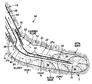
Referring to FIG. 1, a wellbore 10 is shown having a vertically-deviated upper
segment
12 and a substantially horizontal lower segment 14. A casing string 16 lines
the upper segment
12 while the lower segment 14 is shown as an open hole, although casing 16
could be placed in
the lower segment 14 as well. To the extent casing 16 covers any producing
formations, casing
16 must be perforated to provide fluid communication between the formations
and wellbore 10,
as is well known to those of ordinary skill in the art.
A packer assembly (hereafter "packer") 18 is set generally near the lower end
of upper
wellbore segment 12. The packer 18 engages and seals against the casing 16, as
is also well
8
CA 02492741 2005-01-18
known in the art. The packer 18 has an extension 20 to which other lower
completion equipment
such as tubular wellbore screen 22 can attach. The screen 22 is preferably
disposed adjacent a
producing formation F.
A service tool 24, in the form of a conduit commonly known as a wash pipe, is
sealably
positioned in the wellbore 10 by passing through and engaging the central
elastomeric portion of
the packer 18. The wash pipe 24 extends to or near the lower end or "toe" T of
the lower
wellbore segment 14. With the wash pipe 24 in place, an upper wellbore annulus
26 is formed
above the packer 18 between the wall of wellbore 10 and the wall of the wash
pipe 24, and an
isolated lower wellbore annulus 23 is formed between the wall of the wash pipe
24 and the wall
of wellbore 10. The screen 22 divides the isolated lower annulus 23 into inner
lower annulus 27a
and an outer lower annulus 27b.
FIG. 1 further illustrates a schematic representation of a crossover 28 just
below the point
where the wash pipe 24 passes through the packer 18. The crossover 28 allows
fluids pumped
through the wash pipe 24 to emerge into the outer lower annulus 27b below the
packer 18. Fluids
entering the wash pipe 24 below the packer 18, such as through the open end 25
of the wash pipe
24 at or near the toe T of the wellbore 10, are conveyed upwardly through the
wash pipe. Upon
reaching the crossover 28, the returning fluids are conveyed through or past
the packer 18 and
into the upper annulus 26, through which the return fluids are ultimately
conveyed to the surface.
At least one valve member, such as a diverter valve 30, is mounted to the wash
pipe 24
below the packer 18. In the embodiment of FIG. 1, three diverter valves 30 are
carried at discrete
points A, B, C for selectively admitting fluid from the isolated lower annulus
23 into the wash
pipe 24 at the discrete locations. FIG. 2 illustrates a simplified schematic
representation of the
array 29 of diverter valves 30 as positioned by the wash pipe 24 (not shown in
FIG. 2)
9
CA 02492741 2005-01-18
independently of, but in wired communication with, the pressure-sensitive
device 48 (described
below). Each diverter valve 30 preferably forms an integral part of the wall
of the wash pipe 24,
but other embodiments such as valve members being mounted to the wash pipe 24
such that the
valve covers and seals openings (not shown) in the wash pipe are within the
scope of this
invention. The valves 30 may be (or may comprise) check valves, meaning they
will allow fluid
to flow in one direction only when in an open state, as is described further
below with respect to
FIGS. 6 and 7A-7B.
FIG. 3B shows schematically the components of one embodiment of a diverter
valve 30.
Each of the valves 30 includes a valve body carried within and/or forming part
of the wash pipe
24. The valve body includes an upper housing 32 attached to a lower housing
34. Although FIG.
3B shows the valve housings 32, 34 attached by a threaded connection, other
connectors or
connection-types may be used. Additionally, the valves 30 may also employ a
single-piece body,
rather than the two-piece body shown.
The valve body is equipped with at least one first port 50 formed in the upper
housing 32
for admitting fluid from the isolated lower annulus 23 into the wash pipe 24.
A piston 36 is
sealingly and slidably disposed in a chamber 38 defined by the valve body
housings 32, 34. The
piston 36 is movable from a position closing the first port 50 (as shown in
FIG. 3B) to a position
opening the first port upon actuation of the piston (described below). The
piston 36 is equipped
with an upper end 49 and a lower end 51, with the surface area of upper end 49
being less than
the surface area of lower end 51 so that ambient wellbore fluid pressure urges
the piston 36 to the
closed position when the wash pipe is initially positioned in the wellbore 10.
The piston has a head or flanged portion 40 disposed for slidable movement
within an
enlarged portion of the valve body chamber 38. The flanged piston portion 40
divides the
CA 02492741 2005-01-18
enlarged chamber portion into first (upper) and second (lower) enlarged
chambers 42, 44. The
piston flange 40 carries a seal 46 that seals against a portion of the lower
housing 34 that defines
the enlarged portion of the chamber 38, and thereby isolates the first
enlarged chamber 42 from
the second enlarged chamber 44. The piston 36 also carries a seal 47 that
seals against a lower
portion of lower housing 34, thereby sealing the lower end of the second (or
lower) enlarged
chamber 44.
The upper valve body housing 32 is further equipped with a second port 55 for
admitting
fluid pressure from the isolated lower annulus 23 to the first enlarged
chamber 42 via an internal
conduit 57 of the second port 55. In this manner, wellbore fluid pressure may
be applied to urge
the piston to the position opening the first port 50 (not shown in FIG. 3B,
but see FIG. 8B). The
upper valve housing 32 further includes a flow control device, such as a
solenoid valve 91,
powered by a battery 91 b and moveable between positions opening and closing
the conduit 57 of
the second port 55 upon actuation of the solenoid valve 91 via a conductor 77
by a pressure-
sensitive device, which will now be described.
A pressure-sensitive device 48, shown in FIGS. 1, 2 and 3A, is carried by the
wash pipe
24 independently of the valves 30 for sensing the pressure within the isolated
lower wellbore
annulus 23 while gravel packing. The pressure-sensitive device 48 can include,
but is not limited
to, a rupture disk or a pressure pulse telemetry device in which an amplitude
or frequency
modulated pressure pulse triggers the device. A particular embodiment of the
pressure-sensitive
device 48 includes a battery 81, a pressure transducer 83, a processor 85, and
a
capacitor/transmitter 87. The battery 81 provides power for the processor 85
and the
capacitor/transmitter 87. The pressure-sensitive device 48 interacts with a
movable chamber
divider 89, exposed to wellbore fluid pressure on its upper side, and a
solenoid valve 91 of each
11
CA 02492741 2005-01-18
valve 30. It will be appreciated by those skilled in the art that the solenoid
valve 91 can be
replaced by other flow control devices, including an explosive element.
Hydraulic communication between the pressure transducer 83 and the ambient
wellbore
fluid is achieved through communication port 79 of the pressure-sensitive
device 48. The internal
space around the pressure transducer and the communication port may be filled
with a non-
conductive hydraulic fluid. The port 79 may contain a filter to provide both a
flow restriction
against hydraulic fluid loss during deployment, and also act as a filter once
wellbore fluid is in
contact with the port opening.
The pressure transducer 83 converts a pressure signal (i.e., a sensed wellbore
pressure) to
an electrical signal and provides that electrical signal to the processor 85.
The processor 85
analyzes the electrical signal to determine whether a threshold pressure
condition exists in the
isolated lower annulus 23, and, if so, commands the capacitor/transmitter 87
to send an actuation
signal to the solenoid valve 91 (shown in FIG. 3B). When solenoid valve 91 is
actuated to open
the conduit 57 of the valve port 55, the lower side of chamber divider 89 is
exposed to the
reduced pressure (e.g., atmospheric) of first enlarged valve chamber 42. The
resulting pressure
differential across the chamber divider 89 moves the chamber divider towards
the conduit 57,
causing hydraulic fluid within the conduit 57 and the chamber 42 to bear on
the piston flanged
portion 40 and displace the piston 36 to an open position (see FIG. 8B). This
sequence of events,
from pressure sensing to piston displacement, is very rapid (e.g., within
seconds or fractions of a
second) and occurs on a real-time basis while gravel packing operations are
being conducted.
With reference again to FIGS. 1 and 2A-2B, the pressure-sensitive device 48 is
preferably carried by the wash pipe 24 such that the pressure-sensitive device
is positioned
adjacent the wellbore packer assembly 18. Accordingly, the device 48 is
conveniently placed at
12
CA 02492741 2011-06-30
78543-170
or near a location of high absolute pressure within the isolated lower annulus
23, and more
particularly within the inner lower annulus 27a. The pressure-sensitive device
48 actuates one or
more diverter valves 30 by transmitting one or more actuation signals from the
capacitor/transmitter 87. The one or more actuation signals may be transmitted
wirelessly, e.g.,
using a transmitter coil (not shown), such as a radio frequency ("RF")
antenna, other
electromagnetic ("EM") transmitter means, inductive coupling, or by a
conductor 77 extending
between the controller and the valves. The conductor 77 may include one or
more insulated
wires, optical fibers, etc., carried along the conduit that defines wash pipe
24, in a similar manner
to that employed in the art of wired drill pipe (see, e.g., U.S. Patent No.
6,641,434).
As mentioned above, the solenoid valve 91 of one of more of the valves 30 is
actuated
when the pressure sensed by the pressure-sensitive device 48 corresponds to
one or more
threshold pressure conditions. The device 48 may, e.g., be responsive to an
absolute pressure of
the isolated lower annulus 23 (or, more precisely, inner lower annulus 27a),
or a pressure
differential across the wall of the wash pipe 24. Pressure condition criteria
to trigger a response
can include proximity to a target absolute pressure - particularly local
fracture pressure, the
slope or rate of change of the sensed pressure with respect to time, observed
trends in a pressure
profile produced at the surface, or a combination of criteria being
simultaneously met. More
particular explanation of a pressure pulse telemetry device can be found in
U.S. Patent No.
4,796,699.
When the pressure-sensitive member 48 commands solenoid valve 91 to its "open"
state,
the solenoid valve allows fluid pressure communication between the inner lower
annulus 27a and
the enlarged first chamber 42 of one or more valves 30. Such fluid pressure
communication
energizes the valve chamber 42 to induce sliding movement of the valve piston
36. The first port
13
CA 02492741 2005-01-18
50 can therefore provide fluid communication between the inner lower annulus
27a and the
interior of the wash pipe 24. The piston 36 carries seals 52, 53, shown in
FIG. 3B, that seal
against the portion of the upper housing 32 that define chamber 38 to prevent
or allow such fluid
communication, depending on the position of the piston 36. The seal 53 also
serves to seal the
upper end of the enlarged first (upper) chamber 42.
Additional safeguards, such as a closure mechanism for selectively closing
each of the
first valve ports 50, may be employed. FIG. 5 shows schematically a valve
embodiment 30' that
employs a plurality of radially-distributed first ports 50. With reference to
FIG. 6, each of the
first ports 50 is equipped with a check valve in the form of a flapper valve
31 to ensure fluid
flows through each first port 50 in one direction: from the isolated lower
annulus 23 to the wash
pipe 24. The flapper valve 31 includes a plurality of pivotally mounted plates
31p that are
adapted for rotation from an open position (shown in FIG. 6) to a closed
position (not shown)
should the fluid pressure within the wash pipe 24 exceed the ambient wellbore
fluid pressure
within the isolated lower annulus 23 (in particular, within the inner lower
annulus 27a) when the
piston 36 is moved to an open position.
FIGS. 7A-7C shows a diverter valve embodiment 30" employing a flapper valve
31'
having a single pivotally-mounted plate 31p' for closing a first port 50'. The
plate 31p'
cooperates with a cover plate 33, equipped with a central opening 33a (see
FIG. 7B), to prevent
fluid within the wash pipe 24 from exiting through the first port 50'.
It will be appreciated that the above-described diverter valve embodiments 30'
and 30"
have utility independent of the wash pipe 24 described herein. Thus, e.g., an
open-ended conduit
employing an array of such diverter valves would allow an operator to "spot"
(i.e., accurately
place) fluids such as Schlumberger's MudSOLVETM treatment fluid directly after
gravel packing
14
CA 02492741 2005-01-18
is achieved. The fluids could therefore be spotted through the open end of the
conduit without
risk of inadvertent release through one of the diverter valves, because fluid
pressure applied in
the conduit would force such diverter valves to closed positions, ensuring
that the fluids exited
the open end of the conduit.
FIGS. 8A-8C are sequential, cross-sectional representations of the inventive
valve
employing a further embodiment of a closure mechanism in accordance with the
present
invention. In the first position depicted by FIG. 8A, the piston 36 is
initially urged to a closed
position by the ambient wellbore pressure inducing a greater force against
lower piston end area
51 than upper piston end area 49. In the second position depicted by FIG. 8B,
the piston 36 has
been urged to an open position under actuation of the solenoid valve 91 by the
pressure-sensitive
device 48 (not shown in FIGS. 8A-8C). In this embodiment, the second enlarged
chamber 44 of
the valve body includes a bum chamber 44a housing a propellant 44p and an
igniter system 44i
for generating pressure for urging the piston 36 from the position opening the
first port 50 (see
FIG. 8B) to the position closing the first port, as depicted by FIG. 8C. The
igniter 44i is actuated
by a signal from the capacitor/transmitter 87 of the pressure-sensitive device
48 via a conductor
75. The actuation signal is transmitted upon the sensing of a particular mud-
pulse signal
(generated, e.g., via conventional mud-pulse telemetry means) by the pressure
transducer 83 of
the pressure sensitive device 48. The propellant may include, e.g., a solid
fuel pack having
materials that generate pressure as they ignite and burn. The second enlarged
chamber 44 further
includes a pair of movable chamber dividers 44b, 44c that isolate a volume 45
of hydraulic fluid
therebetween so as to enable the pressure generated in the burn chamber 44a to
be transferred to
the piston flange 40 while retaining the combustion products within the burn
chamber. When the
piston 36 is thereby returned to the closed position, fluid pumped downwardly
though the wash
CA 02492741 2005-01-18
pipe 24 is forced to exit the open end 25 thereof (assuming the crossover 28
is closed or
removed).
A gravel packing operation utilizing the present invention will now be
described. The
packing operation begins by lacing lower completion equipment including the
packer 18, packer
extension 20, and screen 22 within the wellbore 10. A wash pipe 24 is run into
the wellbore 10
through the packer 18 such that a crossover 28, diverter valves 30, and the
open lower end 25 of
the wash pipe 24 are properly positioned. Because the chamber 38 of each valve
30 is initially set
at atmospheric pressure, and because the surface area of the lower end 51 of
each valve piston 36
is greater than the surface area of the upper end 49 of the piston 36, each
piston 36 is
hydraulically biased to its upward position as the wash pipe 24 is lowered
into position within
the wellbore 10. This ensures that port 50 remains closed until purposely
opened (or,
equivalently, covering and sealing holes in the wash pipe 24).
A gravel slurry is pumped into the wash pipe 24 and ejected via the crossover
28 into the
isolated outer lower annulus 27b. The gravel slurry may be of various
concentrations of
particulates and the carrier fluid can be of various viscosities. In
substantially horizontal
wellbores, and particularly with a low-viscosity carrier fluid such as water,
the placement or
deposition of gravel generally occurs in two stages. During the initial stage,
known as the "alpha
wave", the gravel precipitates as it travels downwardly to form a continuous
succession of dunes
54 (see FIG. 1). Depending on factors such as slurry velocity, slurry
viscosity, sand
concentration, and the volume of the isolated lower annulus 23, each dune 54
will grow in height
until the fluid velocity passing over the top of dune 54 is sufficient to
erode the gravel and
deposit it on the downstream side of dune 54. The process of building up a
dune 54 to a
16
CA 02492741 2005-01-18
sustainable height and deposition on the downstream dune side to initiate the
build-up of each
successive dune 54 is repeated as the alpha wave progresses to the toe T of
wellbore 10.
As the alpha wave travels to the toe T and the gravel settles out, the carrier
fluid
preferably travels in outer lower annulus 27b or passes through screen 22 and
enters inner lower
annulus 27a and continues to the toe where it is picked up by wash pipe 24 via
open end 25, and
then conveyed to the surface. A proper layer of "filter cake," or "mud cake"
(a relatively thin
layer of drilling fluid material lining wellbore 10) helps prevent excess leak-
off to the formation.
When the alpha wave reaches the toe T of the wellbore 10, the gravel begins to
backfill
the portion of the lower annulus 23 left unfilled by the alpha wave. This is
the second stage of
the gravel pack and is referred to as the "beta wave." As the beta wave
progresses toward the
heel H (see FIG. 1) of the wellbore 10 and gravel is deposited, the carrier
fluid passes through
screen 22 and enters inner lower annulus 27a. So long as the diverter valves
30 remain closed,
the carrier fluid must make its way to the open end 25 near the toe T to be
returned to the
surface. As the beta wave gets farther and farther from the toe T, the carrier
fluid entering the
inner lower annulus 27a must travel farther and farther to reach the open end
25 of the wash pipe
24. The flowpath to the toe through the outer lower annulus 27b is effectively
blocked because
of the deposited gravel. As is common in fluid flow, the pressure in wellbore
10 tends to increase
due to the increased resistance resulting from the longer and more restricted
flowpath.
FIG. 4A shows a typical plot of expected pressure in wellbore 10 with a prior
art wash
pipe having no diverter valves therein. For reference, FIG. 4A also shows the
limiting pressure or
fracture pressure of the formation, above which damage to the formation may
occur. Pumping
operations are generally halted just below fracture pressure. This early
termination of pumping
results in an incomplete gravel pack.
17
CA 02492741 2005-01-18
FIG. 4B shows a typical pressure profile expected with the use of diverter
valves 30 and a
pressure-sensitive device 48 in accordance with the present invention. The
valves 30 are
strategically placed along the lower length of the wash pipe 24. Proper
placement of the valves
30 and the determination of threshold pressure conditions for pressure-
sensitive device 48 vary
according to the pressure environment of a particular wellbore 10. This
pressure environment can
be modeled or simulated using known computational techniques for estimating
wellbore
pressure. Using such techniques allows engineering estimates for optimal
placement of valves 30
and selection of an appropriate pressure-sensitive device 48.
FIGS. 1, 2, and 4B show the locations of three diverter valves 30 and the
pressure plot
corresponding to their use with a pressure-sensitive device 48 designed for
responding to the
respective pressure threshold conditions associated with the three valves. The
respective valve
locations are designated by points A, B, and C depicted on FIGS. 1, 2, and 4B.
In operation, after
the alpha wave reaches the toe T and the beta wave reaches valve point A, the
wellbore pressure
- which has been sensed by the pressure-sensitive device 48 throughout gravel
packing - is
elevated to a magnitude just sufficient to correspond to a threshold pressure
condition PThresh of
the pressure-sensitive device 48. This triggers the transmission of an
actuation signal from the
pressure-sensitive device 48 to the valve 30 positioned at point A, thereby
exposing the enlarged
first (upper) chamber 42 of that valve 30 to the pressure in inner lower
annulus 27a. This
pressure exceeds the atmospheric pressure in the second (lower) enlarged
chamber 44, causing
the piston 36 of that valve to move downwardly, exposing the first port 50 to
the inner lower
annulus 27a. With the first port 50 in its "open" state, the carrier fluid no
longer must travel to
the open end 25 of the wash pipe 24 to return to the surface. Instead, the
carrier fluid enters the
18
CA 02492741 2005-01-18
wash pipe 24 through the first port 50 at valve point A. This allows the
wellbore pressure to
drop, as shown in the vertical, linear portion of the pressure profile
adjacent point A in FIG. 4B.
As the beta wave continues up wellbore 10 toward the heel H, the annulus
pressure will
increase as the flow path again lengthens. However, upon passing point B, the
pressure will
again be sufficient to correspond to the threshold pressure condition PThresh
of the pressure-
sensitive device 48. As before, this results in actuation of the diverter
valve 30 at point B by the
pressure-sensitive device. That creates a flow path from inner lower annulus
27a into the wash
pipe 24 at point B, thus relieving the wellbore pressure again. This process
is repeated for each
additional diverter valve 30, as illustrated again at point C.
FIG. 4B also shows the relative time a standard gravel pack (without diverter
valves 30 or
pressure-sensitive device 48) will be allowed to run until halted at the
pressure P, anticipated at
point C, just below the fracture pressure. It also shows the additional
relative packing time
permitted when diverter valves 30 are used according to the present invention.
The term
"relative" time is used to indicate the controlling factor is really wellbore
versus fracture pressure
since time van be extended or shortened by varying other parameters. However,
by controlling
pressure, extended relative pumping times can be gained. Additional time is
gained because the
open diverter valves 30 reduce the resistance to the return of carrier fluids
to the surface due to
shortened flow paths. If diverter valves 30 are properly chosen, the gravel
pack operation can be
run until the screens are completely covered, while never exceeding the
fracture pressure.
Although the diverter valves 30 are described as being employed with a
pressure-sensitive device
48 having a plurality of respective threshold (actuating) pressure conditions,
it will be
appreciated by those having ordinary skill in the art that the pressure-
sensitive device may be
19
CA 02492741 2005-01-18
designed to open all of the diverter valves carried by the wash pipe upon the
presence of a single
threshold pressure condition within the isolated lower wellbore annulus 23.
It will be further appreciated that the rate of fluid return upwardly through
the wash pipe
24 can be regulated using a choke, as is well known in the art. Such use of a
choke gives an
operator an additional means of control over the actuation of the diverter
valve(s) 30 by the
pressure-sensitive device 48 by allowing the operator to selectively increase
the wellbore
pressure to the actuation level, should the operator so choose.
It will be still further appreciated that the present invention admits to a
number of
advantages, including but not limited to: wellbore pressure control without
the need for
monitoring/locating the beta wave; tolerance to unexpected events such as high
leak-off rate to
the formation and/or drop in proppant concentration; freedom of diverter valve
locations;
enhanced reliability by interconnection of diverter valves; adaptive to
multiple pressure-sensing
locations (e.g., in annulus above packer); easily retrievable; simplified
control/actuation logic
with reduced risk of false actuation; and not dependent on the use of a
polished bore receptacle
(PBR) in the screen.
Although only a few exemplary embodiments of this invention have been
described in
detail above, those skilled in the art will readily appreciate that many
modifications are possible
in the exemplary embodiments without materially departing from the novel
teachings and
advantages of this invention. Accordingly, all such modifications are intended
to be included
within the scope of this invention as defined in the following claims.
In the claims, means-plus-function clauses are intended to cover the
structures described
herein as performing the recited function and not only structural equivalents,
but also equivalent
structures. Thus, although a nail and a screw may not be structural
equivalents in that a nail
CA 02492741 2011-06-30
78543-170
employs a cylindrical surface to secure wooden parts together, whereas a screw
employs a
helical surface, in the environment of fastening wooden parts, a nail and a
screw may be
equivalent structures.
The term "comprising" within the claims is intended to mean "including at
least" such
that the recited listing of elements in a claim are an open set or group.
Similarly, the terms
"containing," having," and "including" are all intended to mean an open set or
group of
elements. "A," "an" and other singular terms are intended to include the
plural forms thereof
unless specifically excluded.
21