Note: Descriptions are shown in the official language in which they were submitted.
CA 02492991 2005-O1-19
WO 2004/009337 PCT/US2003/022825
SEGMENTED TIRE MOLD TO REDUCE FLASH
BACKGROUND OF THE INVENTION
1. TECHNICAL FIELD
The invention relates to molds for vulcanizing green tires. More
specifically, the invention relates to an improved mold wherein the mold
parting
lines between the tread mold sections and sidewall mold plates reduce flash to
provide a more pleasing sidewall on the molded tire.
2. BACKGROUND INFORMATION
Various types of vulcanizing molds have been developed, many of which
include annular arrays of tread mold segments which are movable with respect
to each other, for enclosing a green tire to be subsequently vulcanized
therein.
These mold segments are movable in an outward direction from upper and
lower sidewall mold plates in order to load the green tire into the mold and
subsequently remove the molded tire from the mold. The mold segments, when
in abutting contact with the sidewall mold plates, form mold part lines which
are
susceptible to receiving small amounts of the elastomeric material or rubber
from the green tire as the green tire rubber is forced outwardly under
pressure
against the mold surfaces and subsequently into the mold part lines. This
rubber results in flash being formed on the tire at the mold part lines, which
depending upon its location and amount, can result in a less aesthetically
pleasing finished tire. Although this flash does not effect the performance of
the
tire, it does effect the appearance of the finished tire, especially when it
appears
on the outside sidewall region of the tire. In order to remove this excess
flash,
various grinding operations are used which increase the cost of production.
This aesthetic aspect of newly vulcanized tires is important for all tires
including tires having aggressive sidewall patterns, such as for vehicles
which
have both on-road and off road usage. The appearance of the tire sidewalls is
important to many vehicle owners and the presence of flash thereon detracts
from the appearance of the tire and vehicle.
1
CA 02492991 2005-O1-19
WO 2004/009337 PCT/US2003/022825
In certain tire constructions, a strip of nylon, such as a nylon cap ply
which extends circumferentially throughout the tire and axially between the
sidewall areas, or nylon cap layers which are located at the shoulder regions
of
the tires, are added as an additional reinforcement adjacent to the
reinforcement belt package of the tire. These nylon strips make the belt
package more rigid and it has been found that this increased stiffness reduces
the flexure of the belt package when being molded in the crown portion of a
tire
which results in an increase in the amount of flash generated during the
vulcanization of the tire. These nylon cap plies and cap layers are being
incorporated into many tires including those having a more aggressive sidewall
patterns, and the presence of flash in these tires becomes an increasing
problem.
Although various molds can be developed to reduce excessive flash in
the sidewall areas when a nylon strip is incorporated into the belt package,
it
would increase considerably the cost of the vulcanization molds and require
considerable retrofit to existing segmented molds.
Therefore, the need exists for an improved segmented mold for molding
green tires, especially when they contain a nylon cap ply or nylon cap layer,
to
reduce flash in the sidewall areas of the tire without requiring excessive
modification to existing molds.
BRIEF SUMMARY OF THE INVENTION
One aspect of the invention is to provide a tire vulcanization mold of the
type having an annular array of tread mold segments which are brought into
abutting engagement with spaced sidewall mold plates, wherein the parting
lines formed between the mold segments and plates reduce the amount of flash
generated therein, especially when the green tire has a nylon cap ply or nylon
cap layer, by locating the mold line in close alignment with the nylon strip
or
strips in the crown portion of the tire.
Another aspect of the invention is to locate the mold part lines between
the tread mold segments and sidewall mold plates at a distance not greater
2
CA 02492991 2005-O1-19
WO 2004/009337 PCT/US2003/022825
than '/Z inch inwardly from the inner circumferential surface of the tread
mold
segment which forms the skid surFace on the molded tire.
A further aspect of the invention is to enable the tire, which is molded
within the mold, to have various combinations of nylon strips, such as a nylon
cap ply which extends axially between the sidewall of the tire, alone or in
combination with one or more nylon cap layers located in the shoulder regions
of the green tire.
A further feature of the invention is to form the mold part fines closely
adjacent to the shoulder region of the finished tire to make any resulting
flash
less obtrusive than if the flash is formed lower in the sidewall of the tire,
especially tires having a more aggressive tread pattern forming the sidewall
area.
The foregoing advantages, construction and operation of the present
invention will become more readily apparent from the following description and
accompanying drawings.
BRIEF DESCRIPTION OF THE DRAWINGS
Fig. 1 is a diagrammatic side elevational view with portions broken away
and in section, of one type of tire press containing the improved mold of the
present invention;
Fig. 2 is an enlarged diagrammatic sectional view of the tread mold
segments and sidewall mold plates removed from the press of Fig. 1;
Fig. 3_ is an enlarged fragmentary sectional view of the tire building mold
mounted within the tire molding press of Fig. 1;
Fig. 4 is a further enlarged fragmentary sectional view of a portion of Fig.
3;
Fig. 5 is a greatly enlarged fragmentary sections( view of the encircled
portion of Fig. 4 showing a single nylon cap ply located between the body ply
carcass and tread of the tire;
Fig. 6 is a view similar to Fig. 5 showing the addition of a nylon cap layer
above the nylon cap ply in the shoulder region of the tire;
3
CA 02492991 2005-O1-19
WO 2004/009337 PCT/US2003/022825
Fig. 7 is a fragmentary view similar to Figs. 5 and 6 showing two nylon
cap layers above the nylon cap ply in the shoulder region of the tire;
Fig. 8 is a fragmentary view similar to Figs. 5-7 showing a nylon cap
layer in the shoulder region of the tire without a nylon cap ply;
Fig. 9 is a fragmentary sectional view similar to Figs. 5-8 showing two
nylon cap plies with a single nylon cap layer; and
Fig. 10 is a fragmentary perspective view of a pneumatic tire produced
by the mold of the present invention containing the nylon reinforcing strip.
Similar numerals refer to similar parts throughout the drawings.
DETAILED DESCRIPTION OF THE INVENTION
One type of press in which the improved segmented mold is mounted, is
indicated generally at 1, and is shown diagrammatically in Fig. 1. Press 1 is
similar in some respects to the press shown in U.S. Patent No. 5,866,170, the
contents of which are incorporated herein by reference. Press 1 includes upper
and lower platens 2 and 3 respectively, with an outer ring 9 being attached to
platen 2. Outer ring 9 has an inner tapered surface 12 which is complementary
to and in sliding engagement with tapered surfaces 11 of a plurality of inner
slide blocks 8 which form a mold closure ring. Lower platen 3 is supported on
a
base 6 and a hydraulic or pneumatic pressure device 7 raises and lowers a top
mold plate 10. Gear 39 raises and lowers top platen 2 and outer ring 9 through
a linkage 39A. The improved mold, indicated generally at 4, includes an
annular array of tread mold sections 15 and annular sidewall mold plates 16
and 17. The particular construction and operation of press 1 as shown in Fig.
1
can be varied without effecting the concept of the invention. The drawings
illustrate one type of press and segmented mold having the radially outwardly
movable mold segments 15 and sidewall plate 16 and 17 which provide the
reduced flash in the sidewall regions of a vulcanized tire.
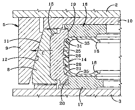
The main and distinguishing feature of the invention is shown particularly
in Figs. 2-4, wherein tread mold segments 15 mate with sidewall mold plates 16
and 17 in an abutting relationship and form a pair of annular mold part lines
19
and 20 therebetween, which part tines are very high in the sidewail regions of
4
CA 02492991 2005-O1-19
WO 2004/009337 PCT/US2003/022825
the tire closely adjacent the shoulder area and not lower down in the sidewall
region as in prior molds and tires. As in most vulcanization molds, the part
lines
formed between the various mold segments and sidewali plates will create a
flash line 22 on the sidewalls 23 of a usual pneumatic vulcanized tire 28 such
as shown in Fig. 10. However, one of the main features of the invention is the
elimination or reduction of flash that will appear along line 22 on tire
sidewalls
23 in vulcanized tire 28, and the location of this flash line high up on the
sidewall and closely adjacent the shoulder region of the tire.
The operation of the particular mold 1, which is shown in the drawings, is
best illustrated in Fig. 1 and is the same for similar segmented molds not
having
the unique parting line locations of the present invention. Gear 39 and
linkage
39A, or a pneumatic or hydraulic device (not shown), raises platen 2 and
connected ring 9. Simultaneously therewith, pressure device 7 extends mold
plate 10 and top sidewall mold plate 16 connected thereto, which releases the
clamping engagement between ring 9, slide blocks 8 and mold segments 15. A
vulcanized tire can then be removed from the mold and a green tire 14 placed
therein. After a green tire is loaded into the press, a generally reverse
procedure clamps the mold components 15, 16 and 17 about green tire 14.
This is a typical sequence of operation of a press in which the mold of the
present invention will be incorporated. However, other types of molds and
operating sequences can be utilized to achieve the same results.
As shown in Fig. 2, tread mold segments 15 include a circumferentially
extending slightly curved smooth inner surface 25 which has a plurality of
inwardly extending projections 26. Surface 25 will form skid surface 27 on
vulcanized tire 28 with projections 26 forming the various tire lug elements
30
as shown in Fig. 10. Tread mold segments 15 may also have several
projections 31 in the outer axial ends or shoulder forming regions, as shown
in
Fig. 2, which are located closely adjacent part lines 19 and 20 to assist in
forming part of the shoulder lug elements 33 of tire 28. The term skid surface
refers to the outer surface area of the finished tread from which the tread
lugs
30 extend, or referred to as the bottom surfaces of the intervening tire lug
5
CA 02492991 2005-O1-19
WO 2004/009337 PCT/US2003/022825
grooves. This surface matches and is formed by inner surface 25 of tread mold
segments 15.
Sidewatl plates 16 and 17 will also be provided with various projections
35 which extend axially inwardly from annular cavity surfaces 24 to form a
variety of sidewall projections 36 as shown on finished tire 28 in Fig. 10.
Fig, 2
diagrammatically represents a section through sidewall plates 16 and 17, which
when joined in an abutting relationship with a tread mold segment 15 in a
closed position as shown in Fig. 3, molds finished tire 28 therein.
In accordance with another feature of the invention as shown particularly
in Fig. 2, mold part lines 19 and 20 will be located a distance "D" inwardly
from
the inner tread mold circumferential surface 25, which for most tire sizes
will be
'/2 inch or less. This distance "D" is measured from an imaginary line 29
extending axially between the start of the mold parting lines 19 and 20. This
distance will insure that the mold part lines 19 and 20 will be in general
axial
alignment with a nylon reinforcing strip, whether it be a nylon cap ply or
nylon
cap layer, when located within crown portion,38 of tire 28, which nylon strips
are
shown in Figs. 5-9 and described further below. Imaginary line 29 is viewed in
cross section, which in three dimension will be an imaginary cylinder
extending
coaxial with and inside of circumferential mold surface 25. The term axial is
in
relation to rotational axis 32 of green tire 14 and of mold 1 as shown in Fig.
9.
Thus imaginary line 29 is referred to as axially extending which terminates
adjacent the axial ends of mold 1 and of crown portion 38 of green tire 14.
As indicated above, the improved segmented tire mold of the present
invention is successful in reducing flash at the mold part lines which appear
in
the upper sidewalls of the tire, and in particular, when a nylon reinforcing
strip is
incorporated into the crown portion of the tire between the belt package and
tread. Heretofore, this nylon strip or strips stiffen the belt package so it
will not
flex enough during molding of the tire, resulting in excessive flash being
formed
at part lines 19 and 20, and subsequently appearing on the sidewalls of the
molded tire. These nylon strips are desirable for certain tires since they
enhance the high speed capability of the tire and provide cut resistance,
particularly to load carrying steel belted tires which are used for both on-
road
6
CA 02492991 2005-O1-19
WO 2004/009337 PCT/US2003/022825
and off-road. However, reduced flash is important to the purchaser of all
types
of tires, including those tires having a more aggressive tread pattern in the
sidewall area.
Fig. 5 shows an enlarged fragmentary sectional view of one shoulder
region of green tire 14 being molded in mold 1 having the nylon reinforcing
strip
therein. A body ply carcass indicated generally at 40 is shown with four body
plies 41, 42, 43, and 44. Ply 41 is the innerliner and is formed of an air
impervious elastomeric material, with plies 42, 43 and 44 being cord
reinforced
elastomeric strips. In addition to body ply carcass 40, a belt package 45 is
mounted in the crown portion of the tire between carcass 40 and the tread.
One example of belt package 45 includes a pair of steel belts 46 and 47 which
are formed by a plurality of steel cords calendered in a thin layer of rubber.
A
wedge of rubber 48 preferably is located between steel belts 46 and 47
adjacent shoulder region 50.
In accordance with one of the features of the invention, a nylon cap ply
52 is located between belt package 45 and a pair of rubber cap strips 54 and
55, wherein portions of outermost rubber cap strip 54 form skid surface 27 of
the tire tread. Nylon, cap ply 52 preferably terminates in a pair of stepped
axial
ends 56 which are located inwardly from the curved ends 57 and 58 of rubber
cap strips 54 and 55 respectively.
In accordance with one of the important aspects of the invention, mold
line 19 located between tread segments 15 and sidewall plate 16 is in general
axial alignment with nylon cap ply 52 as illustrated by an axially extending
dot
dash line 60 in Fig. 5. However, part line 19 can vary within a relatively
small
distance represented by arrow A, having its lower limit at the interface
between
body ply carcass 40 and belt package 45, represented by dot dash line 69, and
its other limit at skid surface 27, represented by dot dash line 70. Distance
A in
most tire constructions utilizing a nylon strip will be no greater than '/z
inch.
Thus part line 19 is located between the body ply carcass 40 of the tire to be
vulcanized therein, and inner circumferential tread segment surface 25 which
forms skid surface 27 on the vulcanized tire. This results in flash line 22
appearing very high up in the fire sidewall closely adjacent to the shoulder
7
CA 02492991 2005-O1-19
WO 2004/009337 PCT/US2003/022825
region as shown in Fig. 10 in contrast to prior art tires where the flash line
is
lower in the sidewall area.
Fig. 6 shows a modified tire construction to be molded within mold 1
wherein a nylon cap layer 62 is mounted over each axial end of nylon cap ply
52 adjacent each shoulder region 50. The remaining body ply carcass, steel
belts and rubber wedge are the same in the tire of Fig. 6 as is the tire shown
in
Fig. 5. . Again, mold part line 19 is within the same critical region as that
described above and designated by Arrow A in Fig. 5.
Part lines 19 and 20 can extend at various angles, as shown by dot
dash lines 19A and 19B without effecting the invention so long as i:he start
of
the segment part line, which is in contact with the elastomeric material,
designated by 61 in the drawings, is within the critical area designated by
arrow
A in Fig. 5. It is this location 61 which starts the part line which
determines the
location of flash line 22 on the molded tire and that the angle of the mold
part
line as it extends form reference 61 does not effect the location of flash
line 22
on tire 28.
Fig. 7 shows a further modified tire construction in which two nylon cap
layers 62 and 63 are mounted over the axial ends of nylon cap ply 52. Again,
mold part line 19 will be within the same critical area designated by arrow A.
, 'Fig. 8 shows another modified tire construction in which only a single
nylon cap layer 62 is located at each axial end of the tread at the shoulder
regions without any nylon cap ply 52 being utilized.
Fig. 9 shows a further embodiment in which two nylon cap plies 52 and
64 extend axially across the tire tread and throughout the crown portion
between the shoulder regions and terminating in stepped ends 56 and 65
respectively, with a single nylon cap layer 62 being mounted thereon at each
shoulder region, which also terminates in a stepped end 67.
Again, irrespective of the number and arrangements of nylon strips,
whether it be one or more nylon cap plies or cap layers, mold part lines 19
and
20, and in particular, starting locations 61 thereof, will be in general axial
alignment with the nylon strips and as discussed above, will be within the
critical
distance defined by inner mold surtace 25 which defines skid surface 27 of the
8
CA 02492991 2005-O1-19
WO 2004/009337 PCT/US2003/022825
molded tire, and the interface between body ply carcass 40 and belt package
45, which is shown in the drawings and designated by distance A, which as
indicated previously, is no greater than % inch for most tire sizes.
Accordingly, the improved tire mold and combination tire mold and
pneumatic tire having the nylon strips located in the crown portion of the
tire
between the belt package and skid surface, provides a mold structure and
mold-tire combination which enables a pneumatic radial tire to be produced
with
a reduced amount of flash in the sidewalls of the tire, designated by flash
line
22 in Fig. 10, by forming the mold part lines in an area very high in the tire
sidewall areas closely adjacent to the shoulder regions of the tire whereas in
prior art structures, the mold flash line was lower down the sidewall of the
tire
and not located in the critical area defined above and shown in the drawing.
As
easily seen in Fig. 10, any resulting flash designated by line 22 will be less
obtrusive to a casual observer than if located lower in the sidewall region.
The Location and reduced flash line 22 is important in both of the
sidewalk of the tire so that the outside sidewall when mounted on a vehicle
provides an attractive appearance. Also this reduced flash in both sidewalls
provide an attractive tire for display in the tire dealer's showroom.
It is furthermore understood that the pneumatic tire to be produced in
improved mold 4 can have various tread patterns than that shown in Fig. 10,
which is illustrated of one type of tire in which the reduction in flash at
the
parting lines and their location is highly desirable; and in which the mold is
highly effective in reducing sidewall flash when the tire contains a nylon
reinforcing strip in the crown portion of the tire.
It is understood that press 1 and its method of operation can vary without
effecting the concept of the invention and the reduction in sidewall flash
produced by mold 4. For example, various gears andlor pressure devices can
Power and raise upper platen 2 and fop sidewall mold plate 16, as welt as move
tread mold segments 15 in an outward direction. Likewise, bottom sidewall
mold plate 17 and platen 3 can be movable and upper platen 2 and mold plate
16 fixed, or both upper and lower platens and mold plates movable, without
effecting the results achieved by improved mold 4.
9
CA 02492991 2005-O1-19
WO 2004/009337 PCT/US2003/022825
While the preferred embodiments of the invention have been described
above, the invention is not limited thereto. The claims of the invention
follow.