Note: Descriptions are shown in the official language in which they were submitted.
CA 02493093 2005-O1-12
WO 2004/015256 PCT/US2003/025043
PISTON-IN-PISTON VARIABLE COMPRESSION RATIO ENGINE
BACKGROUND OF THE INVENTION
Field of the Invention
The present invention relates generally to an apparatus for
generating a variable compression ratio in an internal combustion engine,
including an apparatus wherein an inner piston is selectively movable within
an
outer piston.
Description of the Related Art
In automotive powertrain designs that currently prevail, an internal
combustion engine (ICE) is employed as the source of motive power. ICEs
create mechanical work from fuel energy by combusting the fuel over a
thermodynamic cycle. Although the demands of normal driving call for a wide
range of power demands and speeds, the best energy conversion efficiency of
an ICE is experienced over only a relatively narrow range of loads and speeds.
ICEs sized and calibrated to generate the high power levels
required to meet intermittent demands (such as rapid acceleration, passing,
and
hill climbing) operate inefficiently at low to moderate power levels the vast
majority of the time. This is largely because, with conventional technology,
the
compression ratio cannot be calibrated and is therefore pre-set to a level
that
will allow the ICE to meet intermittent power demands, as opposed to a level
that will optimize engine efficiency during normal operating loads.
Compression ratio is the ratio of expanded cylinder volume to
compressed cylinder volume in one cycle of a reciprocating piston within an
ICE.
According to thermodynamic laws, a greater degree of compression relative to
the expanded volume corresponds to greater efficiency of the thermodynamic
cycle and hence greater efficiency of the engine. An ICE with a higher
compression ratio is therefore better able to convert fuel energy to
mechanical
work than an ICE with a lower compression ratio. Unfortunately, a high
CA 02493093 2005-O1-12
WO 2004/015256 PCT/US2003/025043
compression ratio may result in several undesirable side effects. An increased
level of friction and higher peak cylinder pressures are two results of a high
compression ratio. Under these conditions, if the fuel is introduced with a
fresh
charge of air, there is a potential for knocking or pre-ignition at high power
oufiput.
For this reason, with conventional engine hardware, if the
compression ratio were simply pre-set to a high level in order to maximize
engine
efficiency at normal loads, the operation of the ICE at the maximum power
demand levels would lead to severe knocking, reduced engine efficiency, and
potential engine damage.
These problems could be avoided if the compression ratio of an
ICE could be calibrated. Ideally, one would desire to employ a high
compression ratio at normal loads, and shift to a lower compression ratio for
intermittent high loads. In this way, the high efficiency associated with a
high
compression ratio could be achieved over normal ranges of operation, while
higher power output could be achieved without fear of pre-ignition by invoking
a
lower compression ratio.
Various methods are currently known to vary the compression
ratio of an ICE. However, as testified to by the lack of variable compression
ratio engines in automotive applications, none of these known designs have
proven to be sufficiently effective or practical to warrant widespread use in
automotive applications. Applicant therefore believes it is desirable and
possible to provide an improved system for generating a variable compression
ratio engine. The present invention provides such a system.
BRIEF SUMMARY OF THE INVENTION
Briefly, the present invention provides an improved system for
generating a variable compression ratio within an ICE. The engine may
therefore operate at more than one distinct compression ratio, selectable
during
engine operation. As a result; an engine provided in accordance with the
present invention operates near its most efficient operating range during the
majority of driving, while providing intermittent high power capability in a
way
2
CA 02493093 2005-O1-12
WO 2004/015256 PCT/US2003/025043
that does not lead to undesirable side effects. (While the invention is
described
herein as used in an automotive ICE, it will be understood that the present
invention may be used in any ICE.)
More particularly, in a preferred embodiment of the present
invention, a piston assembly for an ICE has an inner piston slidably mounted
within an outer piston. The outer piston is mounted in a cylinder of an ICE to
reciprocate in a conventional manner. During operating conditions of low to
moderate power demands, the top of the inner piston is flush with the top of
the
outer piston, defining a high compression ratio mode. The relatively high
compression ratio in this mode provides improved thermodynamic efficiency in
this operating range. When power demand increases to the point where this high
compression ratio might cause performance problems such as pre-ignition or
knocking, a command signal causes the inner piston to recede to a second
position within the outer piston, thereby reducing the compression ratio. Good
mixing and combustion is retained in both modes because the piston bowl
resides within the receding inner piston and therefore does not change shape,
only changing its relative distance from the top of the cylinder when at top
dead
center (TDC).
In a preferred embodiment, the inner piston is located in either the
normal high compression ratio position or the intermittent low compression
ratio
position by the rotation of a rotary cam-like actuator which pivots about a
wrist
pin residing in the outer piston. (It will be understood that while the
present
invention has been described in the context of an application where a higher
compression ratio is the predominant mode of operation and a low compression
ratio is only used intermittently, the present invention may provide an engine
where the default mode of operation is at a low compression'ratio and a high
compression ratio is used intermittently.) In one preferred embodiment, the
actuator is comprised of a rotary hydraulic piston within a hydraulic chamber
that is integrated with the wrist pin, and a cam which pivots around the wrist
pin
in reaction to movement of the hydraulic piston. Movement of the rotary
hydraulic piston and cam assembly is caused by the presence or absence of
3
CA 02493093 2005-O1-12
WO 2004/015256 PCT/US2003/025043
pressurized fluid in the hydraulic chamber, in conjunction with inertial
forces
created by reciprocation of the piston assembly in an engine cylinder. The
pressurized fluid is directed into and out of the hydraulic chamber by a
control
system that generates appropriate command signals. Additional embodiments
vary the actuation means to include additional springs and/or hydraulic
systems.
BRIEF DESCRIPTION OF THE SEVERAL VIEWS OF THE DRAWING
In the drawings, the sizes and relative positions of elements are
not necessarily drawn to scale. For example, the shapes of various elements
and angles are not drawn to scale, and some of these elements are arbitrarily
enlarged and positioned to improve drawing legibility.
Figure 1 is a partial cross-sectional view of a piston assembly,
provided in accordance with a preferred embodiment of the present invention,
illustrated in a high compression ratio mode.
Figure 2 is a partial cross-sectional view of the piston assembly of
Figure 1, illustrated in a low compression ratio mode.
Figure 3 is a partial cross-sectional view taken along line 3-3 of
Figure 2.
Figure 4 is an isometric view of a wrist pin and cam assembly of
the piston assembly of Figure 1.
Figure 5 is a cross-sectional side view taken along line 5-5 of
Figure 4.
Figure 6 is a partial bottom orthogonal view of Figure 5 with parts
removed to detail a fluid delivery system of the piston assembly of Figure 1.
Figure 7 is an isometric view of a connecting rod provided in .
accordance with the present invention.
Figure 8 is a partial cross-sectional view of a piston assembly for
generating a variable compression ratio provided in accordance with another
preferred embodiment of the present invention, illustrated in a high
compression ratio mode.
4
CA 02493093 2005-O1-12
WO 2004/015256 PCT/US2003/025043
Figure 9 is a partial cross-sectional view of the piston assembly of
Figure 8, illustrated in a low compression ratio mode.
Figures 10 and 11 provide an enlarged cross-sectional view of an
actuator of the piston assembly ofi Figure 8, viewed in a first and a second
position, respectively.
Figure 12 is a partial cross-sectional view of an actuator assembly
provided in accordance with yet another preferred embodiment of the present
invention, illustrated in a low compression ratio mode.
Figure 13 is a partial cross-sectional view of a connecting rod, a
wrist pin and a fluid delivery system of the actuator assembly illustrated in
Figure 12.
Figure 14 is a partial cross-sectional view of a piston assembly,
provided in accordance with a preferred embodiment of the present invention,
illustrated in a top dead center position.
DETAILED DESCRIPTION OF THE INVENTION
In the following description, certain specific details are set forth in
order to provide a thorough understanding of various embodiments of the
invention. However, one skilled in the art will understand that the invention
may
be practiced without these details. In other instances, well-known structures
associated with ICEs have not been shown or described in detail to avoid
unnecessarily obscuring descriptions of the embodiments of the invention.
Also, while the present invention is described herein, for ease of discussion,
as
having a vertical orientation, it should be understood that the present
invention
may be installed and operated within an ICE at a number of different angles.
In general, the present invention achieves a selectively variable
compression ratio in ICEs through the use of a piston assembly 10 where an
inner piston 11 is slidably mounted within an outer piston 12 to vary the
compression ratio. By raising.and lowering the inner piston 11 to raise and
lower the compression ratio of an ICE, this invention provides a useful and
robust means with which to maximize engine efficiency.
5
CA 02493093 2005-O1-12
WO 2004/015256 PCT/US2003/025043
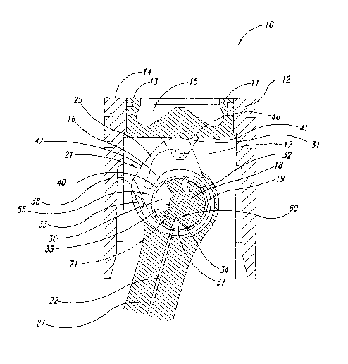
For example, as shown in Figure 1, the inner piston 11 can be
selectively positioned so that a top surface of the inner piston 13 is
substantially
adjacent to a top surface of the outer piston 14 to produce a high compression
ratio. As shown in Figure 2, the inner piston can also be selectively dropped
to
a position where the flop surface of the inner piston 13 is lower than the top
surface of the outer piston 14 to produce, upon demand, a lower compression
ratio. Movement of the inner piston is caused by the rotation of an actuator
assembly 55 consisting of a cam assembly 21 which pivots about a wrist pin 18
residing in the outer piston 14.
In an engine cylinder, the high position shown in Figure 1 yields a
greater degree of compression relative to expanded volume as compared to
when the inner piston 11 is selectively positioned lower within the outer
piston
12, as shown in Figure 2. Since greater engine efficiencies at normal
operating
loads can be achieved when the fuel or air/fuel mixture within a cylinder is
compressed to a greater degree, operation of an ICE in this high compression
ratio mode can result in improved fuel economy.
According to the principles of the present invention, the inner and
outer pistons 11, 12 are coupled to a connecting rod 27 in an identical manner
for each of the preferred embodiments discussed herein.
Similar to the assembly of most conventional ICEs, the outer
piston 12 of the present invention is rigidly embedded to a wrist pin 18, and
a
connecting rod 27 pivotably engages the wrist pin 18. Figure 7 depicts an
enlarged view of the connecting rod 27 showing wrist pin bearing surfaces 81 a
and 81b that pivotably engage the wrist pin 18, while a crankshaft bearing
surface 82 pivotably engages a crankshaft (not shown).
As shown in Figures 1, 2 and 4, a cam assembly 21 including a
cam 16 is pivotably mounted on the wrist pin 18. A cam bearing sleeve 40 is
interposed between the cam 16 and the wrist pin 18, providing a~bearing
surface 93 between the cam bearing sleeve 40 and the cam 16.
As shown in Figures 1 and 2, the inner piston 11 is coupled to the
cam 16 via a pin boss 31 and a retaining pin 17. The pin boss 31 may be
6
CA 02493093 2005-O1-12
WO 2004/015256 PCT/US2003/025043
affixed to the bottom surface 41 of the inner piston 11, or it may be integral
to
the inner piston 11. As shown in Figure 3, the retaining pin may alternatively
be
provided as a pair of retaining pins 17a and 17b coupled to the cam 16 to
engage the inner piston 11 via the pin boss 31.
Discussed now are various embodiments in which the principles
of the present invention may be employed. It is to be understood that the term
"high compression ratio mode" refers to a compression ratio that is higher
than
the compression ratio of a same mounted piston assembly 10 in a low
compression ratio mode, and one skilled in the art will recognize that the
resulting numerical compression ratio difference between operating in a first
position and a second position, as well as the range of distances in which the
inner piston may be lowered within an outer piston is a matter of design
choice,
where the tradeoffs between engine efficiency and engine performance must be
considered. Further factors influencing the design choice include the ICEs
cylinder diameter, connecting rod length, cylinder head and valve design.
In a preferred embodiment, the piston assembly 10 operates
intermittently. To achieve the goal of improved engine efficiency, the piston
assembly 10 operates in a first position/high compression mode under normal
road loads. When a sensor determines that the compression ratio should be
reduced, for example, if the demand for power is increasing peak cylinder
pressures to the detriment of the ICE's performance, the compression ratio is
lowered by moving the inner piston 11 to a position lower than the outer
piston
12. In a low compression mode, the top face of the inner piston 13 is
positioned lower than the top face of the outer piston 14. Similarly, when a
return to normal road load conditions is detected, the inner piston 11 is
returned
to the first position.
Figure 1 shows the piston assembly 10 in a first position. The
inner piston 11 is slidably mounted within an outer piston 12. The high
compression ratio mode is achieved when the top face of the inner piston 13 is
substantially flush with the top face of the outer piston 14. As the piston
assembly 10 reciprocates within an engine cylinder, the assembly 10 remains in
7
CA 02493093 2005-O1-12
WO 2004/015256 PCT/US2003/025043
this position as long as no force acts to rotate the cam 16 about the wrist
pin 18.
Even if inertial forces on a rapidly reciprocating cam assembly 21 do exert a
rotational tendency on the cam 16, a spring 19 exerts force on the cam 16
sufficient to counteract this force and the cam 16 remains stable and
maintains
the high compression ratio mode.
In this preferred embodiment, the cam assembly 21 comprises a
cam 16, and a flange 25 having a first flat portion 46 and a second flat
portion
47. When in the first position, a bottom surface 41 of the inner piston 11
rests
on the first flat portion 46, and the flange 25 eccentrically engages a
retaining
pin 17 to maintain the high compression ratio mode. The cam 16 is held by the
force of a retention spring, which, in the present embodiment, is a clock
spring
19 with a fixed end 32 embedded in, or otherwise affixed to, the wrist pin 18.
The clock spring 39 also has a free end 38, which is slidably cradled by a
spring
cradle 33 mounted upon or integral with the cam 16. In an alternate
embodiment, shown in Figure 3, the spring may also consist of a pair of clock
springs, 19a and 19b, to provide symmetry of force.
The second position of the present embodiment is shown in
Figure 2. The inner piston 11 is receded downward within the outer piston 12
so that the top surface of the inner piston 13 is below the top surface of the
outer piston 14. The bottom surface 41 of the inner piston 11 rests stably on
a
second flat portion 47 of the cam 16, with the cam 16 again restrained by the
retaining pin 17.
As the inner piston 11 is moved from the first position to the
second position, good mixing and combustion is retained in both the high and
low compression ratio modes because a piston bowl 15 resides within the
moving inner piston 11 and therefore does not change shape, only changing its
relative distance from the top of the cylinder when at TDC. Since the shape of
the piston bowl 15 is unchanged as the inner piston 11 moves, a further
advantage of the present invention; applicable to all of the embodiments
discussed herein, is that changes in the charge-mixing and combustion
properties of the combustion chamber are minimized.
8
CA 02493093 2005-O1-12
WO 2004/015256 PCT/US2003/025043
As shown in Figures 5 and 6, an actuator assembly 55 is coupled
to a fluid delivery system 60 to move the inner piston 11. The actuator
assembly 55 comprises the cam assembly 21, the spring 19, and rotary
hydraulic chamber 36 having a rotary hydraulic piston 35.' In a preferred
embodiment, the wrist pin 18 and rotary hydraulic chamber 36 are integral to
each other. Figure 5 shows that the cam 16 houses the rotary hydraulic piston
35 which extends through the cam bearing sleeve 40 and into the rotary
hydraulic chamber 36 that is provided in the wrist pin 18. The rotary
hydraulic
piston 35 is affixed within the cam 16 by means of pin 52 which may employ a
threaded, press fit, or other mode of connection. A piston seal 51 of
elastomer
or similar material is provided on the bearing surface of the rotary hydraulic
piston 35 to prevent fluid that enters and exits the hydraulic chamber 36 from
leaking past the rotary hydraulic piston 35.
Movement of the actuator assembly 55 is caused by the delivery
of a volume of fluid, at a pressure of several bar or more, from a fluid
source
(not shown) coupled to a bore 22 provided in the connecting rod 27. In a
preferred embodiment, the pressurized fluid is engine oil, however, it is to
be
understood that various hydraulic fluids, as known to one skilled in the art,
may
also be employed.
In a preferred embodiment for delivering the fluid to the actuator.
assembly 55, a fluid delivery system 60 is coupled to the fluid source and
comprises the connecting rod bore 22, a fluid supply passage 34, a fluid entry
port 37, and an internal radial passage 71 within the wrist pin 18. The fluid
passage 34 exits at an angle perpendicular to the fluid entry port 37 and
proceeds parallel to the wrist pin 18 until it turns into radial passage 71,
to enter
the rotary hydraulic chamber 36: This arrangement is shown.in Figures 3 and
6.
As the piston assembly 10 reciprocates within an engine cylinder,
fluid communication between the connecting rod bore 22 and the rotary actuator
chamber 36 is preferably maintained even as the angle of the connecting rod 27
about the wrist pin 18 varies by perhaps twenty degrees or more. Comparing
9
CA 02493093 2005-O1-12
WO 2004/015256 PCT/US2003/025043
Figures 1 and 2, which depict the angle of the connecting rod 27 at its two
extremes, it may be seen that the bearing side of the fluid entry port 37 has
a
sufficient width to maintain fluid communication with the connecting rod bore
22
as the connecting rod 27 rotates about the wrist pin 18. This arrangement is
also shown in Figure 6.
Returning to the present embodiment for actuating the inner
piston 11, fluid via the fluid delivery system 60 enters the rotary hydraulic
chamber 36, displacing the rotary hydraulic piston 35, causing the cam 16 to
overcome the biasing force of the spring 19 and rotate the cam assembly 21.
Owing to the eccentric radius of the inner surface of the flange 25 about the
centerline of the wrist pin 18, and the engagement of the flange 25 with the
retaining pin 17, a vertical displacement of the inner piston 11 with respect
to
the outer piston 12 results from the rotation of the cam 16. This low
compression ratio mode is maintained as long as sufficient fluid remains in
the
rotary hydraulic chamber 36 to maintain the position of the displaced
hydraulic
piston 35.
A volume of fluid to activate the low compression ratio mode is
delivered in response to a control signal generated by a control system
designed
to monitor the operating conditions within an ICE. Preferably, the control
system
is comprised of a central processing unit and one or more valves for
regulating
the pressurized fluid pulse.
In one preferred embodiment, the control system monitors the
power demanded by the operator of the engine. In a vehicle application, for
example, if the accelerator pedal is depressed to a position corresponding to
a
power demand level likely to raise peak cylinder pressures to a detrimental
level,
a first command signal is sent and a control valve is opened. Pressurized
fluid is
conducted from the fluid source into fluid passages provided within the
crankshaft
and into a bearing interface port provided in the crankshaft bearing surface
82
between the crankshaft and the connecting rod 27. (This method of supplying
fluid to a connecting rod through a bearing interface port in a
CA 02493093 2005-O1-12
WO 2004/015256 PCT/US2003/025043
crankshaft/connecting-rod bearing is known in the prior art and is not
detailed
here.)
After entering the connecting rod 27, fluid proceeds through the
connecting rod bore 22, the fluid entry port 37, and fluid supply passage 34
into
the rotary hydraulic chamber 36. The chamber 36 quickly becomes filled with
pressurized fluid and the rotary hydraulic piston 35 becomes fully displaced.
If
the piston assembly 10 is installed in an ICE having a closed bearing system,
the valve may be closed at this point, as fluid within the hydraulic chamber
36
will remain contained within chamber 36 until a command is given to release
the
fluid. If however, the piston assembly 10 is installed in an ICE having an
open
bearing system design, as is the case with most conventional engines having
journal bearings, the valve remains open and continues to supply fluid to the
rotary hydraulic chamber 36, thereby maintaining the displacement of the
hydraulic piston 35 and, in turn, the low compression ratio mode.
As driving conditions change, and the need for more power is no
longer required, the accelerator pedal will return from the depressed
position,
and a second command signal is sent to either re-open the digital valve if it
was
previously closed, or to cease the continuous supply of fluid, depending again
on the ICE's bearing system. This second signal allows the fluid held in the
rotary hydraulic chamber 36 to empty via a return path through the passages by
which it entered, or to a low-pressure sink. As fluid begins to exit, the
force of
the spring 19 once again is sufficient to counteract the force of the fluid,
and
causes the cam 16 to rotate sufficiently that the bottom surface 41 of the
inner
piston 11 no longer rests on the second flat portion 47 of the cam 16.
Inertial
forces acting on the reciprocating piston assembly exert an additional lifting
force on the inner piston 11, thus supplementing the force of the spring 19 in
causing the cam 16 to rotate back into a high compression ratio mode. Resting
again on the first flat portion 46 of the cam 16, and additionally restrained
by the
retaining pin 17, the inner piston 11 is once again in the stable first
position
. shown in Figure 1.
11
CA 02493093 2005-O1-12
WO 2004/015256 PCT/US2003/025043
In an ICE with multiple cylinders, a command signal may be
provided to each piston assembly within each cylinder, or to a subgroup of
piston assemblies 10. In this way, the timing used to vary the compression
ratio
may be further tuned to optimize engine efficiency and performance.
In another preferred embodiment, the control system monitors the
cylinder pressure to determine when a signal should be sent to vary the
compression ratio. As with the previous embodiment, when the cylinder
pressure is at an undesirable level, a first signal is sent to lower the inner
piston
11. When the cylinder pressure returns to a level where the compression ratio
may be maximized without compromising performance, a second signal is sent
to raise the inner piston 11. It is to be understood by one skilled in the
art, that
there are numerous other means in which a control system can monitor the
operating conditions within an ICE and the invention is not limited to those
discussed herein.
Another preferred embodiment for actuating the inner piston is
shown in Figure 8. Actuation of the inner piston 11 from a first position to a
second position is similar to the previous embodiment discussed according to
Figures 1 and 2; however, the actuator assembly 155 provides a coil spring 119
within a control cylinder 23 in contrast to the clock spring 19 of the
previous
embodiment. Also, as opposed to the rotary hydraulic chamber 36 of the
previous embodiment, here, the control cylinder 23 comprises a hydraulic
chamber 136 externally coupled to the wrist pin 18. As best seen in Figures 10
and 11, a plunger-type hydraulic piston 135 is positioned in hydraulic chamber
136. A longitudinal bore 28 is provided in stem 24, creating a path of fluid
communication between stem port 73 and chamber 136.
The fluid delivery system 60 of the present embodiment for
actuating the inner piston is also similar to the previously described
embodiment. Further, a bearing surface 93 is coupled to the internal radial
passage 71 and to a cam bearing surface passage 72 which is in open
communication with the stem bore 28. In this embodiment, the cam assembly
12
CA 02493093 2005-O1-12
WO 2004/015256 PCT/US2003/025043
21, the coil spring 119, the hydraulic chamber 136, and the plunger type
hydraulic piston 135 comprise an actuator assembly 155.
With actuator assembly 155, the low compression mode shown in
Figure 9 is achieved via a command signal that is issued in a similar fashion
to
that described for Figure 2. Issuance of the control signal causes fluid to
fill the
hydraulic chamber 136 resulting in a displacement of the hydraulic piston 135,
stem 24, and pivot 26, which results in a rotation of the cam 16 to lower the
inner piston 11 to a stable low compression ratio mode. As in the previously
described embodiment, release of fluid from the cylinder chamber 44 in a
reverse manner allows the restorative force of the coil spring 119 to initiate
a
return to a high compression ratio mode. This process is assisted, as before,
by inertial forces, until the stable first position shown in Figure 8 is
restored.
Each of the embodiments described herein moves the inner piston
11 quickly, in response to the command signals. This ability to quickly vary
the
compression ratio is a further advantage of the present invention over known
prior art. When an ICE is calibrated to operate at a high compression ratio
during normal loads, the demand for further power output can result in
excessive peak cylinder pressures. The detrimental effects associated with
such pressure increases may be minimized by lowering the compression ratio
to timely provide additional space in the combustion chamber.
Although specific embodiments for actuating the inner piston are
discussed herein, it is to be understood by one skilled in the art that there
are a
number of ways in which a first member slidably mounted within a second
member may be actuated, and the means of actuating the inner piston 11
relative to the outer piston 12 is not to be limited to those discussed
herein. As
will be understood by one of ordinary skill, there a number of ways to channel
fluid from a fluid source to the piston and cylinder region of an ICE, and the
fluid
delivery system 60 described herein is not to limit the scope of this
invention.
A further embodiment of the present invention employs yet
another system for actuating the inner piston 11, that is capable of providing
either an intermittent or a continuously variable compression ratio. More
13
CA 02493093 2005-O1-12
WO 2004/015256 PCT/US2003/025043
particularly, as shown in Figure 12, a plunger type hydraulic piston 135
divides
the hydraulic chamber 136 into a first and second region, 136a and 136b, and
the stem 24 has two stem bores 128, 129. Fluid is supplied to bores 128,129
via two fluid delivery systems 60a and 60b, respectively. As shown in Figure
13, each delivery system 60a and 60b has a connecting rod bore 122, a fluid
entry port 137, a fluid supply passage 134, a radial passage 171, a cam
bearing
surface passage 172, and a piston stem port 173, with fluid delivery system
60a
in open communication with stem bore 128 and fluid delivery system 60b in
open communication with stem bore 129.
The present embodiment dispenses with the coil spring 119, and
the restorative force is provided by a hydraulic means. For example, to
actuate
a low compression ratio mode, a control signal as previously described
supplies
a volume of fluid via fluid delivery system 60b into chamber 136b. Fluid in
chamber 136a is thereby forced out via fluid delivery system 60a to a low-
pressure source, and a low compression ratio position is attained. To return
to
a high compression ratio mode, fluid in chamber 136b is allowed to exit via
the
reverse path by which it entered, while pressurized fluid is returned to
chamber
136a by the reverse path by which it exited.
A significant advantage of the embodiment shown in Figures 12
and 13 is the ability to achieve a multi-stage or continuously variable
compression ratio, rather than the discrete two-mode compression ratio
variation of the previous embodiments. For example, by directing selected
volumes of fluid into chambers 136a and 136b, balancing forces may be
generated on opposite sides of piston 135, such that piston 135 resides in a
selected, stable position between the two extreme modes depicted in the
Figures. Such a configuration would result in a compression ratio between the
high compression ratio mode and low compression ratio mode.
As will be understood by one of ordinary skill, fluid delivery may
alternatively be provided to chambers 136a and 136b by reverting to the single
fluid delivery system 60 of Figure 9 to conduct fluid only to chamber 136b,
and
connecting chambers 136a and 136b by an external fluid passage, such as a
14
CA 02493093 2005-O1-12
WO 2004/015256 PCT/US2003/025043
flexible line or other channel, to control flow between chambers 136a and 136b
by a conventionally known valuing system.
In addition to the numerous advantages achieved by several of
the embodiments described above, the present invention also serves to
minimize squish variations. Squish area is the volume between the top of a
piston at top dead center to the bottom of a cylinder head. Since it is
difficult for
the fuel or air/fuel mixture to reach this area, a large squish area leads to
lower
engine efficiencies. Most prior art devices known to vary the compression
ratio
have the undesired effect of simultaneously varying the squish area by a
significant degree. But with the present invention, as is shown in Figure 14,
the
distance 96 between the top surface of the outer piston 14 and the bottom
surface 97 of a cylinder head 95 when the piston assembly 10 is positioned at
top dead center remains substantially constant, independent of the variable
location of the inner piston 11.
From the foregoing it will be appreciated that, although specific
embodiments of the invention have been described herein for purposes of
illustration, various modifications may be made without deviating from the
spirit
and scope of the invention. Accordingly, the invention is not limited except
as
by the appended claims.
15