Note: Descriptions are shown in the official language in which they were submitted.
CA 02493131 2005-01-20
- 1 -
END POSITION DETECTOR FOR MOVABLE SWITCH PARTS
The invention pertains to an end position detector for movable
switch parts which comprises a rod assembly and a housing,
into which the rod assembly penetrates and in which at least
one sensor for sensing an end position of the rod assembly is
arranged.
Switch operating devices for movable switch parts, in
particular tongue blades or switch points, which are provided
with an end position detector are generally known from the
pertinent state of the art. In known switch operating devices,
the movable switch part is mechanically driven with the aid of
an electric or hydraulic switch drive. In addition, a separate
interlocking device or an interlocking device that is
integrated into the switch drive, as well as a separate end
position detector, is provided. End position detectors of this
type are used for mechanically sensing the current state of
the switch and for generating a signal, based on which it can
be reliably ascertained if the switch was correctlv shifted
and whether the closed tongue and the open tongue are
respectively situated in their correct end position or not.
The end position detector comprises a rod assembly that
essentially extends transverse to the longitudinal direction
of the rails and is displaced in the longitudinal direction of
the rod assembly when the switch is shifted. The position of
the rods is determined with the aid of electromechanical
transducers that, for example, are realized in the form of
proximity switches or switch contacts and usually arranged in
a housing that is mounted laterally of the switch on a
sleeper.
In addition to the embodiment, in which the end position
detector is realized in the form of a separate unit, it has
also been proposed to integrate the end position detector into
a common housing together with the switch drive, for example,
in DE 1755105. DE 29917829 U1 discloses a different embodiment
CA 02493131 2005-01-20
- 2 -
with a continuous rod, the two rod sections of which can be
telescopically extended in a spring-loaded fashion. In this
case, the end position contact switches are realized in the
form of switching fingers that are rigidly connected to the
rod and cooperate with proximity switches. In alternative
solutions, the rod is provided with grooves, into which
switching levers engage such that they are able to trigger the
end position switch. One example of such an embodiment is
disclosed in US 5,669,587.
However, known end position detectors have one common
disadvantage, namely that their functional integrity depends
on a series of external factors that cannot be directly
influenced. For example, the vibrations of the movable switch
part which are produced when a train travels over the switch
can be transmitted onto the rod assembly and lead to
malfunctions or the faulty triggering of the end position
contact switches. In addition, mechanical tensions in the rod
assembly or even distortions thereof may occur as a result of
changes in the interconnected mass, for example, thermal
expansions of the tongue blade. These mechanical tensions or
distortions not only result in an increased friction between
the rod assembly and the housing, but may also cause the rod
assembly to become jammed or tilted. In any case, the proper
function of the end position detector is significantly
impaired.
The present invention is based on the objective of developing
an end position detector that delivers reliable switching
signals independently of external influences, wherein an exact
adaptation to the respective travel stroke of the movable
switch part can be realized, and wherein even slight
deviations from the end position result in the end position
switch not being actuated. In addition, the end position
detector should have a compact design and, in particular, have
such dimensions that it can be installed in a trough-like
sleeper.
CA 02493131 2005-01-20
- 3 -
According to the invention, this objective is attained by
essentially realizing the end position detector in such a way
that the rod assembly is connected to the movable switch part
such that it can be pivoted in a vertical plane that lies
transverse to the longitudinal direction of the rails, and
that the rod assembly comprises at least one rod of circular
cross section which in its region that penetrates into the
housing in a sealed fashion carries on its periphery at least
one switching flank that cooperates with the switch contact.
Since the rod assembly is connected to the movable switch part
such that it can be pivoted in a vertical plane that lies
transverse to the longitudinal direction of the rails and the
pivot support is preferably realized by utilizing elastic
connecting elements and/or spherical bearings, vibrations of
the tongue blade or the switch point are compensated and not
transmitted onto the rod. This means that such vibrations
alone can no longer trigger the end position switch, and that
the reliability of the detector can be improved. The tilting
moments which additionally act upon the movable parts while a
train travels over the switch can also be absorbed due to the
ability to pivot the rod assembly about an axis that
essentially extends in the longitudinal direction of the rails
in the joint or in the elastic connecting element.
It is also impossible to prevent torsional moments from acting
upon the rod assembly. This is the reason why the invention
proposes that the rod assembly comprises at least one rod of
circular cross section that carries on its periphery at least
one switching flank that cooperates with a switch contact,
namely in the region that penetrates into the housing in a
sealed fashion. Due to this configuration, the functional
integrity of the end position detector also remains unaffected
under torsional stresses or if the rod assembly, in particular
the rod of circular cross section, is distorted. The circular
cross section of the rod ensures that the housing always
remains sealed in the region, in which the rod penetrates into
CA 02493131 2005-01-20
- 4 -
the housing. In addition, the switching flank that is arranged
in this region and cooperates with a switch contact ensures
that the end position switch is only actuated in the exact end
position, namely independently of interfering external
influences.
In one preferred embodiment of the end position detector
according to the invention, the housing is connected to a
stationary part of the switch such that it can be pivoted in a
vertical plane that lies transverse to the longitudinal
direction of the rails. This means that a pivot support about
an axis that extends in the longitudinal direction of the
rails, i.e., in a vertical plane that lies transverse to the
longitudinal direction of the rails, is not only realized on
the rail side, but also on the side situated opposite of the
movable switch part. This flexible support makes it possible
to even better isolate the end position detector from tilting
moments, vibrations or other mechanical tensions. In this
case, the housing is connected to a stationary part in a
pivoted fashion, wherein the sleeper or trough-like sleeper
usually serves as the stationary part.
According to one preferred embodiment, another improvement is
achieved by connecting the rod assembly to the movable switch
part such that it can be displaced in the longitudinal
direction of the rails. This embodiment also pertains to the
mounting of the rod assembly on the rail side. Since the rod
assembly can be longitudinally displaced relative to the
movable switch part, this embodiment makes it possible to take
into account that tongue blades and switch points are
subjected to thermal expansions. However, these thermal
expansions cannot be transferred onto the rod assembly because
this would impair the proper function of the end position
detector and its ability to precisely sense the end position.
With respect to constructive considerations, this is
advantageously realized in such a way that the rod assembly is
connected to a vertical bolt that is guided in a sliding
CA 02493131 2005-01-20
- 5 -
fashion in an oblong hole, wherein this oblong hole
essentially extends in the longitudinal direction of the rails
and is arranged in a base plate of the movable switch part.
The oblong hole makes it possible to longitudinally displace
the rod assembly relative to the movable switch part. Since
the connection between the rod assembly and the base plate
containing the oblong hole is produced with the aid of a
vertical bolt, the rod assembly can be simultaneously pivoted
about an axis that lies perpendicular to the plane of the
rails such that a certain flexibility is also achieved in this
respect.
The pivot support or flexibility of the end position detector
on the rail side as well as the side of the housing naturally
cannot cause any play or flexibility in the direction of the
travel stroke, i.e., in the longitudinal direction of the rod,
because an exact detection of the end position would otherwise
be impossible. Consequently, the individual bearing points
need to be realized in such a way that the travel movement of
the movable rail part is directly transmitted onto the rod
assembly. In this context, the coupling of the rod assembly on
the rail side is advantageously realized in such a way that
the bolt contains a spherical contact surface or carries a
sliding ring with spherical contact surface in the region of
its section that penetrates into the oblong hole. According to
another preferred embodiment, the rod is connected to the bolt
in an angularly rigid fashion, preferably at an angle of 902,
via a connecting element.
When a train travels over a switch, it is impossible to
prevent the movable switch part, i.e., the tongue blade or the
switch point, from being lowered and raised under the
influence of the rolling load. This is the reason why the end
position detector according to the invention is advantageously
realized in such a way that the rod or the connecting element
engages on the bolt via spring elements that act in the
direction of the longitudinal axis of the bolt. This makes it
CA 02493131 2005-01-20
- 6 -
possible to also absorb these vertical movements of the
movable switch part, namely without subjecting the rod to
excessive mechanical stresses that could cause the rod to tilt
or jam in the housing.
In order to precisely adapt the end position detector to the
respective travel stroke of the switch, the invention proposes
that the switching flank can be adjusted in the axial
direction of the rod, wherein the switching flank is
advantageously realized in the form of the end face of a tube
that can be screwed on the rod. This means that the axial
length of the switching flank can be varied and adapted to the
respective travel stroke by turning the tube. However, it
would also be conceivable to realize a direct adjustment. In
this case, the effective length of the rod can be varied and
adapted to the respective travel stroke of the movable switch
part, wherein the rod is preferably provided with an outside
thread on its end that faces the movable switch part such that
it can be screwed into an inside thread of a part that is
connected to the movable switch part, preferably the
connecting element, and fixed in the respective position.
According to another advantageous embodiment, the rod is
prevented from tilting or jamming due to the fact that the
housing comprises a guide tube, the length of which is greater
than the maximum travel stroke of the movable switch part and
in which the rod is guided in a sliding fashion. The sliding
guidance of the rod in the guide tube results in an axial
guidance over a distance that is greater than the maximum
travel stroke of the movable switch part. Consequently, the
switching flank that is arranged on the rod assembly and
cooperates with a switch contact is situated within the guide
tube independently of the respective position of the movable
switch part. Due to these measures, the sensitive region of
the end position switch is protected from dirt and the precise
interaction with the switch is not impaired. In this case, the
switch is realized with a spring-loaded plunger that engages
CA 02493131 2005-01-20
- 7 -
into the groove defined by the switching flank in the correct
end position of the movable switch part. Due to this design,
the spring-loaded plunger only engages in the correct end
position and only into the groove defined by the switching
flank in order to trigger the switching process of the end
position switch with positive opening operation and to signal
the correct end position of the movable switch part to a
distant monitoring station. Since the rod length and the axial
position of the switching flank can also be adapted to the
respective travel stroke, it is possible to exactly place the
switching flank at the position required for the cooperation
with the spring-controlled switch. In any other incorrect end
position of the monitored part, the plunger is positively
actuated by the rod such that the switch is also positively
opened and the reaching of the correct end position is not
signalled, namely independently of the fact how slightly the
rod is spaced apart from this end position.
The end position detector can be realized in a very compact
fashion, wherein a particularly protected arrangement is
achieved if the rod assembly and the housing are, according to
one preferred embodiment, accommodated in a trough-like
sleeper or in a stationarv switch part.
The invention is described in greater detail below with
reference to one embodiment that is schematically illustrated
in the figures. Figure 1 shows a vertical section through a
switch with a movable switch point and an end position
detector arranged in the trough-like sleeper. Figure 2 shows a
top view of the switch according to Figure 1, Figure 3 shows a
detail of the rod coupling on the rail side, Figure 4 shows a
detail of the housing and Figure 5 shows a detail of a
modified variation of the housing according to Figure 4.
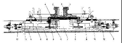
Figure 1 shows a vertical section through a switch, wherein
the reference signs 1 and 2 identify the guardrails and the
reference sign 3 identifies the movable switch point. This
CA 02493131 2005-01-20
- 8 -
movable switch point is illustrated with continuous lines in
the position in which it adjoins the guardrail 1 and with
broken lines in the position in which it adjoins the guardrail
2. The switch point 3 is connected to a base plate 4 that is
supported on the slide chair of a trough-like sleeper 5. In
order to shift the switch point 3 between the two contact
positions or end positions, a driving device 6 is provided
which is connected to the base plate 4 by means of a coupling
element 7 that is not illustrated in greater detail. The end
position detector is realized separately of the driving device
and comprises a rod 8 that is coupled to the base plate 4 by
means of an intermediate element 9 and a bolt 10. The rod 8
penetrates into a guide tube 11 that forms part of the housing
12. A switch contact for detecting the correct end position of
the rod assembly is arranged in the housing 12 as described in
greater detail below, wherein the switch contact cooperates
with a switching flank 13 arranged on the rod 8. The switch
point 3 is connected to a separate end position detector for
each end position, wherein the end position detector
illustrated on the right in this figure serves for determining
whether the switch point 3 adjoins the guardrail 1 and the end
position detector illustrated on the left serves for
determining whether the switch point adjoins the guardrail 2.
Figure 2 shows an enlarged top view of the end position
detector according to the invention, wherein certain
components that are not required for comprehending the
invention and do not form part of the end position detector
were omitted in order to provide a better overview. The
reference sign 3 identifies the switch point that is fixed on
the base plate 4. This top view indicates that the base plate
4 is provided with an oblong hole 14, in which the bolt 10 is
guided such that it can be longitudinally displaced in the
direction of the double arrow 15. The rod 8 penetrates into
the guide tube 11 that forms part of the housing 12. The
housing 12 accommodates an end position switch 16 that engages
into the groove defined by the switching flank 13 when the
CA 02493131 2007-05-17
- 9 -
correct end position is reached and transmits a corresponding
signal to a distant monitoring station. A bolt 17 connects the
housing 12 to a stationary part of the trough-like sleeper 5,
namely the fork section 18, in an articulated fashion such
that the housing can be pivoted about the axis 19. The fork
section 18 also serves for realizing the stationary coupling
of the switch drive 6.
Figure 3 shows an enlarged representation of the coupling of
the rod 8 on the rail side. As mentioned above, the bolt 10
penetrates into the oblong hole 14 of the base plate 4,
wherein this figure indicates that the bolt 10 carries
spherical contact surfaces 20 in order to enable the bolt to
pivot relative to the base plate 4 about the axes 21 that
essentially extend in the longitudinal direction of the rails.
The bolt 10 is secured by means of a counterpart 22, wherein
the bolt 10 cooperates with a safety pin 24 via spring
elements or seals-23 such that a relative displacement can be
realized in the vertical direction as indicated by the double
arrow 25. The connection with the rod 8 is realized with the
aid of the intermediate element 9, wherein the rod 8 is
provided with a thread 26 such that the effective length of
the rod can be adapted to the respective travel stroke of the
movable switch part by turning the rod. The lock nut 27 serves
for securing the adjusted position of the rod. However, the
adaptation to the travel stroke can also be realized with the
arrangement illustrated in Figure 5, in which the rod 8 may be
rigidly connected to the connecting element 9.
Figure 4 shows an enlarged representation of the housing which
indicates that the rod 8 penetrates into the guide tube 11 in
a sealed fashion, namely with the aid of seals 28. The spring-
controlled switch 16 that is equipped with a spring-loaded
plunger 29 is arranged in the housing 12. The spring-loaded
plunger 29 is able to engage into the groove defined by the
switching flank 13, wherein the spring-controlled switch 16 is
only able to signal that the correct end position is reached
CA 02493131 2007-05-17
- 10 -
in this case. In all other instances, no switching signal is
generated due to the positive opening operation of the switch.
The precise adjustment of the switch is realized with the aid
of the adjusting screw 30. The cable connector is identified
by the reference sign 31. In order to allow an external
inspection of the switch, the housing 12 is realized with a
transparent cover 32 such that an additional on-site control
can be carried out.
Figure 5 shows a modified embodiment of the rod assembly
section that penetrates into the housing 12. A tube.36 that
carries the switching flank 13 on its end face is screwed on a
threaded section 33 of the rod 8. This means that the position
of the switching flank 13 can be axially adjusted and adapted
to different travel strokes by turning the square part 34 of
the tube 36. The lock nut 35 serves for fixing and securing
the respectively adjusted position.