Note: Descriptions are shown in the official language in which they were submitted.
CA 02493526 2005-O1-21
Doc. No. 151-24 CA Patent
APPARATUS AND METHOD FOR CONTROLLABLY AFFECTING THE
TEMPERATURE OF FAIMS COMPONENTS
FIELD OF THE INVENTION
[001] The instant invention relates generally to High Field Asymmetric
Waveform Ion
Mobility Spectrometry (FAIMS). More particularly, the instant invention
relates to an
apparatus for providing control for affecting the temperature in a FAIMS
region of a
FAIMS system and a method of improving the separation capability of a FAIMS
system.
BACKGROUND OF THE INVENTION
[002] High sensitivity and amenability to miniaturization for field-portable
applications have helped to make ion mobility spectrometry (IMS) an important
technique for the detection of many compounds, including narcotics,
explosives, and
chemical warfare agents as described, for example, by G. Eiceman and Z. Karpas
in their
book entitled "Ion Mobility Spectrometry" (CRC, Boca Raton, 1994). In IMS, gas-
phase
ion mobilities are determined using a drift tube with a constant electric
field. Ions are
separated in the drift tube on the basis of differences in their drift
velocities. At low
electric field strength, for example 200 V/em, the drift velocity of an ion is
proportional
to the applied electric field strength, and the mobility, K, which is
determined from
experimentation, is independent of the applied electric field. Additionally,
in IMS the
ions travel through a bath gas that is at sufficiently high pressure that the
ions rapidly
reach constant velocity when driven by the force of an electric field that is
constant both
in time and location. This is to be clearly distinguished from those
techniques, most of
which are related to mass spectrometry, in which the gas pressure is
sufficiently low that,
if under the influence of a constant electric field, the ions continue to
accelerate.
[003] E.A. Mason and E. W. McDaniel in their book entitled "Transport
Properties of
Ions in Gases" (Whey, New York, 1988) teach that at high electric field
strength, for
instance fields stronger than approximately 5,000 V/cm, the ion drift velocity
is no longer
directly proportional to the applied electric field, and K is better
represented by KH, a
CA 02493526 2005-O1-21
Doc. No. 151-24 CA Patent
non-constant high field mobility term. The dependence of KN on the applied
electric field
has been the basis for the development of high field asymmetric waveform ion
mobility
spectrometry (FAIMS). Ions are separated in FAIMS on the basis of a difference
in the
mobility of an ion at high field strength, KH, relative to the mobility of the
ion at low field
strength, K. In other words, the ions are separated due to the compound
dependent
behavior of KH as a function of the applied electric field strength.
[004] In general, a device for separating ions according to the FAIMS
principle has an
analyzer region that is defined by a space between first and second spaced-
apart
electrodes. The first electrode is maintained at a selected do voltage, often
at ground
potential, while the second electrode has an asymmetric waveform V(t) applied
to it. The
asymmetric waveform V(t) is composed of a repeating pattern including a high
voltage
component, V,.~, lasting for a short period of time tH and a lower voltage
component, VL,
of opposite polarity, lasting a longer period of time t~. The waveform is
synthesized such
that the integrated voltage-time product, and thus the field-time product,
applied to the
second electrode during each complete cycle of the waveform is zero, for
instance VH tH
+ VL tt, = 0; for example +2000 V for IO ~s followed by -1000 V for 20 ps. The
peak
voltage during the shorter, high voltage portion of the waveform is called the
"dispersion
voltage" or DV, which is identically referred to as the applied asymmetric
waveform
voltage.
[005] Generally, the ions that are to be separated are entrained in a stream
of gas
flowing through the FAIMS analyzer region, for example between a pair of
horizontally
oriented, spaced-apart electrodes. Accordingly, the net motion of an ion
within the
analyzer region is the sum of a horizontal x-axis component due to the stream
of gas and
a transverse y-axis component due to the applied electric field. During the
high voltage
portion of the waveform, an ion moves with a y-axis velocity component given
by vH =
KHEH, where EH is the applied field, and K~~ is the high field ion mobility
under operating
electric field, pressure and temperature conditions. The distance traveled by
the ion
during the high voltage portion of the waveform is given by dH = vEttEi =
KHE,,ttt, where
t,i is the time period of the applied high voltage. During the longer
duration, opposite
polarity, low voltage portion of the asymmetric waveform, the y-axis velocity
component
2
CA 02493526 2005-O1-21
Doc. No. 151-24 CA Patent
of the ion is v~ = KEG, where K is the low field ion mobility under operating
pressure and
temperature conditions. The distance traveled is d~ = v~t~= KELt~. Since the
asymmetric
waveform ensures that (VH t,i) ~- (VL t~) = 0, the field-time products EHtH
and E~t~ are
equal in magnitude. Thus, if Kt~ and K are identical, d,~ and d~ are equal,
and the ion is
returned to its original position along the y-axis during the negative cycle
of the
waveform. If at EH the mobility KH > K, the ion experiences a net displacement
from its
original position relative to the y-axis. For example, if a positive ion
travels farther
during the positive portion of the waveform, for instance dti > d~, then the
ion migrates
away from the second electrode and eventually will be neutralized at the first
electrode.
[006] In order to reverse the transverse drift of the positive ion in the
above example,
a constant negative do voltage is applied to the second electrode. The
difference between
the do voltage that is applied to the first electrode and the do voltage that
is applied to the
second electrode is called the "compensation voltage" (CV). The CV prevents
the ion
from migrating toward either the second or the first electrode. If ions
derived from two
compounds respond differently to the applied high strength electric fields,
the ratio of KH
to K may be different for each compound. Consequently, the magnitude of the CV
that is
necessary to prevent the drift of the ion toward either electrode is also
different for each
compound. Thus, when a mixture including several species of ions, each with a
unique
KE~/K ratio, is being analyzed by FAIMS, only one species of ion is
selectively
transmitted to a detector for a given combination of CV and DV. In one type of
FAIMS
experiment, the applied CV is scanned with time, for instance the CV is slowly
ramped or
optionally the CV is stepped from one voltage to a next voltage, and a
resulting intensity
of transmitted ions is measured. In this way a CV spectrum showing the total
ion current
as a function of CV, is obtained.
[007] In short, a FAIMS device is one which effects ion separation on the
basis of the
dependence of ion mobility on the electric field strength. In FAIMS the ions
are
introduced into an analyzer region across which an rf frequency asymmetric
waveform is
applied such that the ions are alternately subjected to strong electric fields
and low
electric fields. The field-dependent change in the mobility of the ions causes
the ions to
drift towards the walls of the analyzer region. Since the dependence of ion
mobility on
CA 02493526 2005-O1-21
Doc. No. 151-24 CA Patent
electric field strength is compound specific, this leads to a separation of
the different ions,
and is referred to as the FAIMS separation or identically, the FAIMS
mechanism. In
order to transmit an ion of interest through the FAIMS analyzer region, its
drift towards
the analyzer wall is compensated by applying an appropriate DC voltage for
that ion. By
varying this compensation voltage, ions are separately transmitted through the
FAIMS
device.
[008] In an analytical instrument that includes (1) an atmospheric pressure
ionization
source (for example electrospray ionization (ESI)), (2) an atmospheric
pressure gas phase
ion separator (for example a high-field asymmetric waveform ion mobility
spectrometer
(FAIMS)) and (3) an ion detection system (for example a mass spectrometer, MS)
it
would be advantageous to provide each with independent control for affecting
some of
the operating conditions including, temperature and operating gas pressure.
The ion
source, FAIMS, and detection system (mass spectrometer) have significantly
different
requirements for achieving optimal performance. For example, a mass
spectrometer
usually operates at room temperature and with a very low pressure or vacuum
within the
mass spectrometer chamber. The ionization source preferably operates at
pressures close
to atmospheric, but at elevated temperature so as to assist in desolvation of
the ions. The
FAIMS electrodes may optimally operate near atmospheric pressure, but at a
temperature
below ambient.
SUMMARY OF THE INVENTION
[009] It is an object of the instant invention to provide a method and an
apparatus that
overcomes at least some of the :limitations of the prior art.
[0010] According to an aspect of the instant invention, there is provided an
apparatus
for separating ions, comprising: a FAIMS analyzer having an ion inlet for
receiving ions
into the FAIMS analyzer, the F,AIMS analyzer comprising a first electrode and
a second
electrode spaced apart from the first electrode, a space between the first
electrode and the
second electrode defining an analyzer region for separating a subset of ions
from the
received ions; a temperature sensor disposed for sensing a temperature that is
based upon
a temperature within the analyzer region and for providing an output signal in
4
CA 02493526 2005-O1-21
Doc. No. 151-24 CA Patent
dependence upon the sensed temperature; and, a temperature controller in
communication
with the temperature sensor, for controllably affecting the temperature within
the
analyzer region in response to the output signal of the temperature sensor.
[0011] According to another aspect of the instant invention, there is provided
a method
of separating ions, comprising: setting a temperature within an analyzer
region of a
FAIMS device to a predetermined value for supporting a separation of a subset
of ions
from an ionized sample; and, using the FAIMS device, separating the subset of
ions from
the ionized sample.
[0012] According to still another aspect of the instant invention, there is
provided a
method of separating ions, comprising: providing a FAIMS analyzer region
defined by a
space between a first electrode surface and a second electrode surface;
providing an
output signal from a temperature sensor, the output signal relating to a
temperature within
the FAIMS analyzer region; and, controllably affecting the temperature within
the
FAIMS analyzer region in dependence upon the output signal, for providing
approximately a predetermined temperature within the analyzer region
BRIEF DESCRIPTION OF THE DRAWINGS
[0013] Exemplary embodiments of the invention will now be described in
conjunction
with the following drawings, in which similar reference numerals designate
similar items:
[0014] Figure 1 is a simplified block diagram of an apparatus according to the
prior art;
[0015] Figure 2 is a longitudinal cross-sectional view of an apparatus
according to the
prior art;
(0016] Figure 3 is a simplified block diagram of an apparatus according to an
embodiment of the instant invention;
[0017] Figure 4 is a simplified block diagram of another apparatus according
to an
embodiment of the instant invention;
CA 02493526 2005-O1-21
Doc. No. 151-24 CA Patent
[0018] Figure 5 is a simplified block diagram of yet another apparatus
according to an
embodiment of the instant invention;
[0019] Figure 6 is a longitudinal cross-sectional view of an apparatus
according to an
embodiment of the instant invention and including a heated electrospray
ionization
source that is in fluid communication with an ion inlet of a FAIMS;
[0020] Figure 7 is a longitudinal cross-sectional view of an apparatus
according to an
embodiment of the instant invention and including a heated electrospray
ionization
source that is in fluid communication with an ion inlet of a FAIMS that is
equipped with
a heating/cooling system;
[0021] Figure 8a is an end view of a prior art side-to-side FAIMS having an
outer
electrode with a rectangular-shaped outer surface;
[0022] Figure 8b is an isometric view of the prior art side-to-side FAIMS that
is shown
at Figure 8a;
[0023] Figure 9 is a longitudinal cross-sectional view of an apparatus
according to an
embodiment of the instant invention and including heated electrospray
ionization source
that is in fluid communication with an ion inlet of a side-to-side FAIMS that
is supported
by an insulating block including a heat exchange passage;
[0024] Figure 10 is a longitudinal cross-sectional view of an apparatus
according to an
embodiment of the instant invention and including a heated electrospray
ionization
source that is in fluid communication with an ion inlet of a side-to-side
FAIMS including
a temperature-controlled inner electrode and temperature-controlled insulating
block, in
which the temperatures are adjusted using heat-exchange passages;
[0025] Figure 11 is a cross-sectional view of the apparatus of Figure 10, but
taken in a
plane that is normal to the page of Figure 10;
[0026] Figure 12 is a cross-sectional view of an apparatus according to an
embodiment
of the instant invention and showing the heating/cooling system for the inner
and outer
6
CA 02493526 2005-O1-21
Doc. No. 151-24 CA Patent
electrodes of a side-to-side FAIMS electrode system in which the outer
electrode is
formed from a rectangular block;
[0027] Figure 13 is a simplified block diagram showing a parallel flat-plate
FAIMS
including means for establishing a temperature gradient across the analyzer
region;
[0028] Figure 14 is a simplified end view of a cylindrical geometry FAIMS
having an
inner electrode and an outer electrode of radii 0.1 cm and 0.3 cm,
respectively, and
showing calculated electric field (E/N) values at about 5%, 50% and 95% of the
distance
from the surface of the inner electrode to the surface of the outer electrode,
absent a
temperature gradient;
[0029] Figure 15 is a simplified end view of a cylindrical geometry FAIMS
having an
inner electrode and an outer electrode of radii 0.1 cm and 0.3 cm,
respectively, and
showing calculated electric field (E/N) values at about 5%, SO% and 95% of the
distance
from the surface of the inner electrode to the surface of the outer electrode,
assuming a
+20K/mm temperature gradient beginning at the inner electrode and with 2500
volts
applied between the electrodes;
[0030] Figure 16 is a simplified end view of a cylindrical geometry FAIMS
having an
inner electrode and an outer electrode of radii 0.1 cm and 0.3 cm,
respectively, and
showing calculated electric field (E/N) values at about 5%, 50% and 95% of the
distance
from the surface of the inner electrode to the surface of the outer electrode,
assuming a
-20K/mm temperature gradient beginning at the inner electrode and with 2500
volts
applied between the electrodes;
[0031] Figure 17 is a simplified end view of a parallel flat-plate FAIMS
having a first
electrode and a second electrode spaced apart by 0.2 cm, and showing
calculated electric
field (E/N) values at about 5%, 50% and 95% of the distance from the surface
of the first
electrode to the surface of the second electrode, absent a temperature
gradient and with
2500 volts applied between the electrodes;
[0032] Figure 18 is a simplified end view of a parallel flat-plate FAIMS
having a first
electrode and a second electrode spaced apart by 0.2 cm, and showing
calculated electric
7
CA 02493526 2005-O1-21
Doc. No. 151-24 CA Patent
field (E~'N) values at about 5%, 50% and 95% of the distance from the surface
of the first
electrode to the surface of the second electrode, assuming a -20K/mm
temperature
gradient from left to right in the Figure and with 2500 volts applied between
the
electrodes;
[0033] Figure 19 compares a) the calculated electric field values for a
parallel flat-plate
FAIMS with electrodes spaced apart by 0.2 cm assuming a -20K/mm temperature
gradient from left to right in the Figure and with 2500 volts applied between
the
electrodes and b) calculated electric field values for a cylindrical geometry
FAIMS with
an inner electrode of radius 0.1 cm and an outer electrode of radius 0.3 cm,
assuming no
temperature gradient and with 2500 volts applied between the electrodes;
[0034] Figure 20 presents experimental data collected with an embodiment of
the
present invention showing the separation capability of a FAIMS analyzer in
dependence
of the temperature within the analyzer region with a) electrodes at room
temperature and
b) electrodes at 100°C;
[0035] Figure 21 presents experimental data collected with an embodiment of
the
present invention showing the dependence of ion transmission on temperature
gradients
imposed across the analyzer region;
[0036] Figure 22 is a simplified flow diagram of a method of separating ions
according
to an embodiment of the instant invention;
[0037] Figure 23 is a simplified flow diagram of another method of separating
ions
according to an embodiment of the instant invention; and,
[0038] Figure 24 is a simplified flow diagram of still another method of
separating ions
according to an embodiment of the instant invention.
8
CA 02493526 2005-O1-21
Doc. No. 151-24 CA Patent
DESCRIPTION OF EMBODIMENTS OF THE INSTANT INVENTION
[0039] The following description is presented to enable a person skilled in
the art to
make and use the invention, and is provided in the context of a particular
application and
its requirements. Various modifications to the disclosed embodiments will be
readily
apparent to those skilled in the art, and the general principles defined
herein may be
applied to other embodiments and applications without departing from the
spirit and the
scope of the invention. Thus, the present invention is not intended to be
limited to the
embodiments disclosed, but is to be accorded the widest scope consistent with
the
principles and features disclosed herein.
[0040] Throughout much of the following discussion it is assumed that the
FAIMS
electrodes are operated at atmospheric pressure, but at a temperature that
differs from that
of either the ionization source or of the mass spectrometer. Because ion
separation in the
FAIMS system is susceptible to changes in temperature, it is desirable to have
the ability
to controllably affect the temperature in the FAIMS region, which includes
both heating
and cooling. For example, a rise in temperature leads to a decrease in the
number density
of the gas (N) and therefore the operating electric field (E/N) appears to
increase. For
some ions this results in a drift of the CV values at which the ions are
transmitted through
FAIMS. In addition, an elevation in temperature may cause peaks in a CV
spectrum to
widen due to increased ion diffusion. Under such conditions, two ions that are
separated
at room temperature may fail to be separated at 100°C, for example.
Similarly, two ions
that fail to be separated at room temperature may be separated at 10°C
with cooled
FAIMS electrodes. Furthermore, the efficiency of transmission of some types of
ions
through FAIMS is a function of temperature. For instance, some types of ions
are subject
to thermal dissociation and therefore are more efficiently transmitted through
FAIMS in a
cool bath gas. Accordingly, it is desirable to be able to controllably affect
the
temperature of FAIMS to transmit the ions of interest. It is an advantage of
at least some
embodiments of the instant invention that the temperature of the FAIMS is
maintained at
a desired operating temperature. It is a further advantage that the
temperature of FAIMS
is controllably changed from a first desired operating temperature to a second
desired
operating temperature for different separations. It is an additional advantage
that the
9
CA 02493526 2005-O1-21
Doc. No. 151-24 CA Patent
temperature of FAIMS is independent of the temperature of external
instruments, such as
for instance the ionization source with which it is in fluid communication.
[0041] Referring now to Figure 1, shown is a simplified block diagram of an
apparatus
according to the prior art. The apparatus that is shown at Figure 1 is a
tandem
arrangement including an ion source 2, a FAIMS analyzer 4, and an ion
detecting device,
such as for example a mass spectrometer 6. The components 2, 4, and 6 are all
at about
room temperature during operation.
[0042] Referring now to Figure 2, shown is a longitudinal cross-sectional view
of an
apparatus according to the prior art. The apparatus includes an electrospray
ionization
source 10 that is disposed in fluid communication with an ion inlet 12 of a
FAIMS 14. In
Figure 2, the ions are formed near the tip of an electrospray needle 16 and
drift (under the
influence of an electrical field gradient) toward a curtain plate 18. A
curtain gas, which is
introduced below the curtain plate 18, divides into two flows, one of which
exits through
an aperture 20 in the curtain plate 18 so as to substantially prevent neutrals
and droplets
from entering the curtain plate aperture 20. Ions are driven against this flow
of gas by a
voltage gradient that is established between the electrospray needle 16 and
the curtain
plate 18. A field that is generated between the curtain plate 18 and a FAIMS
outer
electrode 22 pushes ions that pass through the aperture 20 in the curtain
plate 18 toward
the ion inlet 12 of FAIMS 14. A portion of the curtain gas flows into the ion
inlet 12 and
carries the ions along the length of the FAIMS electrodes to an ion exit 24,
and into a not
illustrated mass spectrometer.
[0043] In this example, a high voltage asymmetric waveform is applied, using a
suitable asymmetric waveform generator 15, to an inner electrode 26 of FAIMS
14, so as
to produce an electric field that causes ions within an annular space between
the inner
electrode 26 and the outer electrode 22, which annular space is referred to as
the analyzer
region :?8, to oscillate between the inner electrode 26 and the outer
electrode 22. The
waveform is generated in such a way to cause the ions to move in a first
direction in a
strong field for a short period of time, followed by motion in the other
direction in a
weaker field for a relatively longer period of time. Absent any change in ion
mobility
CA 02493526 2005-O1-21
Doc. No. 1 S 1-24 CA Patent
between the high field and low Meld portions of this applied asymmetric
waveform, after
each cycle of the waveform the ion returns to its original position relative
to the surface
of the electrodes (without consideration of diffusion or ion-ion repulsion).
In practice
however, the mobility of many ions is different in strong and weak electric
fields and for
these ions the position after one cycle of the waveform is not identical to
the starting
position of the ion relative to the electrode surfaces. This gives rise to the
separation of
ions as the net displacement of t:he ion after one cycle of the waveform is
compound
dependent. This is sometimes referred to as the FAIMS mechanism of separation.
A
second, direct current voltage, which is referred to as the compensation
voltage (CV), is
applied to eliminate or compensate for this change of position. If the
compensation
voltage is of a magnitude that eliminates or compensates for the change of
position that
would occur absent the compensation voltage, then the ion returns to about the
same
relative location after each cycle of the waveform. Thus the ion does not
migrate towards
one or the other of the electrodes, and is therefore transmitted through FAIMS
14 under
the influence of a carrier gas flow, for example. Other ions, for which the
compensation
voltage is too high or too low to compensate for the net displacement of the
ion relative
to the electrodes during one cycle of the waveform, drift toward an electrode
and are
unable to pass through FAIMS 14. Thus by selecting the appropriate CV, an ion
of
interest is transmitted through the FAIMS analyzer.
[0044] Referring now to Figure 3, shown is a simplified block diagram of an
apparatus
according to an embodiment of the instant invention. In particular, Figure 3
illustrates a
tandem arrangement including an ion source 30, a FAIMS device 32, and an ion
detector
34 such as for example a mass spectrometer. Preferably, the apparatus of
Figure 3
supports independent control for affecting the temperature and/or pressure of
an ion
source region 36, a FAIMS region 38, and an ion detection region 40 such that
the
temperature and/or pressure of any one region is controllably adjustable and
is
independent of the temperature and/or pressure of the other regions. Of
course, other
arrangements are envisaged where not every one of the ion source region 36,
the FAIMS
region 38, and the ion detection region 40 is provided with means for
controllably
affecting the temperature and/or pressure thereof. While the control of
temperature is
emphasized throughout this document, it is to be understood that operation at
gas
CA 02493526 2005-O1-21
Doc. No. 151-24 CA Patent
pressures higher than and lower than atmospheric pressure is also envisaged.
For
example the ion source 30 is operated at twice atmospheric pressure provided
an
appropriate chamber (not shown) surrounds the ion source region 36, and the
FAIMS
analyzer 32 is operated at 0.3 of an atmosphere assuming an appropriate
chamber (not
shown) surrounding the FAIMS region 38 and appropriate apertures (not shown)
separating the ion source region 36 and the FAIMS region 38 are provided. Of
course,
any mention of specific operating pressures and/or temperatures is given by
way of non-
limiting example only. Similarly, any FAIMS analyzer of a different electrode
geometry
is optionally used with the instant invention including as some non-limiting
examples:
concentric cylinder geometry electrodes with or without a domed inner
electrode; parallel
plate geometry electrodes; concentric cylinder geometry electrodes operating
in a side-to-
side mode; spherical electrodes; quadrupolar electrodes; etc.
[0045] Typically, the ion source 30 that is shown at Figure 3 includes
provision for
affecting the temperature, such as by heating, of either the ionization
process or the not
illustrated chamber that surrounds the source region 36. Using electrospray
ionization as
a non-limiting example of an ion source for discussion purposes, the most
common type
of heat addition used in this ionization technique is through the application
of a nebulizer
gas in a concentric arrangement around the electrospray needle 42, where the
nebulizer
gas is pre-heated to promote desolvation of the small droplets formed by
electrospray
ionization. Alternatively, a stream of hot gas is directed toward the plume of
ions/droplets coming from elect:rospray needle 42. Optionally, the not
illustrated
chamber that houses the ion source 30 is operated at elevated temperature.
[0046] Referring now to Figure 4, shown is a block diagram of another
apparatus
according to an embodiment of the instant invention. An ionization source 50
is
provided. Ions produced at the ionization source 50 are separated in a FAIMS
analyzer
52. The subset of ions that passes through (i.e. exits from) the FAIMS
analyzer 52 are
introduced into an ion detecting device, which in this non-limiting example is
a mass
spectrometer 54. The ions that pass through the FAIMS analyzer 52 are further
separated, according to mass-to-charge ratio (m/z), and/or detected within the
vacuum
chamber of the mass spectrometer 54. According to the present embodiment,
sample
12
CA 02493526 2005-O1-21
Doc. No. 151-24 CA Patent
solution optionally is delivered to the ionization source 50 via a capillary
tube 56
connected to a liquid chromatography (LC) system 58. Optionally the LC system
58 is a
high pressure LC (HPLC) or another condensed phase separation system such as
capillary
electrophoresis. Data from the mass spectrometer 54 is carried to a computer
or other
suitable processor 60 via a coupling 62. The processor 60 is used to process
the data and
is optionally used to control the operation of one or more components of the
system. For
example, information pertaining to the experimental setup is delivered via a
coupling 64
to a power supply 66 that in turn is connected via coupling 68 to the FAIMS
analyzer 52.
Optionally, experimental information is also exchanged via a not-shown
coupling
between the processor 60 and the HPLC system 58. The apparatus shown at Figure
4
illustrates some of the features of a complex, processor controlled analysis
system that
includes atmospheric pressure ionization and FAIMS.
[0047] Referring still to Figure 4, the apparatus includes a temperature
controller for
controlling the temperature of the ionization source 50 and of the FAIMS
analyzer 52.
To this end, the ionization source 50 is disposed inside a containment system
70 that
isolates the source from its surroundings and from other components of the
apparatus.
Optionally, a pressure controller is provided also. A controller 72 is in
communication
with the ionization source 50 via coupling 74 for controlling the temperature
and/or
pressure of the ionization source 50. For example, if high liquid sample flow
rates are
required, then the containment system 70 is held at a temperature that is
above room
temperature to assist in desolvation of the ions. In this example the
containment system
70 is also held at a pressure that is above atmospheric pressure in order to
simplify
transmission of ions out of the source 50 to the FAIMS analyzer 52. The FAIMS
analyzer 52 is also held in an isolation chamber 76 suitable for control of
temperature and
pressure. The containment system 70 and the isolation chamber 76 optionally
have a
common wall including a port for supporting ion transmission therebetween.
Controller
78 and connection 80 are used to control the temperature and pressure of the
isolation
chamber 76 that contains the FAIMS analyzer 52. In this example the FAIMS
analyzer
52 is held at a pressure higher than atmospheric pressure, and at a
temperature below
room temperature in order to maximize the transmission efficiency and the ion
separation
resolution efficiency.
13
CA 02493526 2005-O1-21
Doc. No. 151-24 CA Patent
[0048] The ionization source 50 and the FAIMS analyzer 52 are operable
independently over a wide range of temperature and pressure values. However,
the
requirements for the operating temperature of the ion source and the operating
temperature of FAIMS may differ, and therefore it is preferable that one is
thermally
isolated from the other. For instance, the isolation chamber 76 includes a
housing having
an insulating layer for thermally isolating the FAIMS analyzer 52 from a
region external
to the housing.
[0049] Figure 5 illustrates a system similar to the one that is shown at
Figure 4, except
that the atmospheric pressure ionization source is a MALDI source 82. Of
course, this
non-limiting example is intended to encompass other laser ionization
techniques. Many
of the similarly numbered components that are shown in Figure 5 have the same
meaning
as those that are shown in Figure 4. The MALDI source 82 includes a sample
support
platform (not shown) that is controlled by electronics unit 84. The MALDI
source 82
also includes a laser (not shown) that is controlled by the laser power supply
86. The
MALDI source 82 is enclosed in a temperature and pressure controlled chamber
88 that is
controlled by controller 90 via control link 92 between chamber 88 and
controller 90.
The MALDI source is operable over a wide range of pressure and temperature
conditions,
and in many cases is considered a low-pressure ionization source. FAIMS is
operable at
low pressure, and therefore the chamber 88 containing MALDI, and the isolation
chamber 76 that contains the FAIMS analyzer 52 are both operable at pressures
below
atmospheric pressure. Optionally, chamber 88 and chamber 76 share a common
wall
including a port for supporting the transmission of the ions therebetween.
[0050] Referring now to Figure 6, shown is a longitudinal cross-sectional view
of a
heated electrospray ionization source 94 in fluid communication with an ion
inlet 96 of a
FAIMS 98. The FAIMS 98 is mounted in and supported by an electrically
insulating
block 100 made of a material with high dielectric strength to prevent
electrical discharge.
Some non-limiting examples of'suitable materials for use as the electrically
insulating
block 100 include Teflon~~M, and PEEK. According to Figure 6, the electrically
insulating
block 100 supports the inner electrode 102 and the outer electrode 104 in a
spaced-apart
arrangement. For simplification, not all electrical connections are shown, and
the details
14
CA 02493526 2005-O1-21
Doc. No. I51-24 CA Patent
of the curtain gas delivery, including a curtain plate and a passageway for
providing the
curtain gas, are not shown.
[0051] In the specific and non-limiting example of Figure 6, the FAIMS 98
lacks a
temperature controller. However, the ionization source 94 is provided with a
temperature
controller in the form of a heated nebulizer gas supply delivered through tube
106 in
concentric arrangement around the electrospray needle 108 in order to assist
in formation
of small droplets, and in order to assist in desolvating the ions. In this
specific and non-
limiting case, the nebulizer gas is pre-heated. The electrospray needle 108 is
enclosed in
a chamber 110 that supports control of the bath gas composition, temperature
and gas
pressure. Without control of the temperature of FAIMS 98, the FAIMS electrodes
102
and 104 and the electrically insulating block 100 gradually change temperature
during
operation, and eventually equilibrate to some unspecified temperature. It is a
disadvantage of this approach that the FAIMS 98 cannot be used during the time
required
to reach temperature equilibration. It is also a disadvantage that the final
temperature of
the FAIMS 98 is unknown, and is not controllable. The final temperature
depends on the
heat that is transferred from the heated electrospray ionization source 94,
the heat that is
transferred to and from the not illustrated ion detector adjacent to the FAIMS
ion outlet
interface, and on the thermal properties of the FAIMS 98.
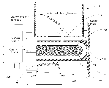
[0052] Referring now to Figure 7, shown is a longitudinal cross-sectional view
of a
heated electrospray ionization source 112 in fluid communication with an ion
inlet 114 of
a FAIM.S 116 including a temperature controller according to an embodiment of
the
instant invention. For simplification, not all electrical connections are
shown. In this
specific and non-limiting example, the FAIMS 116 includes a temperature
controller.
The FAIMS 116 in this non-limiting example is a cylindrical electrode geometry
FAIMS
analyzer with a domed inner electrode. Of course, this non-limiting example is
intended
to encompass other electrode geometries of FAIMS. It is preferred, but not
essential, that
the gas temperature at the source of the curtain gas flow be adjusted so that
the
temperature of the stream of curtain gas that transports the ions into and
through FAIMS
116 remains approximately constant, at least to within a known tolerance
limit, between
the ion inlet 114 and an ion outlet 118. Changes in temperature of the gas
while the ions
CA 02493526 2005-O1-21
Doc. No. 151-24 CA Patent
are being transported through FAIMS 116 results in a loss of the balance
between the
asymmetric waveform and compensation voltage that is needed to transport a
particular
ion. Consider one specific and non-limiting example. If ions enter FAIMS 116
and the
temperature of the gas and the voltages are exactly balanced to transmit an
ion of interest,
the ion of interest drifts parallel to the surfaces of the inner electrode 120
and the outer
electrode 122, being carried by the gas (superimposed with the oscillation
motion caused
by the waveform) to the ion outlet 118. If the temperature of the gas begins
to change,
for example because the electrodes 120 and 122 are warmer than the gas
entering FAIMS
116, then the balanced condition may no longer exist and the ions of interest
that were
being transported begin to drift towards one of the electrodes 120 or 122, and
are lost by
collision with the electrode 120 or 122. It is advantageous, from the point of
view of
efficiency of ion transmission, that the conditions be approximately constant
during the
passage of the ion through FAIMS 116. To this end, a temperature sensor 900 is
provided for sensing a temperature that is based upon a temperature within a
portion of
the FAIMS 116, and for providing an output signal in dependence upon the
sensed
temperature. The temperature controller, which is in communication with the
temperature sensor, receives the output signal and controllably affects the
temperature
within the portion of the FAIMS 116 in dependence thereon. Temperature control
includes any one of adding heat, removing heat or making no change in
dependence upon
a difference between or a sameness of the sensed temperature and the desired
temperature. Non-limiting examples of a temperature sensor include
thermometers,
thermocouples and optical temperature measuring devices such as a fluoroptic
probe.
[0053] In some cases, a change in conditions during passage of an ion through
FAIMS
116 promotes separation of ions with similar properties, and hence enhances
the
resolution of the device. The ions are exposed to conditions that change while
traveling
along the FAIMS analyzer region if, for example, there is a temperature change
in the gas
between the ion inlet and the ion outlet of FAIMS. Creating a temperature
difference
between a first zone of the analyzer region, for instance the beginning of the
ion pathway
between the FAIMS electrodes and a second zone of the analyzer region, for
instance,
further along the length of the ion pathway is difficult to control
accurately, but is an
option encompassed by at least some of the embodiments of the instant
invention. In
16
CA 02493526 2005-O1-21
Doc. No. 151-24 CA Patent
practice, simpler opportunities to promote separation arise through a change
in electrode
geometry (e.g. a dome at the end of the cylindrical inner electrode
constitutes a change in
separation conditions). Other possibilities include a change of electrode
spacing, or a
change of applied voltages that the ion experiences during its passage through
FAIMS.
These changes, if controlled, maintain transmission efficiency, while
enhancing the
separation resolution.
[0054] Control of the curtain gas temperature is beneficial, as discussed
above. It has
also been found to be beneficial to control the temperature of the inner
electrode 120, the
outer electrode 122, and the electrically insulating block 124 that supports
the electrodes.
Still referring to Figure 7, the system includes a temperature controller in
the form of a
suitable structure for introducing a plurality of controlled-temperature flows
of a heat-
exchange fluid. The heat-exchange fluid preferably is gas phase, but
optionally a liquid
phase heat-exchange fluid is used. In the interest of brevity, and for non-
limiting
discussion purposes only, a gas-phase heat-exchange fluid is discussed,
however it is to
be clearly understood that a liquid-phase heat-exchange fluid is also
envisaged for use
with the various embodiments of the instant invention. Because of the high
voltage of the
asymmetric waveform applied to one of the FAIMS electrodes, it is desirable
that the
heat-exchange fluid is an electrically insulating substance and is also
capable of resisting
electrical discharge. Because of the high voltage of the asymmetric waveform
applied to
one of the FAIMS electrodes, the temperature sensor is selected so as not to
interfere with
the ability of the waveform generator to provide the required high voltage
asymmetric
waveform or such that its ability to function is not susceptible to the
electric field.
[0055] Figure 7 illustrates the use of a temperature controller in the form of
a flow of a
heat-exchange fluid (preferably gas phase but optionally liquid phase), which
passes
through a heat-exchange passage 126 within some portion of the inner electrode
120, and
a flow of a heat-exchange fluid (preferably gas phase but optionally liquid
phase) that
passes through a heat-exchange passage 128 within some portion of the
electrically
insulating block 124, so as to controllably add heat to or remove heat from
the FAIMS
system. Although not shown in Figure 7, the temperature controller optionally
includes a
flow of a heat-exchange fluid (preferably gas phase but optionally liquid
phase) through a
17
CA 02493526 2005-O1-21
Doc. No. 151-24 CA Patent
not illustrated heat-exchange passage within a portion of the outer electrode
122. Each
flow of a heat-exchange fluid is adjusted to a pre-selected temperature prior
to delivery to
the corresponding heat exchange area, as shown in Figure 7. The temperature of
each
heat-exchange fluid is adjusted by monitoring the temperatures of each FAIMS
component using a temperature sensor, for example optical thermal sensors,
which
provide feedback relating to the temperature. Each heat-exchange fluid
temperature is
adjusted to maintain the FAIMS component at a constant temperature, and to
support
transmission of the ions through FAIMS under temperature conditions that are
considered
optimal for the ion separation being performed. For example the electrode set
is cooled
(instead of heated) to permit transmission of a thermally labile species.
[0056] Of course, in practice, the heat-exchange fluid is any suitable gas or
liquid.
Optionally, different heat-exchange fluids are provided to the different heat-
exchange
passages 126, 128, etc. Furthermore, the temperature sensor optionally is
selected from
known temperature sensors including but not limited to a thermometer, a
thermocouple,
and optical temperature sensing devices, such as a fluoroptic probe.
[0057] The system in Figure 7 also ensures that the temperature is stabilized
quickly
after a new temperature condition is selected. This minimizes the time that is
lost during
equilibration.
[0058] Numerous temperature controllers for controllably affecting temperature
are
feasible for use with the embodiments of the instant invention. However, not
all of these
temperature controllers are equally practical for use with a FAIMS system. For
example,
the inner electrode 120 of FAIMS 116 in Figure 7 operates at high voltages
that are
applied by the not illustrated asymmetric waveform generator; therefore,
preferably the
selected heat-exchange fluid in heat exchange passage 126 is a sufficiently
good
insulating medium such that electrical leakage current through the heat
exchange-fluid
does not exceed the current-producing capability of the asymmetric waveform
generator
and, in this way, does not degrade the performance of the not illustrated high
voltage
asymmetric waveform generator. In addition, the heat-exchange fluid must
resist electric
discharge. In another example where the design of the waveform generator is
such that
18
CA 02493526 2005-O1-21
Doc. No. 151-24 CA Patent
the application of the waveform on the inner electrode 120 makes the
electrodes a part of
a delicately balanced electronic inductor-capacitor (LC) tuned circuit, the
heating/cooling
process must not upset this balance. For instance, the use of a temperature
controller in
the form of an electronic heater cartridge within the inner electrode 120 is
not practical,
nor desirable, because of the excess distributed capacitance added, and the
additional
opportunities for electric discharge which originate from the electrical wires
and external
power supply that are necessary to operate the heater cartridges. These
arguments also
apply to temperature controllers in the form of electronic cooling cartridges.
That said, a
temperature controller in the form of electronic heater cartridges and
electronic cooling
cartridges certainly are viable options for affecting the temperature of the
outer electrode
122 and./or the electrically insulating block 124 that supports the FAIMS
electrodes. In
this example, the use of a thermocouple as the temperature sensor associated
with the
inner electrode is not desirable for the same reasons discussed above relating
to the
additional opportunities for electric discharge which originates from the
additional wiring
needed for the thermocouple.
[0059] Optionally, a temperature controller including a liquid-phase
coolant/heating
fluid is used, although a leak of the fluid near the opening into the vacuum
chamber of
the not illustrated mass spectrometer may damage the instrument, if a leak of
water (for
example) permits liquid water to enter the vacuum chamber of the not
illustrated mass
spectrometer. Similarly, a leak of a liquid coolant into FAIMS may have
serious
consequences including shorting of the waveform generator power supply. In
contrast,
leaks of a gaseous phase heat/cooling fluid into either the mass spectrometer
or FAIMS
are expected to have less dire consequences. A leak of gas-phase heat-exchange
fluid
into FAIMS, although inconvenient because it is likely to affect the
separation of ions, is
not expected to destroy the instrument.
[0060] Finally, preferably the heating/cooling capacity of the selected heat-
exchange
fluid is high enough to re-adjust the temperature of the FAIMS system after
being set to a
new temperature, at a rate that is useful under typical operating conditions,
and to achieve
a desired temperature for a particular application. Gases typically have much
lower heat
capacities than do liquid-phase mediums. The flow rate and the temperatures of
each
19
CA 02493526 2005-O1-21
Doc. No. 151-24 CA Patent
fluid delivered to FAIMS are typically selected to achieve thermal
stabilization within
about 17 minutes. Since the ion source 112 takes time to stabilize after being
set to
operate at a new temperature, it is advantageous to have FAIMS also stabilize
within the
same time period. Preferably, the temperature controller maintains the
temperature of the
FAIMS within a pre-determined range of values about the desired temperature,
even
under changing temperature conditions external to the FAIMS. To this end, the
temperature sensor 900 is provided for sensing a temperature that is based
upon a
temperature within a FAIMS, and for providing an output signal in dependence
upon the
sensed temperature. The temperature controller is in communication with the
temperature sensor and controllably affects the temperature within the FAIMS
in
response to the output signal of the temperature sensor. By way of non-
limiting
examples, the temperature sensor may use physical, chemical, electrical or
optical means
or a combination thereof to sense a temperature and provide an output signal
in
dependf:nce upon the sensed temperature.
[0061] Prior to evaluation with prototypes, it was unknown whether gas
streams, as
described above, would be suitable for controllably affecting temperature
according to
the embodiments of the instant invention. Only after experimental testing was
it
determined that gases were suitable for this purpose. In test systems, the
electrodes were
operated at temperatures up to 180°C and cooled to temperatures
approaching 0°C. In
one non-limiting example, nitrogen gas was used as the heat exchange fluid. In
particular, for cooling purposes, nitrogen gas was provided from a top portion
of a dewer
flask containing a supply of liquid nitrogen, and for heating purposes the
nitrogen gas
was passed through heater cartridges external to the FAIMS prior to being
passed through
the heat exchanger regions of the FAIMS electrode set. Using nitrogen gas as
described
above supported operation of the FAIMS electrode set at temperatures between
10°C and
120°C.
[0062] It should be noted that temperatures below 0°C are also
envisaged for certain
applications, however, additional precautions are required in order to avoid
condensation
and/or freezing along internal and/or external surfaces of the FAIMS
components. For
instance, preferably the internal and external surfaces of the FAIMS are
maintained in
CA 02493526 2005-O1-21
Doc. No. 151-24 CA Patent
contact 'with dried, ultra-pure gases. Similarly, temperatures well in excess
of I 80°C are
also envisaged, but with judicious selection of the materials that are used to
fabricate the
components of the FAIMS. For instance, one possible material is ceramics.
[0063] Since the FAIMS electrodes are optionally fabricated in many ways,
including
but not limited to, concentric cylinders, two parallel plates (flat or
curved), multiple
stacked parallel plates (flat or curved), spherical and cylindrical electrodes
terminating in
a hemisphere (such as for instance the domed electrodes of Figure 2), one
additional
example of a system for heating/cooling of FAIMS electrodes is considered
here.
[0064] Referring now to Figures 8a-8b, shown is a side-to-side FAIMS device
including an outer electrode 140 that is a rectangular solid having openings
in the top and
bottom (opposite surfaces) thereof for defining the ion inlet 142 and the ion
outlet 144,
respectively. This is known as t:he side-to-side FAIMS geometry, as described
for
example by Guevremont and Purves in WO 01/69216, filed on March 14, 2001, by
Guevremont et al. in WO 03/067236, filed on February 07, 2003, and by
Guevremont et
al. in WO 03/067243 filed on February 07, 2003. Typically the inner electrode
146
extends beyond the end of the outer electrode 140 and thus fits into a not
illustrated
electrically insulating block fixed to the ends of the rectangular outer
electrode 140
(details not shown here). Other ways of securing the inner electrode 146 in
the not
illustrated electrically insulating block may also be envisaged. In all the
embodiments
described above, the inner electrode 146 and the outer electrode 140 are
optionally made
of an electrically conductive material, or one or both of the inner electrode
146 and the
outer electrode 140 are made of nonconductive material having a conductive
material
applied to the outer surface in the case of the inner electrode 146, and to
the inner surface
in the case of the outer electrode 140.
[0065] In the side-to-side FAIMS, a stream of ions that enters the ion inlet
142 divides
approximately equally into two separate streams, each of which passes along an
annular
space 150 between the inner electrode 146 and outer electrode 140, on opposite
sides of
the inner electrode 146. Upon the application of an rf asymmetric potential
waveform to
21
CA 02493526 2005-O1-21
Doc. No. 151-24 CA Patent
one of the electrodes, the annular space 150 acts as the analyzer region where
FAIMS
separation occurs.
[0066] Referring now to Figure 9, shown is a cross sectional view of a heated
electrospray ionization source 200 in fluid communication with an ion inlet
202 of a side-
to-side FAIMS 204 including a temperature controller according to an
embodiment of the
instant invention. The side-to-side FAIMS device 204 is mounted between the
heated
electrospray ionization source 200 and the front plate 206 of the vacuum
chamber of a
not illustrated mass spectrometer. The heated electrospray ionization source
200 shown
at Figure 9 uses a hot gas jet 208 to improve the rate of desolvation of the
electrically
charged droplets produced at the electrospray needle 210. Experimentally this
enables
delivery of liquid samples with a high percentage of water, and permits
enhanced flow
rates of liquid to the electrospray needle 210. Water solvent (over 50% water)
and high
flows of liquid (over 5 uL/min) through typical electrospray needles is
accompanied by
inefficient droplet desolvation. The jet of heated gas 208 shown at Figure 9
is designed
to assist in desolvation in these cases. The temperature of the heated gas is
controlled
and is optimized for particular solvents and/or analyte compounds.
[0067] The hot gas jet 208 shown at Figure 9 impinges on the plate 212 that
separates
the side-to-side FAIMS device 204 from the heated electrospray ionization
source 200.
This plate 212 serves as the curtain plate in that it is held at a voltage
such that ions are
driven away from the ESI needle 210 to the aperture 214 in the plate 212 and
further
driven to the ion inlet 202 of the side-to-side FAIMS 204. The plate 212 is
susceptible to
heating, which in turn causes the temperature of the side-to-side FAIMS device
204 to
drift until equilibrium is reached. It is desirable that the side-to-side
FAIMS 204 be
maintained at a selected temperature within specified tolerances, independent
of the
temperature of the ion source, and/or independent of the temperature of the
hot gas jet
208 being used to desolvate the liquid spray. To this end, a temperature
sensor 900 is
provided for sensing a temperature that is based upon a temperature within a
FAIMS, and
for providing an output signal in dependence upon the sensed temperature. The
temperature controller is in communication with the temperature sensor and
controllably
22
CA 02493526 2005-O1-21
Doc. No. 151-24 CA Patent
affects the temperature within the FAIMS in response to the output signal of
the
temperature sensor.
[0068] Figure 9 also shows that the electrically insulating block 216 of FAIMS
204
optionally includes a heat-exchange passage 218 for providing a flow of a
heating/cooling fluid to control the temperature of the other FAIMS
components.
[0069] Referring now to Figure 10, shown is a longitudinal cross-sectional
view of an
apparatus according to an embodiment of the instant invention and including a
heated
electrospray ionization source in fluid communication with an ion inlet of a
side-to-side
FAIMS with a temperature-controlled inner electrode. Using a temperature
controller, it
is beneficial to controllably affect the temperatures of the three flows of
gas, i) the first
flow of gas to the interface between the ion source and the ion inlet of the
FAIMS device
(the curtain gas), ii) the second flow of gas (or of a liquid) to a heat
exchanger region
inside the inner electrode 220 and iii) the third flow of gas (or of a liquid)
to a heat
exchanger region in the outer electrode 222 and/or the electrically insulating
block 216
supporting the outer electrode 222.
[0070] The temperature of the curtain gas is important because this gas
affects the
heatingicooling, and therefore the temperature, of the region where the ion
source is
adjacent to the FAIMS ion inlet. In addition, the curtain gas divides into a
portion that
enters the side-to-side FAIMS device 204 to carry the ions between the
electrodes and a
portion that flows into the ion source region 200. In one optional approach of
controlling
the temperature of the curtain gas, the conduit 224 for the curtain gas passes
through the
outer electrode 222 and/or through the electrically insulating block 216 prior
to entering
the curtain region. In this way the gas has reached a temperature
approximately equal to
the temperature of one of these FAIMS components.
[0071] Optionally, the temperature of the gases that return from the side-to-
side
FAIMS 204 are monitored, for example using a temperature sensor 900, so as to
sense a
temperature relating to a temperature within the side-to-side FAIMS 204. The
temperature sensor produces an output signal which is communicated to the
temperature
controller. In this case, it is possible to provide feedback control, whereby
the ingoing
23
CA 02493526 2005-O1-21
Doc. No. 151-24 CA Patent
gas temperature is adjusted at the gas supply source by a temperature
controller to
accommodate changes in the heat flows into and out of the FAIMS system, for
example if
the temperature of the hot gas jet used in the ionization source is changed.
Since the
inner electrode 220 is only mounted at its ends in the side-to-side
configuration,
optionally an independent gas flow heat exchange system 226 is provided for
the inner
electrode, separate from that of the electrically insulating block 216, the
block being in
contact with the components of both the heated electrospray ionization source
200 and of
the not illustrated mass spectrometer. It is preferable that the inner
electrode 220 be
maintained at a selected temperature relative to the temperature of the flow
of gas that is
carrying the ions through the side-to-side FAIMS 204. These are optionally
held at equal
temperatures. Figure 10 illustrates a complete system of gas flow and
temperature
control for providing the gases (and/or liquids) at appropriate temperatures
and flow rates
to ensure the stability of the temperature of the components of the FAIMS
device.
[0072] Still referring to Figure 10, the temperature of the inner electrode
220 is
controlled using a flow of heat exchange fluid through the heat exchanger
region 226.
Similarly, the temperature of the outer electrode 222 is controlled by the
temperature of
the electrically insulating block 216 whose temperature is controlled using a
flow of heat
exchange fluid through the heat exchange passage 218 within the electrically
insulating
block 216. Optionally, the temperature of the inner electrode 220 and the
temperature of
the outer electrode 222 are different, thereby forming a gradient in the gas
in the analyzer
region between these two electrodes. The advantages of forming a temperature
gradient
in the FAIMS analyzer region, and the theory thereof are discussed in relation
to Figures
13 to 21.
[0073] Referring now to Figure 1 l, shown is a cross sectional view of the
heated
electrospray ionization source 200 in fluid communication with the side-to-
side FAIMS
204 of Figure 10, but taken in a plane normal to the page of Figure 10.
Accordingly,
Figure 11 illustrates the side-to-side FAIMS device 204 from a second view, in
which the
cylindrical inner electrode is seen from the side (therefore it looks like a
rectangle in
Figure 11). In the instant example, the inner electrode 230 is hollow with a
threaded
insert 232 for ensuring that a flow of a heat exchange fluid (preferably gas
phase but
24
CA 02493526 2005-O1-21
Doc. No. 151-24 CA Patent
optionally liquid phase) makes maximum contact with the inner electrode 230
prior to
returning through a passage 234 drilled through the inner axis of the threaded
insert 232.
The heat exchange fluid (preferably gas phase but optionally liquid phase) is
delivered to
the inner electrode through passages 238 in the electrically insulating block
240 and is
removed from the inner electrode through passage 236. Optionally, one of these
passages
236, 238 includes a heat exchange region prior to or after the heat exchange
fluid has
passed through the inner electrode 230. The flow of gas to the curtain region
242 is
shown to pass through a region 244 that maximizes the contact of the curtain
gas with the
electrically insulating block 240, thus ensuring the curtain gas is
equilibrated to a
temperature dependent on the operating temperature of the FAIMS electrodes
230, 246.
For simplicity, the flow of heat exchange fluid that heats/cools the
electrically insulating
block 240 is not shown.
[0074] Figure 12 illustrates the heating/cooling system of a side-to-side
FAIMS
electrode system in which the outer (electrically conductive) electrode 250 is
fabricated
as a relatively large rectangular block. This design permits direct
heating/cooling of the
outer electrode 250 by incorporating a temperature controller (heat exchange
region 252)
within the body of the outer electrode 250. In practice, for example, this
heat exchange
process occurs through a series of passageways 254 drilled in the body of the
outer
electrode 250 in a direction perpendicular to the cross-section of the
electrodes shown.
Figure 12 also illustrates that the temperature controller optionally includes
a passageway
256 for the curtain gas to pass through a portion of the outer electrode 250,
for the
purposes of moderating the temperature of the curtain gas to be similar to
that of the outer
electrode 250. Further optionally, a heating/cooling flow of a heat exchange
fluid
(preferably gas phase but optionally liquid phase) passes through the inner
electrode 258,
shown in schematic form in Figure 12.
[0075] Still referring to Figure 12, the temperature of the inner electrode
258 is
controlled using a temperature controller including a flow of a heat exchange
fluid
through the heat exchanger within the electrode. Similarly, the temperature of
the outer
electrode is controlled using a temperature controller including a flow of a
heat exchange
fluid through a passageway 254 (part of heat exchanger region 252) within the
outer
CA 02493526 2005-O1-21
Doc. No. 151-24 CA Patent
electrode 250. Optionally, the temperature of the inner electrode 258 and the
temperature
of the outer electrode 250 are different, thereby forming a temperature
gradient in the gas
in the analyzer region between these two electrodes. The advantages of forming
a
temperature gradient in the FAIMS analyzer region, and the theory thereof are
discussed
below.
[0076] The side-to-side FAIMS device illustrated in Figures 8 through 12 is
provided
as a non-limiting example of a FAIMS device for use with the embodiments of
the instant
invention. Of course, other FAIMS electrode geometries are intended to be
encompassed
by the instant invention, including as some non-limiting examples: concentric
cylinder
geometry electrodes with or without a domed inner electrode; flat or curved
parallel plate
geometry electrodes; and spherical electrodes.
[0077] Figure 13 illustrates one possible design of a parallel flat-plate
FAIMS device
that uses a temperature gradient across the analyzer region to affect ion
focusing. The
asymmetric waveform is applied to plate 300 through an electrical coupling 301
to power
supply 302. The asymmetric waveform and the compensation voltage (CV) are
preferably applied to the same plate 300. Although it is possible to apply the
waveform
and CV to the other flat plate 304, this is not preferred since the waveform
and CV
voltages on plate 304 generate unfavorable electric fields between the plate
304 and the
curtain plate 306 and between the plate 304 and the sampler cone 308. These
fields
interfere with the stream of ions that is flowing towards ion inlet 310 and
out of the ion
outlet 312, respectively.
[0078] Referring still to Figure 13 a selected do voltage is applied to flat
plate 304 via
an electrical coupling 313 to a power supply 314. The spacing between plate
304 and
plate 3(10 (the FAIMS electrodes), the applied voltages and the gas pressure
are selected
to be appropriate for ion separation by the FAIMS mechanism in the analyzer
region 326.
As mentioned above, the plate 304 has two openings, an ion inlet 310 and an
ion outlet
312.
[0079] Referring still to Figure 13 a mixture of ions is formed by an
ionization source
316, which in this diagram is illustrated to be an electrospray needle as a
non-limiting
26
CA 02493526 2005-O1-21
Doc. No. 151-24 CA Patent
example of an ionization source suitable for use with the apparatus
illustrated in Figure
13. The ions (of appropriate polarity) in the ion/droplet electrospray plume
318 are
driven toward the curtain plate 306 by the electric field between the
electrospray needle
316 and the curtain plate 306. Some of the ions pass through the curtain plate
orifice
320. A flow of curtain gas 322 is supplied to the curtain region 324 between
the curtain
plate 306 and the flat plate 304. The voltage supplied to the curtain plate
306 via power
supply 334 is used to further direct the ions in the direction of the flat
plate 304. Some of
the ions pass into the ion inlet 310 and are separated in the analyzer region
326 between
the flat plate 304 and the flat plate 300.
[0080] The curtain gas 322 supplied to the curtain region 324, splits into two
flows, the
first exiting through the curtain plate orifice 320 and flowing in a direction
counter-
current to the ions arriving at the curtain plate orifice 320, and the second
flow entering
the FAIMS analyzer region 326 through the ion inlet 310. This second flow is
combined
with an optional carrier gas 328 and this summed gas flow serves to carry the
ions along
the analyzer region 326 to the ion outlet 312. The ion detection system 330 is
preferably
a mass Spectrometer but optionally is an electrometric or optical detection
system, as
some non-limiting examples. The detection system 330 shown in Figure 13
includes a
sampler cone 308 that is in gas-tight connection to the flat plate 304. The
gas and ions
from the analyzer region 326 flow into the sampler cone 308 since the mass
spectrometer
330 is operated at reduced pressure and pulls the ions and gas out of the
analyzer region
through ion outlet 312. Since the mass spectrometer 330 is mounted in gas
tight
connection to the flat plate 304, the flow rate of gas through the analyzer
region 326 is
controlled by the flow rate of gas pulled into the vacuum system of the mass
spectrometer
330 through the orifice 332. The flow rate into the vacuum system of the mass
spectrometer 330 is controlled by the dimensions of the orifice 332 in the
sampler cone
308, and by the composition, pressure and temperature of the gas flowing
through the
analyzer region 326.
[0081] Referring still to Figure 13, a temperature controller including a heat
exchanger
404 is also provided for controlling the temperature of the flat plate 300. A
heat
exchanger fluid 400 is provided to a fluid inlet 402 in the heat exchanger
404. The fluid
27
CA 02493526 2005-O1-21
Doc. No. 151-24 CA Patent
400 is transported through heat exchanger 404 and exits via fluid outlet 406.
A not-
illustrated system pumps the heat exchanger fluid 400, and adds or removes
heat from the
fluid 400, to allow the temperature of the heat exchanger 404 and of the flat
plate 300 to
be selected and maintained within selected tolerances. To this end, a
temperature sensor
900 is provided for sensing a temperature that is based upon a temperature
within the
FAIMS, and for providing an output signal in dependence upon the sensed
temperature.
The temperature controller is in communication with the temperature sensor and
controllably affects the temperature within the FAIMS in response to the
output signal of
the temperature sensor. For clarity in this figure, an optional heat exchange
system for
control of the temperature of plate 304 is not shown.
[0082] As is discussed below in greater detail, setting the flat plate
electrode 304 and
the flat plate electrode 300 to different temperatures, so as to establish a
temperature
gradient in the gas therebetween, results in the establishment of a gradient
in the electric
field, E~N, between the electrode plates. As a consequence of the gradient of
E/N, the ion
focusing mechanism of FAIMS becomes operative. This is a significant advantage
of the
instant invention because in the absence of temperature gradients, the flat
plate geometry
of FAIMS was not previously expected to exhibit ion focusing behavior. As a
result of
the temperature gradient being established, and the associated gradient of
E/N, ions
transmitted at the applied voltage of asymmetric waveform and compensation
voltage are
focused as they travel between the flat plates. This results in increased ion
transmission
efficiency since ion loss through mechanisms of diffusion and space charge ion-
ion
repulsion (as some non-limiting; examples of mechanisms of ion loss) is
minimized.
[0083] Advantageously, the ability to controllably affect the temperature of
each of the
FAIMS electrodes supports a method for separating ions with controllably
variable ion
focusing strength. This method is discussed in conjunction with the following
figures, in
which a series of non-limiting examples is depicted for the purpose of
facilitating a better
understanding the instant invention.
(0084] Figure 14 illustrates (not to scale) an end view of a cylindrical
geometry FAIMS
with inner electrode 500 and outer electrode 501 in concentric arrangement and
a FAIMS
28
CA 02493526 2005-O1-21
Doc. No. 151-24 CA Patent
analyzer region 502 defined by t:he annular space between the inner electrode
500 and the
outer electrode 501. The electric field E/N measured in Townsend (Td) is
defined as
(E/N)x10~~ where E is the electric field in volts/cm and N is the number
density of the
gas (molecules/cc). The electric field E/N was calculated at three different
radial
locations in the analyzer region 502, at about 5%, 50% and 95% of the distance
from the
surface of the inner electrode 500 to the surface of the outer electrode 501.
The spacing
and voltages, and physical dimensions, and conditions of gas pressure and
temperature
are as follows: inner electrode 500 radius = 1 mm; outer electrode 501 radius
= 3 mm;
space 502 between electrodes = 2mm; voltage applied to the inner electrode =
+2500
volts; gas pressure = 760 torr; and, uniform gas temperature = 295 K. In the
region near
the inner electrode 500 the electric field was calculated to be about 83 Td
whereas the
electric field at about 95% of the distance to the outer electrode was 31 Td.
This decrease
in field strength in the space between the electrodes is well known for the
cylindrical
geometry (and spherical geometry, and for several other arrangements of
electrodes
having curved electrode surfaces). The change in electric field E/N is
responsible for the
ion focusing properties that are known to exist in a cylindrical geometry of
FAIMS. Of
course, any operating parameter which gives rise to a non-constant electric
field E/N
supports ion focusing in the FAIMS analyzer region. The ion focusing property
is known
to reduce loss of ions to the walls of FAIMS, and thereby improves ion
transmission
efficiency. Many geometrical arrangements of electrodes produce an electric
field E/N
that varies in strength over a distance, one of the conditions that is
required for ion
focusing. The conditions of asymmetric waveform and the electric field
strengths that are
needed for operation of the FAIMS ion separation mechanism are well known.
When
these conditions of asymmetric waveform and field strengths are applied to an
electrode
geometry wherein the electric field E/N changes in strength in space it is
well known that
the ion focusing mechanism of FAIMS becomes operative. Several practical
embodiments of ion focusing and ion trapping FAIMS have been reported in the
literature, for example Guevrernont and Purves, Rev. Sci. Instrum. 1999, 70,
1370-1383
and Guevremont et al., J. Am. Soc. Mass Spectrometry 2001, 12, 1320-1330 and
in US
patent E~,621,077 (Sept 16, 2003).
29
CA 02493526 2005-O1-21
Doc. No. 151-24 CA Patent
[0085] Figure 15 closely resembles Figure 14, but the calculations of the
field E/N in
Figure 15 are based on a gas temperature that varies approximately linearly
between the
inner and outer electrode. This is a first simplifying approximation to a
condition
wherein the inner electrode 500 and the outer electrode 501 are about 40
degrees Celsius
(40 degrees Celsius equals 40 Kelvin (K)) different from each other, and that
the gas is
equilibrated without turbulence or convective flows so that heat from the hot
electrode
flows uniformly through the gas and is absorbed by the cooler electrode. Other
operating
parameters are identical to those of Figure 14. The spacing and voltages, and
physical
dimensions, and conditions of gas pressure and temperature are as follows:
inner
electrode 500 radius = 1 mm; outer electrode SO1 radius = 3 mm; space 502
between
electrodes = 2mm; voltage applied = +2500 volts; gas pressure = 760 torr. A
temperature
gradient of +20K/mm starting at 275K at the inner electrode 500 exists. In
Figure 15 the
inner electrode 500 is about 40K cooler than the outer electrode 501.
[0086] Still referring to Figure 15, since the temperature of the gas at
various radial
locations in the analyzer region 502 differ, so does the number density N of
the gas.
When the field E/N in Td is calculated at the same locations as shown in
Figure 14, with
all conditions taken to be the same as in Figure 14 with the exception of the
gas
temperature, the electric field values are not identical. The temperature of
the gas has
altered N, and therefore E/N is not identical in Figure 14 and Figure 15. In
Figure 15,
wherein the inner electrode 500 is about 40K cooler than the outer electrode
501, the
electric field near the inner electrode is lower than that in Figure 14.
Similarly the field
E/N near the outer electrode 501 is higher in Figure 15 than in Figure 14.
This
temperature gradient, with inner electrode 500 cooler than outer electrode 501
has the
effect of reducing the gradient of E/N between the inner electrode 500 and the
outer
electrode 501. This reduces the magnitude of the effect of ion focusing when
FAIMS is
in operation. Reduction of the strength of ion focusing is predicted to result
in a wider
distribution of the ion cloud in the region 502, resulting in more rapid loss
of ions
through collisions with the electrodes (lower ion transmission), and is also
predicted to
narrow the peak widths in the scan of the compensation voltage (CV spectrum).
CA 02493526 2005-O1-21
Doc. No. I51-24 CA Patent
[0087] Referring now to Figure 16, shown is a repeat of the calculations of
Figure 15,
except with the direction of the temperature gradient between the inner
electrode 500 and
the outer electrode 501 reversed. Other operating parameters are identical to
those of
Figures 14 and 15. The spacing and voltages, and physical dimensions, and
conditions of
gas pressure and temperature are as follows: inner electrode 500 radius = 1
mm; outer
electrode 501 radius = 3 mm; space 502 between electrodes = 2mm; voltage
applied =
+2500 volts; gas pressure = 760 torn A temperature gradient of -20K/mm
starting at
275K at the inner electrode 500 exists. In Figure 16 the inner electrode 500
is about 40K
hotter than the outer electrode 501. As before, an idealized (as a simplified
first
approximation) condition of an approximately uniform temperature gradient in
the gas
across the space of the analyzer region 502 is assumed. When the number
density of the
gas is calculated for the three locations shown in Figure 16 (corresponding to
the same
radial locations discussed in Figures 14 and 15), the number density is lowest
when the
gas is at: the highest temperature near the inner electrode 500. This gives an
electric field
E/N near the inner electrode 500 that is higher than was shown in Figure 14.
Similarly,
the electric field E/N near the outer electrode in Figure 16 is lower than
that shown in
Figure 14.
[0088] Still referring to Figure 16, by comparison to Figure 14, the change of
the
strength of the electric field E/N between the inner electrode 500 and the
outer electrode
501 is more pronounced when the gas temperature varies from hot near the inner
electrode 500 to cooler near the outer electrode 501 (Figure 16), than when
the
temperature is uniform across the analyzer region 502 (Figure 14). An increase
in the
gradient of the strength of electric field E/N is expected to increase the
effect of ion
focusing in the analyzer region 502. This results in fewer ions being lost to
the walls of
the electrodes, and better ion transmission through FAIMS. The temperature
gradient
shown in Figure 16 augments, or increases, the gradient of E/N inherently
formed within
the cylindrical geometry FAIMS.
[0089] As shown in Figures 14, 15 and 16, the selection of the temperatures of
the
inner electrode 500 and outer electrode 501 is used to affect the performance
of FAIMS.
Of course, in a practical chemical analysis the requirements of transmission
efficiency
31
CA 02493526 2005-O1-21
Doc. No. 151-24 CA Patent
and CV peak widths depend upon the application and the particular type of ion
analysis
being performed. By improper selection of the temperatures of the electrodes,
it is
possible to significantly adversely affect ion transmission. It was discussed
earlier that
preferably the CV of transmission of a selected ion be maintained throughout
the path of
transmission of the selected ion. In one approach, the temperature of one
electrode is
adjusted to be higher than the temperature of the carrier gas, whereas the
temperature of
the other electrode is adjusted to be lower than the temperature of the
carrier gas. By
adjustment of the temperatures, equal heat is provided to the gas by the
higher
temperature electrode as is removed by the lower temperature electrode. Since
no net
heat is added or removed from the gas, the average gas temperature is
maintained
(although regions near the electrodes deviate from this average temperature),
and the CV
of the transmission of the selected ion does not shift. In practice, the
temperatures of the
electrodes are adjusted, and ion transmission monitored, to obtain a desired
degree of ion
transmission and the desired width of the peaks in the CV spectrum that meet
the needs
of the particular chemical analysis application.
[0090] Figures 17 and 18 are comparable to Figures 14 to 16, but with the
cylindrical
FAIMS electrodes of Figures 14 to 16 replaced by parallel flat-plate
electrodes. Since the
electric field between two parallel flat-plates (away from edges) is uniform,
the FAIMS
ion focusing mechanism typical of cylindrical electrode geometry is not
normally
expected to function between parallel flat-plates (away from edges). Referring
now to
Figure 17, the electric field E/N is calculated within the analyzer region 602
at locations
about 5%, 50% and 95% of the distance between a left flat plate 600 and a
right flat plate
601. The conditions of electrode spacing, voltages, gas pressure and
temperature are as
follows: left electrode = flat plate; right electrode = flat plate; space
between electrodes =
2 mm; voltage applied = 2500 volts; pressure = 760 torr; and, uniform gas
temperature =
295K.
[0091] Still referring to Figure 17, the field strength E/N is about 50 Td, at
all points
between the left plate 600 and right plate 601.
32
CA 02493526 2005-O1-21
Doc. No. 151-24 CA Patent
[0092] Figure 18 is similar to Figure 17 except that the temperature of the
left electrode
600 is about 40K hotter than the right electrode 601 and the gas temperature
varies
linearly between these temperatures in the analyzer region 602 between the
left electrode
600 and the right electrode 601. The electric field E/N was calculated at the
same
locations relative to the electrodes as in Figure 17, but since the
temperature of the gas is
not uniform across the analyzer 602, the values of E/N near the left electrode
600 is
higher than near the right electrode 601. This mimics the gradient of E/N
typically found
in the annular region between concentric cylinders, and the gradient of E/N is
suitable for
focusing of ions. This is the first report of a method and apparatus for
focusing of ions in
the space between parallel flat-plate electrodes. The FAIMS mechanism of ion
focusing
in this new case of parallel flat-plates held at differing temperatures (with
a gradient of
gas temperature between the plates) is identical to that previously described
for
cylindrical geometry wherein the gradient of E/N forms simply because of the
electrode
geometry.
[0093] Figure 19 illustrates a comparison between the gradients of electric
field E/N
formed with parallel flat-plates held at differing temperatures, and the
gradients of
electric field E/N formed with concentric cylinders held at uniform
temperature. As
shown at part a) of Figure 19, the left plate 600 is held at 40K hotter than
the right plate
601, and a uniform temperature gradient in the gas is formed across the
analyzer region
602 between the parallel flat-plates. The field strength E/N near the left
plate 600 is
about 53 Td, near the middle is about 50 Td and near the right plate 601 is
about 47 Td.
This corresponds to a gradient of E/N of about 3 Td per mm. If, as shown at
part b) of
Figure 19, cylindrical geometry electrodes are operated at constant
temperature, with the
same voltage and mechanical distances between the electrodes, a change of E/N
of about
4 Td per mm is formed when the inner electrode 605 is about 10 mm radius and
the outer
electrode 606 is about 12 mm radius. The change of E/N per radial distance
decreases as
the radii of the electrodes is increased while maintaining the same spacing
(i.e., as the
curvature of the surfaces of the concentric cylinders begins to decrease and
the surfaces
begin to approximate the equivalently spaced parallel flat plates). The
strength of the ion
focusing effect in FAIMS is known to decrease in strength as the gradient of
E/N
decreases.
33
CA 02493526 2005-O1-21
Doc. No. 151-24 CA Patent
[0094 Preferably, independent control of the temperature of the FAIMS
electrodes is
used to produce a temperature gradient in the gas in the analyzer region
between the
electrodes. Several examples of means for the independent control of the
temperatures of
these electrodes have been shown in Figures 5 (domed electrodes), Figures 10,
11 and 12
(side-to-side FAIMS electrodes) and Figure 13 (flat parallel plate FAIMS).
Optionally,
the temperature controller is for controllably affecting the temperature of
the flow of a
gas that is introduced into the analyzer region of FAIMS. For instance, the
temperature
controller provides a plurality of separate streams of gas, each stream of the
plurality
being adjusted to a different temperature prior to being introduced into the
analyzer
region of FAIMS. The streams are introduced into the analyzer region, absent
turbulence, such that a first gas flow at a first temperature is adjacent a
first electrode and
a second gas flow at a second temperature is adjacent the second electrode.
This is one
non-limiting example of a method of establishing a temperature gradient within
the
FAIMS analyzer region without varying the temperatures of the first and second
FAIMS
electrodes.
[0095] In many cases it is beneficial to maximize the gradient of ElN to
maximize ion
focusing and thereby minimize ion loss to the electrode surfaces. The
combination of
cylindrical (or spherical) geometry with small radii, and the formation of
temperature
gradients (with maximum temperature differences) provides an approach for
increasing
the strength of the FAIMS ion focusing capability.
[0096] Figure 20 illustrates experimental data that was collected using an
apparatus
according to an embodiment of the instant invention. Ions of acetaminophen and
reserpine were generated by electrospray ionization and introduced into a
cylindrical
geometry FAIMS with the side-to-side configuration similar to that shown in
Figures 8a
and 8b. The asymmetric waveform and compensation voltage were applied to the
inner
electrode. Independent flows of gas were passed through flow controllers
including
heating cartridges and subsequently were directed into the inner cylindrical
electrode and
independently into the outer electrode heat exchange regions in a manner
similar to that
shown in Figure 12. The temperature of the gas flowing into the FAIMS
electrodes and
out of the electrodes was monitored. The outer electrode temperature was
measured and
34
CA 02493526 2005-O1-21
Doc. No. 151-24 CA Patent
recorded, and the temperature of the inner electrode was inferred from the
temperature of
the gas exiting from the inner electrode. The compensation voltage was scanned
while
monitoring the acetaminophen ion and monitoring the reserpine ion with a Sciex
API 150
single quadrupole mass spectrometer.
[0097] Referring now to part .~ of Figure 20, shown are experimental results
obtained
with FAIMS operating at room temperature (about 295K). A first trace of the
compensation voltage scan while detecting acetaminophen ion using the mass
spectrometer is shown as trace 801 and a second trace of the compensation
voltage scan
while detecting reserpine ion using the mass spectrometer is shown as trace
802. In the
first trace 801, the acetaminophen ion is transmitted through FAIMS at a
compensation
voltage of approximately +4 volts under ambient conditions of temperature and
pressure,
a pre-determined gas composition, and a predetermined DV. In the second trace,
the
reserpine ion is transmitted through FAIMS at a compensation voltage of
approximately -
8 volts under the same ambient conditions of temperature and pressure, a pre-
determined
gas composition, and a predetermined DV.
[0098] Referring now to part B of Figure 20, shown are experimental results
for a
second experiment at the same gas composition and DV as used in part A, and
conducted
with application of heat to both the inner and the outer FAIMS electrodes. Two
independent flows of gas were each passed through flow controllers and
electrically
powered heating cartridges and subsequently were directed into the inner
cylindrical
electrode heat exchange region and independently into the outer electrode heat
exchange
regions in a manner similar to that shown in Figure 12. The temperature of the
gas
flowing into the FAIMS electrodes and out of the electrodes was monitored. The
outer
electrode temperature was measured and recorded, and the temperature of the
inner
electrode was inferred from the temperature of the gas exiting from the inner
electrode.
The monitored temperatures were both 100°C (373K). The compensation
voltage was
scanned to determine experimentally the compensation voltage at which
acetaminophen
ion and the reserpine ion were transmitted through FAIMS and the resulting ion
signals
are shown as traces 803 and 804, respectively.
CA 02493526 2005-O1-21
Doc. No. 151-24 CA Patent
[0099] The data in Figure 20 illustrates an example in which the selection of
the
temperature of the FAIMS electrode offers the opportunity to adjust the
separation of
compounds of interest. In other words, temperature has unpredictable effects
on the
change of mobility in high electric fields and therefore changes in
temperature are used
beneficially for controlling the separation of ions. The separation of
acetaminophen and
reserpine cannot be done at 373K whereas setting the temperature of the FAIMS
electrodes to room temperature (about 295K) permitted the separation of these
two
compounds.
[00100] Still referring to Figure 20, there are several benefits of
controlling the
temperature of FAIMS. Some of the benefits are widely known and are important
for the
practical application of FAIMS. In a first example, it is beneficial that the
FAIMS
remain at constant temperature so that the CV of transmission of the ion of
interest
remains consistent and reproducible. In a second example, it is beneficial
that the
temperature remain constant when the temperature of other components of the
system are
changed, namely that FAIMS is operating at temperatures (and pressures) that
are not
influenced by adjacent devices. Finally in a third example, it is known in
conventional
drift tube ion mobility spectrometry that elevated temperature minimizes the
formation of
complexes between neutral compounds in the gas and the ion of interest,
thereby
avoiding the widening of peaks that would otherwise occur at lower
temperatures. Some
of these benefits may be applicable to FAIMS while others are not. However in
addition
to the benefits noted above, the effect of temperature has new unforeseen and
unique
consequences in FAIMS. As shown in Figure 20, the separation of acetaminophen
and
reserpine is best done at lower temperature. In FAIMS the temperature provides
a
second-order effect that further modifies the compound-dependent changes in
mobility in
strong electric fields of the ions, in some cases permitting separations at a
second
temperature that did not occur at a first temperature. Referring again to
Figure 20, it
should also be noted that in this case, contrary to expected effects of
temperature in
conventional drift tube ion mobility spectrometry, the performance of FAIMS at
lower
temperatures exceeds that at higher temperatures. Hence, results from
conventional drift
tube ion mobility spectrometry cannot be reasonably used to predict the effect
temperature will have on the capability of FAIMS to achieve a desired
separation.
36
CA 02493526 2005-O1-21
Doc. No. 151-24 CA Patent
[00101] Figure 21 illustrates experimental data that was collected using an
apparatus
according to an embodiment of the instant invention. Ions of acetaminophen
were
generated by electrospray ionization and introduced into a cylindrical
geometry FAIMS
with the side-to-side configuration similar to that shown in Figures 8a and
8b. The
asymmetric waveform and compensation voltage were applied to the inner
electrode.
Independent flows of gas were passed through flow controllers including
heating
cartridges and subsequently were directed into the inner cylindrical electrode
and
independently into the outer electrode heat exchange regions in a manner
similar to that
shown in Figure 12. The temperature of the gas flowing into the FAIMS
electrodes and
out of the electrodes was monitored. The outer electrode temperature was
measured and
recorded, and the temperature of the inner electrode was inferred from the
temperature of
the gas exiting from the inner electrode. The compensation voltage was scanned
while
monitoring the acetaminophen ion with a Sciex API 150 single quadrupole mass
spectrometer.
[00102] Still referring to Figure 21, a first experiment was conducted without
any
heating to FAIMS or to the ionization source, and a first trace of the
compensation
voltage scan while detecting acetaminophen ion by the mass spectrometer is
shown as
trace 700 on Figure 21. In the first experiment, the acetaminophen ion is
transmitted
through FAIMS at a compensation voltage of approximately +4 volts under
ambient
conditions of temperature, pressure, a pre-determined gas composition, and a
predetermined DV.
[00103] Still referring to Figure 21, a second experiment at the same gas
composition
and DV was conducted by application of heat to the outer FAIMS electrode while
allowing the inner electrode to remain near room temperature. The compensation
voltage
was scanned to determine experimentally the compensation voltage at which
acetaminophen was transmitted through FAIMS and the resulting ion signal shown
as
trace 7(11 in Figure 21. Trace 701 was collected while the outer electrode was
approximately 58°C (331K) and the inner electrode near room temperature
(295K). The
peak in trace 701 is narrower than the trace 700 collected without a
temperature
37
CA 02493526 2005-O1-21
Doc. No. I51-24 CA Patent
difference between the inner and outer electrodes, and the signal intensity of
trace 701 is
lower than that of trace 700.
[00104] Referring again to Figure 21, a third experiment at the same gas
composition
and DV was conducted by application of heat to the inner electrode while
allowing the
outer electrode to remain near room temperature. The compensation voltage was
scanned
to detect the compensation voltage at which acetaminophen was transmitted
through
FAIMS and the resulting ion signal is shown as trace 702 in Figure 21. Trace
702 was
collected while the inner electrode was approximately 100°C (373K) and
the outer
electrode near room temperature (295K). The peak in trace 702 is wider than
the trace
700 collected without a temperature difference between the inner and outer
electrodes,
and the signal intensity of trace 702 is higher than that of trace 700.
[00105] The data in Figure 21 illustrate examples in which the selection of
the
temperature of one electrode to be different than the temperature of the other
electrode
offers the opportunity to adjust the peak width in the compensation voltage
scan and the
sensitivity of the measurement of the ion of interest. In other words,
temperature
gradients in the gas between the electrodes beneficially affect the ion
focusing
mechanism of FAIMS and beneficially affect the peak widths and sensitivity as
shown in
Figure :? 1. The user of FAIMS selects the peak width and sensitivity that is
appropriate
for a chemical analysis application, and adjusts the temperature and/or
temperature
gradient of the FAIMS to achieve the specified performance for the
application.
[00106] It is an unexpected benefit of the utilization of a temperature
gradient between
the electrodes that the ion focusing mechanism of FAIMS is operative in
electrode
geometries which were previously unable to provide ion focusing. Although very
few
electrode geometries have been discussed in detail in this document, those
skilled in the
art will be able to apply the concepts of utilization of temperature gradients
to modify
E/N gradients in those geometries that inherently exhibit E/N gradients
(including
cylindrical, and spherical geometries as non-limiting examples). Similarly it
will be
recognized that the skilled worker will readily understand the utilization of
temperature
gradients to generate E/N gradients in those geometrical arrangements of
electrodes that
38
CA 02493526 2005-O1-21
Doc. No. 151-24 CA Patent
previously lacked such an E/N gradient, thereby permitting those geometries to
be used in
FAIMS with the beneficial effects of ion focusing. The skilled worker will
also be able
to strategically apply the concepts of temperature gradients in electrode
geometries which
include both one or more regions lacking inherent gradients of E/N as well as,
elsewhere
in the same geometries, one or more regions that have inherent gradients of
E/N because
of non parallel or curved electrode surfaces in such a way as to beneficially
affect ion
transmission efficiency and ion separation capability of the FAIMS system.
[00107] The apparatus of the instant invention supports a novel approach for
improving
the separation capability of a FAIMS analyzer. As discussed above in reference
to Figure
20, the effect of the temperature within the FAIMS analyzer region on the
capability of
FAIMS to achieve a desired separation cannot be predicted and, hence, must be
determined experimentally.
[00108] Referring now to Figure 22, shown is a simplified flow diagram of a
method of
separating ions according to an embodiment of the instant invention. At step
1000, a
temperature within an analyzer region of a FAIMS device is set to a
predetermined value
for supporting a separation of a subset of ions from an ionized sample. In an
optional
step (not illustrated) the temperature is optimized to obtain one of a pre-
selected degree
of ion transmission, a pre-selected peak width in the CV scan or a pre-
selected degree of
peak separation in the CV scan. At step 1002, using the FAIMS device, the
subset of
ions is separated from the ionized sample.
[00109] Referring now to Figure 23, shown is a simplified flow diagram of
another
method of separating ions according to an embodiment of the instant invention.
At step
1010, a mixture of ions is provided to a FAIMS analyzer to separate a subset
of ions from
the mixture of ions. At step 1012, in addition to the usual operating
parameters of
asymmetric waveform voltage and gas composition, the pressure in the FAIMS
analyzer
region is set to provide a desired separation. At step 1014, in addition to
the operating
parameters of voltages and pressure, the temperature of the FAIMS analyzer
region is set
to provide the desired separation. At step 1016, the compensation voltage (CV)
is set to
provide a subset of ions from the provided mixture. If required, step 1016 is
further
39
CA 02493526 2005-O1-21
Doc. No. 151-24 CA Patent
repeated, again adjusting the compensation voltage to provide further
different subsets of
ions from the original provided mixture of ions.
[00110] Referring now to Figure 24, shown is a simplified flow diagram of
another
method of separating ions according to an embodiment of the instant invention.
At step
1020 a FAIMS analyzer region is provided, the FAIMS analyzer region defined by
a
space between a first electrode surface and a second electrode surface. At
step 1022 an
output signal is provided from a temperature sensor, the output signal
relating to a
temperature within the FAIMS analyzer region. At step 1024 the temperature
within the
FAIMS analyzer region is controllably affected in dependence upon the output
signal, for
providing approximately a predetermined temperature within the analyzer
region.
Providing approximately a predetermined temperature simply means that the
temperature
is adjusted to a predetermined value within known tolerance limits.
[00111] Numerous other embodiments may be envisaged without departing from the
spirit and scope of the invention.