Language selection

Search

Patent 2493661 Summary

Third-party information liability

Some of the information on this Web page has been provided by external sources. The Government of Canada is not responsible for the accuracy, reliability or currency of the information supplied by external sources. Users wishing to rely upon this information should consult directly with the source of the information. Content provided by external sources is not subject to official languages, privacy and accessibility requirements.

Claims and Abstract availability

Any discrepancies in the text and image of the Claims and Abstract are due to differing posting times. Text of the Claims and Abstract are posted:

  • At the time the application is open to public inspection;
  • At the time of issue of the patent (grant).
(12) Patent Application: (11) CA 2493661
(54) English Title: ELECTROCHEMICAL CELLS
(54) French Title: PILES ELECTROCHIMIQUES
Status: Deemed Abandoned and Beyond the Period of Reinstatement - Pending Response to Notice of Disregarded Communication
Bibliographic Data
(51) International Patent Classification (IPC):
  • C02F 1/46 (2006.01)
  • C02F 1/461 (2006.01)
(72) Inventors :
  • CROSS, DAVID EDWARD (United Kingdom)
(73) Owners :
  • SIGMA PRODUCTS LIMITED
  • DAVID CROSS T/A SIGMA CONSULTING
(71) Applicants :
  • SIGMA PRODUCTS LIMITED (United Kingdom)
  • DAVID CROSS T/A SIGMA CONSULTING (United Kingdom)
(74) Agent: GOWLING WLG (CANADA) LLP
(74) Associate agent:
(45) Issued:
(86) PCT Filing Date: 2003-07-21
(87) Open to Public Inspection: 2004-01-29
Examination requested: 2008-07-15
Availability of licence: N/A
Dedicated to the Public: N/A
(25) Language of filing: English

Patent Cooperation Treaty (PCT): Yes
(86) PCT Filing Number: PCT/GB2003/003540
(87) International Publication Number: WO 2004009498
(85) National Entry: 2005-01-21

(30) Application Priority Data:
Application No. Country/Territory Date
0217268.2 (United Kingdom) 2002-07-23

Abstracts

English Abstract


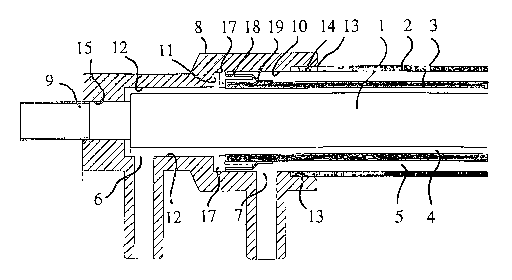
An electrochemical cell has an inner, titanium-rod electrode (1) mounted
coaxially within an outer, titanium-tube electrode (2) with a porous, ceramic
tube (3) mounted coaxially between them to define coaxial, annular passageways
(4,5) for liquid flow in separate streams lengthwise of the cell between
respective pairs of inlet/outlet ports (6, 6; 7, 7). A cup-shape fitting (8)
having a stepped-down internal diameter is clamped onto the rod electrode (1)
at each end of the cell, with the tubular electrode (2) at that end held
tightly sealed in the mouth (14) of the fitting (8). Each end of the ceramic
tube (3) projects into the larger-diameter cavity-part (10) of the fitting (8)
at that end and has a radial flange (17) that provides a sliding seal within
this cavity-part (10) for keeping the inlet/outlet ports (6,7) for the
respective liquid streams at that end, divided off from one another as well as
allowing the ceramic tube (3) limited freedom for longitudinal sliding
relative to the electrodes (1, 2).


French Abstract

La présente invention concerne une pile électrochimique qui présente une électrode interne à tige de titane (1), montée de manière coaxiale à l'intérieur d'une électrode externe à tube de titane (2), présentant un tube poreux en céramique (3) qui est monté de manière coaxiale entre les électrodes afin de définir des passages annulaires (4, 5) pour un écoulement de liquide dans des courants séparés le long de la pile, entre des paires respectives de ports d'entrée/sortie (6, 6; 7, 7). Une pièce de fixation cupuliforme (8), qui présente un diamètre interne décroissant, est serrée sur l'électrode à tige (1) à chaque extrémité de la pile, l'électrode tubulaire (2) à cette extrémité étant maintenue fixement scellée dans le bec (14) de la pièce de fixation (8). Chaque extrémité du tube en céramique (3) fait saillie dans la partie de cavité (10) de plus grand diamètre de la pièce de fixation (8) à cette extrémité et présente un rebord radial (17) qui sert de joint coulissant dans la partie de cavité (10) permettant de maintenir les ports d'entrée/sortie (6, 6; 7, 7) pour les courants de liquide respectifs à cette extrémité, séparés les uns des autres, et permettant de limiter la liberté du tube en céramique (3) concernant un coulissement longitudinal par rapport aux électrodes (1, 2).

Claims

Note: Claims are shown in the official language in which they were submitted.


6
Claims:
1. An electrochemical cell in which an inner
cylindrical electrode extends coaxially within a tube of
ion-permeable material that is mounted coaxially within a
hollow, cylindrical outer electrode to define inner and
outer annular passageways between the respective
electrodes and said tube for liquid-flow lengthwise of
them from one to the other of cup-shape fittings at
either end of the cell, each cup-shape fitting having two
inlet/outlet ports that communicate with the inner and
outer passageways respectively, wherein each cup-shape
fitting defines a cylindrical cavity which has an open-
mouth that is of a diameter to receive a respective end
of the outer electrode for liquid-tight sealing
therewith, said tube projects at each end of the cell
from within the outer electrode into said cavity of the
fitting at that end and has an annular rim for engagement
with an internal cylindrical wall of the cavity for
liquid-tight sealing therewith to separate the inner and
outer passageways from one another within the fitting,
and the inner electrode projects at each end of the cell
from said tube into the cavity of the fitting at that
end.
2. An electrochemical cell according to Claim 1 wherein
the outer electrode is a metal tube.
3. An electrochemical cell according to Claim 1 or
Claim 2 wherein the inner electrode is a metal rod.
4. An electrochemical cell according to any one of
Claims 1 to 3 wherein the particular one of the
electrodes that is to act as the cathode of the cell, is
of titanium or stainless steel.

7
5. An electrochemical cell according to any one of
Claims 1 to 4 wherein the particular one of the
electrodes that is to act as the anode of the cell is of
titanium.
6. An electrochemical cell according to Claim 5 wherein
the anode electrode has a coating that acts as a catalyst
in the electrochemical operation of the cell.
7. An electrochemical cell according to Claim 6 wherein
the coating of the anode electrode is of ruthenium and
iridium oxides.
8. An electrochemical cell according to any one of
Claims 1 to 7 wherein the ion-permeable tube is of a
porous ceramic material.
9. An electrochemical cell according to Claim 8 wherein
the ceramic material is composed of aluminium, zirconium
and yttrium oxides.
10. An electrochemical cell according to any one of
Claims 1 to 9 wherein the annular rim at each end of the
cell is slidable within the cavity of the fitting at that
end to enable sliding of the ion-permeable tube relative
to the inner and outer electrodes.
11. An electrochemical cell according to Claim 10
wherein the annular rim at each end of the cell comprises
a flange of a member that is sealed or otherwise secured
to the ion-permeable tube at that end.
12. An electrochemical cell according to Claim 10 or
Claim 11 wherein the extent to which the ion-permeable
tube can slide relative to the inner and outer electrodes
is limited by abutment within the cavity at each end of
the cell.

8
13. An electrochemical cell according to any one of
Claims 1 to 12 wherein the cavity of each cup-shape
fitting has a stepped internal diameter for defining a
first cavity-part leading from the open mouth and a
second cavity-part of smaller diameter opening from the
first cavity-part.
14. An electrochemical cell according to Claim 13
wherein the ion-permeable tube projects at each end of
the cell from within the outer electrode into the first
cavity-part of the fitting at that end to have its
annular rim engage with the internal cylindrical wall of
the first cavity-part, and the inlet/outlet ports of each
fitting open into/from the first and second cavity-parts
respectively.

Description

Note: Descriptions are shown in the official language in which they were submitted.


CA 02493661 2005-O1-21
WO 2004/009498 PCT/GB2003/003540
Eleatrochemiaal Cells
This invention relates to electrochemical cells.
The invention is particularly, though not exclusively,
concerned with electrochemical cells of the kind used for
purification of water and the production of disinfecting
aqueous solutions. Electrochemical cells of this kind
have been proposed in which an ion-permeable, ceramic
membrane is interposed between coaxial electrodes, and it
is one of the object of the present invention to provide
an improved form of such a cell.
According to the present invention there is provided an
electrochemical cell in which an inner cylindrical
electrode extends coaxially within a tube of ion-
permeable material that is mounted coaxially within a
hollow, cylindrical outer electrode to define inner and
outer annular passageways between the respective
electrodes and said tube for liquid-flow-lengthwise of
them from one to the other of cup-shape fittings at
either end of the cell, each cup-shape fitting having two
inlet/outlet ports that communicate with the inner and
outer passageways respectively, wherein each cup-shape
fitting defines a cylindrical cavity which has an open-
mouth that is of a diameter to receive a respective end
of the outer electrode for liquid-tight sealing
therewith, said tube projects at each end of the cell
from within the outer electrode into said cavity of the
fitting at that end and has an annular rim for engagement
with an internal cylindrical wall of the cavity for
liquid-tight sealing therewith to separate the inner and
outer passageways from one another within the fitting,
and the inner electrode projects at each end of the cell
from said tube into the cavity of the fitting at that
end.

CA 02493661 2005-O1-21
WO 2004/009498 PCT/GB2003/003540
2
The outer electrode may be a metal tube, and the inner
electrode a metal rod. The metal involved in each case
may be titanium, however, where the electrode is for use
as the cathode of the cell it may, as an alternative, be
of stainless steel. Where the electrode is for use as
the anode, it may have a coating (for example, of
ruthenium and iridium oxides) that acts as a catalyst in
the electrochemical operation of the cell.
The ion-permeable tube may be porous and in this respect
may be of a ceramic material, for example composed of
aluminium, zirconium and yttrium oxides. The annular rim
at each end of the cell may be slidable within the cavity
of the fitting at that end to enable sliding of the ion-
permeable tube relative to the inner and outer
electrodes, and may be provided by a flange of a member
that is sealed or otherwise secured to the ion-permeable
tube at that end. The extent to which the ion-permeable
tube can slide relative to the inner and outer electrodes
may be limited by abutment within the cavity at each end
of the cell. The abutment may be with a part (for
example, a pin or annular rim) that projects laterally
into the cavity, or of a longitudinal projection from the
tube-end with the bottom of the cavity, or of a
longitudinal projection from the bottom of the cavity
with the tube-end.
The cavity of each cup-shape fitting may have a stepped
internal diameter for defining a first cavity-part
leading from the open mouth and a second cavity-part of
smaller diameter opening from the first cavity-part. In
these circumstances, the ion-permeable tube may project
at each end of the cell from within the outer electrode
into the first cavity-part of the fitting at that end to
have its annular rim engage with the internal cylindrical
wall of the first cavity-part. The inlet/outlet ports of

CA 02493661 2005-O1-21
WO 2004/009498 PCT/GB2003/003540
3
each fitting may open into/from the first and second
cavity-parts respectively.
An electrochemical cell in accordance with the present
invention will now be described, by way of example, with
reference to the accompanying drawing, in which:
Figure 1 is a part sectional side-elevation of the
electrochemical cell according to the invention; and
Figure 2 is an enlarged sectional side-elevation of one
end of the electrochemical cell of Figure 1.
Referring to Figures 1 and 2, the inner and outer
electrodes of the electrochemical cell are formed by a
coaxial rod 1 and tube 2 respectively. The rod 1 and
tube 2 are of titanium and the inside surface of the tube
2, which is to act as the anode, is coated with ruthenium
and iridium oxides that act as a catalyst in the
electrochemical operation of the cell. A porous ceramic
tube 3 composed of aluminium, zirconium and yttrium
oxides, is supported coaxially between the rod 1 and tube
2 to provide an intermediate ion-permeable membrane for
separating the products derived electrochemically at the
two electrodes. More particularly, the tube 3 divides
the space between the rod 1 and tube 2 into two coaxial,
annular passageways 4 and 5 for liquid-flow lengthwise of
the electrodes formed by the rod 1 and tube 2.
The passageways 4 and 5 terminate at either end of the
cell in sideways-extended inlet/outlet ports 6 and 7,
respectively, of individual one-piece plastics fittings 8
(for example, of polypropylene) that are retained on
opposite ends 9 of the rod 1. Each fitting 8 is of cup-
shape with a stepped internal diameter that defines a
first cylindrical cavity-part 10 into/from which the port
7 opens, and which leads via an annular end-face 11

CA 02493661 2005-O1-21
WO 2004/009498 PCT/GB2003/003540
4
(Figure 2) into a second cylindrical cavity-part 12 of
smaller diameter into/from which the port 6 opens. The
ends 13 of the tube 2 are lightly machined externally
over a short length (for example, 5 mm) so as to enable
them to be received and provide liquid-tight sealing, in
recessed mouths 14 (Figure 2) of the cavity-parts 10 of
the fittings 8.
The rod 1, on the other hand, extends axially through
both cavity-parts 10 and 12 of each fitting 8, and has
ends 9 of reduced diameter. The end 9 within each
fitting 8 projects from the cavity-part 12 into and
through a bore 15 of the fitting 8. It is a liquid-tight
interference fit within the bore 15 (it may be lightly
machined over a length of, for example, 5 mm, to ensure a
constant diameter for the purpose), and is screw-threaded
to receive a nut 16 (only one shown, in Figure 1) where
it projects from the fitting 8. The nuts 16 are
tightened to clamp the fittings 8 firmly onto the two
ends 13 of the tube 2 and hold them to the rod 1 with the
rod 1 and tube 2 coaxial with one another.
The tube 3, which projects beyond the ends 13 of the tube
2 within the cavity-part 10, has a radial rim or flange
17 (Figure 2) at each end. Each flange 17 is part of a
plastics tubular moulding 18 which is retained on the
tube 3 by a plastics sleeve 19 that is heat-shrunk onto
the respective end of the tube 3; the dimensioning of the
moulding 18 allows for manufacturing tolerances in tube-
diameter. The flange 17 provides a liquid-tight, sliding
fit within the internal cylindrical wall of the
respective cavity-part 10, separating the passageways 4
and 5 from one another within the fitting 8 at that end.
More especially, the extent of projection of the tube 3
beyond the end 13 of the tube 2 within each fitting 8
ensures that the flange 17 is located deeper within the

CA 02493661 2005-O1-21
WO 2004/009498 PCT/GB2003/003540
cavity-part 10 than the port 7 so that it maintains
appropriate separation of the port 7 from the cavity-part
12 and port 6. The integrity of this separation is
maintained since the freedom of the tube 3 to slide
5 relative to the tube 2 is limited to a small distance
(for example, 1 to 2 mm) by the walls 11 at both ends of
the cell. However, the freedom for sliding ensures that
the clamping forces exerted by the nuts 16 clamping the
fittings 8 to the ends 13 of the tube 2 and holding them
on the ends 9 of the rod 1, are not exerted on the tube
3. The fact that the somewhat-fragile, ceramic tube 3 is
not subject to any clamping force avoids the need to
cushion it resiliently.
The attachment of the mouldings 18 to the tube 3 may be
by adhesive instead of the heat-shrunk sleeves 19, or by
bonding them on by heating the ends of the tube 3 so that
the plastics is partially melted as the mouldings 18 are
pushed on.
The form of construction of the electrochemical cell
described above, has significant advantages of simplicity
and economy in that the number of components is reduced
as compared with earlier forms, and the extent of
machining required is light and limited to the ends 9 of
the rod 1 and the ends 13 of the tube 2. Moreover, stock
material may be used for the electrodes (for example
seam-welded tubing may be used for the tube 2), and the
porous ceramic tube 3, which for example, may have a
porosity between 50% and 70% with a pore size of between
0.3 and 0.5 microns, is not required to withstand
compressional forces or satisfy tight dimensional
tolerance-limits. The flanges 17 of the mouldings 18
attached to the ends of the tube 3 provide both the
sliding freedom and the liquid-tight sealing required, in
a simple manner without any strict dimensional
requirement on tube-diameter.

Representative Drawing
A single figure which represents the drawing illustrating the invention.
Administrative Status

2024-08-01:As part of the Next Generation Patents (NGP) transition, the Canadian Patents Database (CPD) now contains a more detailed Event History, which replicates the Event Log of our new back-office solution.

Please note that "Inactive:" events refers to events no longer in use in our new back-office solution.

For a clearer understanding of the status of the application/patent presented on this page, the site Disclaimer , as well as the definitions for Patent , Event History , Maintenance Fee  and Payment History  should be consulted.

Event History

Description Date
Time Limit for Reversal Expired 2012-07-23
Application Not Reinstated by Deadline 2012-07-23
Deemed Abandoned - Conditions for Grant Determined Not Compliant 2011-10-07
Deemed Abandoned - Failure to Respond to Maintenance Fee Notice 2011-07-21
Notice of Allowance is Issued 2011-04-07
Letter Sent 2011-04-07
Notice of Allowance is Issued 2011-04-07
Inactive: Approved for allowance (AFA) 2011-03-30
Amendment Received - Voluntary Amendment 2010-11-10
Letter Sent 2010-08-16
Inactive: Single transfer 2010-07-14
Inactive: S.30(2) Rules - Examiner requisition 2010-05-10
Amendment Received - Voluntary Amendment 2008-10-30
Inactive: Delete abandonment 2008-09-16
Letter Sent 2008-09-16
All Requirements for Examination Determined Compliant 2008-07-15
Request for Examination Requirements Determined Compliant 2008-07-15
Request for Examination Received 2008-07-15
Inactive: Abandoned - No reply to Office letter 2007-04-24
Letter Sent 2006-11-15
Revocation of Agent Requirements Determined Compliant 2006-10-26
Appointment of Agent Requirements Determined Compliant 2006-10-26
Inactive: Correspondence - Transfer 2006-10-23
Revocation of Agent Request 2006-10-20
Appointment of Agent Request 2006-10-20
Letter Sent 2006-10-04
Inactive: Multiple transfers 2006-09-06
Inactive: Single transfer 2006-08-17
Revocation of Agent Requirements Determined Compliant 2006-06-30
Inactive: Office letter 2006-06-30
Appointment of Agent Requirements Determined Compliant 2006-06-30
Revocation of Agent Request 2006-06-19
Appointment of Agent Request 2006-06-19
Extension of Time for Taking Action Requirements Determined Compliant 2006-05-10
Letter Sent 2006-05-10
Inactive: Extension of time for transfer 2006-04-24
Inactive: Courtesy letter - Evidence 2005-03-29
Inactive: Cover page published 2005-03-24
Inactive: Notice - National entry - No RFE 2005-03-22
Application Received - PCT 2005-02-21
National Entry Requirements Determined Compliant 2005-01-21
Application Published (Open to Public Inspection) 2004-01-29

Abandonment History

Abandonment Date Reason Reinstatement Date
2011-10-07
2011-07-21

Maintenance Fee

The last payment was received on 2010-07-20

Note : If the full payment has not been received on or before the date indicated, a further fee may be required which may be one of the following

  • the reinstatement fee;
  • the late payment fee; or
  • additional fee to reverse deemed expiry.

Please refer to the CIPO Patent Fees web page to see all current fee amounts.

Owners on Record

Note: Records showing the ownership history in alphabetical order.

Current Owners on Record
SIGMA PRODUCTS LIMITED
DAVID CROSS T/A SIGMA CONSULTING
Past Owners on Record
DAVID EDWARD CROSS
Past Owners that do not appear in the "Owners on Record" listing will appear in other documentation within the application.
Documents

To view selected files, please enter reCAPTCHA code :


To view images, click a link in the Document Description column. To download the documents, select one or more checkboxes in the first column and then click the "Download Selected in PDF format (Zip Archive)" or the "Download Selected as Single PDF" button.

List of published and non-published patent-specific documents on the CPD .

If you have any difficulty accessing content, you can call the Client Service Centre at 1-866-997-1936 or send them an e-mail at CIPO Client Service Centre.


Document
Description 
Date
(yyyy-mm-dd) 
Number of pages   Size of Image (KB) 
Claims 2010-11-10 3 100
Abstract 2005-01-21 1 73
Claims 2005-01-21 3 99
Drawings 2005-01-21 1 30
Description 2005-01-21 5 240
Representative drawing 2005-01-21 1 20
Cover Page 2005-03-24 1 56
Description 2010-11-10 5 243
Reminder of maintenance fee due 2005-03-22 1 111
Notice of National Entry 2005-03-22 1 193
Request for evidence or missing transfer 2006-01-24 1 100
Courtesy - Certificate of registration (related document(s)) 2006-10-04 1 105
Reminder - Request for Examination 2008-03-26 1 119
Acknowledgement of Request for Examination 2008-09-16 1 176
Courtesy - Certificate of registration (related document(s)) 2010-08-16 1 103
Commissioner's Notice - Application Found Allowable 2011-04-07 1 163
Courtesy - Certificate of registration (related document(s)) 2010-08-16 1 104
Courtesy - Abandonment Letter (Maintenance Fee) 2011-09-15 1 173
Courtesy - Abandonment Letter (NOA) 2012-01-03 1 165
PCT 2005-01-21 4 176
Correspondence 2005-03-22 1 26
Fees 2005-07-21 1 28
Correspondence 2006-04-24 1 44
Correspondence 2006-05-10 1 15
Fees 2006-04-27 1 37
Correspondence 2006-06-19 1 29
Correspondence 2006-06-30 1 14
Correspondence 2006-10-20 1 32
Correspondence 2006-11-15 1 13
Fees 2008-07-08 1 42
Fees 2009-07-13 1 40
Fees 2010-07-20 1 41
Correspondence 2011-04-07 1 53