Note: Descriptions are shown in the official language in which they were submitted.
CA 02494196 2005-02-09
WO 2004/025763 PCT/DE2003/002603
CONTROL OF A FLUID FLOW IN AN ELECTROCHEMICAL CELL
The invention relates to an electrochemical cell, in
particular a proton exchange membrane fuel cell (PEM
fuel cell) or an electrolysis cell, according to the
precharacterizing clause of patent claim 1.
In an electrolysis cell with a cathode and an anode,
eiectricai energy is converted into chemical energy.
Electrical current is used to break down a chemical
compound by an ionic discharge. When an external
voltage is applied, electrons are absorbed by the ions
at the cathode within a reduction process. Electrons
are given off by the ions at the anode within an
oxidation process. The electrolysis cell is
constructed in such a way that reduction and oxidation
take place separately from one another.
Fuel cells are galvanic elements with a positive
terminal and a negative terminal, or with a cathode and
an anode, which convert chemical energy into electrical
energy. Electrodes are used for this purpose,
interacting with an electrolyte and preferably a
catalyst. A reduction takes place at the positive
terminal, resulting in an electron deficiency. An
oxidation takes place at the negative terminal,
resulting in an electron excess. The electrochemical
processes take place in the fuel cell as soon as an
external circuit is connected.
A typical construction of a fuel cell is shown in DE
100 47 248 A1. The fuel cell comprises a cathode
electrode, an anode electrode and a matrix, which
together form a membrane electrode assembly (MEA). The
cathode electrode and the anode electrode respectively
comprise an electrically conducting body which serves
as a carrier for a catalyst material. The matrix is
arranged between the cathode electrode and the anode
CA 02494196 2005-02-09
WO 2004/025763 PCT/DE2003/002603
- 2 -
electrode and serves as a carrier for an electrolyte.
A number of fuel cells are stacked on one another with
separator plates interposed. The supply, circulation
and discharge of oxidants, reductants, reactants and
coolants takes place by means of a system of channels,
which are produced by the separator plates. For each
liquid or gaseous operating material, supply collecting
channels, distribution channels and discharge
collecting channels are provided in the fuel cell
stacks, separated from one another by sealing means.
The supply collecting channels and discharge collecting
channels are referred to in English-speaking regions as
ports. The cells of a stack are supplied with an
oxidant fluid, a reactant fluid and a coolant in
parallel by means of at least one supply collecting
channel. The reaction products, excess reactant and
oxidant fluid and heated coolant are removed from the
cells by means of at least one discharge collecting
channel out of the stack. The distribution channels
form a connection between the supply collecting channel
and discharge collecting channel and the individual
active channels of a fuel cell. The fuel cells may be
connected in series to increase the voltage. The
stacks are closed off by end plates and accommodated in
a housing, the positive terminal and negative terminal
being led to the outside to a consumer unit.
In Japanese patent application JP 60-041769 A there is
a description of a fuel cell system in which a fuel
cell stack is surrounded by a thermal insulator. For
heat dissipation, the fuel cell stack is surrounded by
a metallic body with good heat conduction. U-shaped
bimetal bodies are fastened to the body. If the
temperature in the fuel cell stack exceeds a
predetermined temperature, the bimetal bodies are
deformed and come into contact with radiator plates, so
that a heat transfer takes place from the heat-
conducting metallic body of the fuel cell stack via the
CA 02494196 2005-02-09
WO 2004/025763 PCT/DE2003/002603
- 3 -
bimetal bodies to the radiator plates. The arrangement
is voluminous and the heat dissipation by means of a
mechanical contact is less than satisfactory.
In the case of the liquid fuel cell system shown in
Japanese patent application JP 61-058173 A, a fuel cell
stack is flowed around by cooling air of a fan. The
cooling air flow can be controlled by means of fins
which can be pivoted by a coupling rod in the cooling
air path. The coupling rod is actuated by a bimetal
element, which is in thermal contact with anolyte. If
there are changes in the temperature of the anolyte,
the bimetal element is deformed, so that the fins open
the cooling air path more or less . The cooling system
is arranged on the outside of a fuel cell stack and
thereby increases the overall size of a fuel cell
system. The cooling system is unable to compensate for
temperature inhomogeneities within a fuel cell stack.
Only the overall cell temperature is controlled in each
case.
Furthermore, there are known solutions which use a
fluid-dynamic flow of a cooling air flow onto a fuel
cell stack. In the case of the solution according to
Japanese patent application JP 58-100372 A, the flow
resistance of the cooling air is reduced by special
shaping of a flowing-in region. In the Japanese patent
application JP 58-017964 A, a uniform distribution of
cooling air onto fuel cells by air baffles is
described. In Japanese patent application JP 1185871
A, a special flow guide for cooling air is shown.
In the case of all these solutions, it is in each case
attempted to shape the cooling air flow in such a way
that the temperature of the individual cells is
optimally controlled, without however adapting the
cooling flow to the local requirements.
CA 02494196 2005-02-09
WO 2004/025763 PCT/DE2003/002603
- 4 -
The object of the invention is to develop an
electrochemical cell which has improved efficiency as a
result of improved temperature or moisture distribution
and/or reactant distribution within the cell.
The object is achieved by an electrochemical cell which
has the features as claimed in claim 1. Advantageous
configurations are provided by the subclaims.
The invention allows an open-loop or close-loop control
of fluid flows in the region of an individual cell.
The use of at least one element that changes the flow
cross section within at least one channel allows
setting of the desired temperature distribution or
moisture distribution, which depends on the cooling
medium and operating state of the cell.
A major advantage of the arrangement according to the
invention is that each channel can be individually
controlled, i.e. a variation of the pressure loss in
the individual channels brings about a variation of the
volumetric flows of the individual channels to and from
which gas is supplied and removed jointly by means of
collecting and distribution channels. A homogenization
of the temperature or moisture between the channels is
brought about, if a homogeneous temperature or moisture
distribution is desired. If in the case of more
complex fuel cell systems a specific temperature or
moisture profile is desired, this can be achieved with
a corresponding arrangement of the elements that change
the flow cross sections.
One of the reasons for an unequal temperature
distribution in a fuel cell is an inhomogeneous heat
output. For example, the heat given off to the
surroundings in the case of the outer cells of a fuel
cell stack is greater than in the case of cells lying
on the inside. In particular in the case of air
CA 02494196 2005-02-09
WO 2004/025763 PCT/DE2003/002603
- 5 -
cooling, a non-uniform heat output is obtained by
heating up the cooling fluid. Furthermore, the
reactions within a cell do not take place to the same
extent everywhere, so that the sources of heat are
unequally distributed. The reactions depend among
other things on the local temperature, the local
partial pressures and the local moisture.
With the elements that change the flow cross sections,
such as bimetal strips for example, the coolant flow in
each cooling channel can be controlled. This produces
an optimized temperature distribution.
Furthermore, the elements that change the flow cross
section can be used for open-loop or close-loop control
of the local gas composition by influencing the gas
flows. For example, bimetal strips may be provided in
the fluid channels of one or both reaction gases. If
the fluid channels are connected to one another, a gas
exchange can take place between the channels. As a
result, locally increased cell reactions and locally
higher temperatures are achieved. Higher temperatures
bring about a reduction in the cross section of the gas
channels by the bimetal strips, which has the
consequence that fewer reaction gases are present
locally in this region of the cell and the gas flow
increases in other regions. The decrease in the gas
flow has the effect of reducing the cell reaction, with
an intensification of the reactions in the regions
where the supply is greater. A uniform reaction
distribution is obtained in this way.
In a variant of the invention, the desired reaction
distribution can be set by an arrangement of bimetal
elements and connections between the gas channels. For
this purpose, a flow field for a fluid can be divided
into various regions, with a communication of fluids
over different regions being possible. The fluid
CA 02494196 2005-02-09
WO 2004/025763 PCT/DE2003/002603
- 6 -
channels in the regions may lie parallel to one
another, the elements for changing the cross sections
of the channels advantageously being integrated in
downstream regions.
A further possibility of locally controlling a cooling
air flow and reaction gas flows is provided by the use
of materials or components which change their volume or
their shape in dependence on moisture. Depending on
the reaction partners, in the case of a fuel cell a
phase change occurs, i.e. liquid water may be produced,
on the cathode side in the path of the gas flow between
the inlet and the outlet of a channel. The amount of
water occurring is dependent on the reaction, since the
water is a reaction product. If the said materials or
components are used in such a way that they reduce the
channel cross sections in dependence on the moisture,
the same effect as with the use of bimetal strips can
be achieved in this way.
In the case of control of the local heat, bimetal
strips may be used in the channels on the anode side
and cathode side and in the coolant channels. In the
case of moisture-dependent control, the cross-section-
changing materials or components are incorporated
directly in the cathode channels. If the anode fluid
flow and/or the cooling fluid flow are also to be
controlled moisture-dependently, the moisture in the
cathode fluid flow must be recorded, in order to
achieve a change in channel cross section on the anode
side or cooling fluid side.
The invention is to be explained in more detail below
on the basis of examplary embodiments. In the drawing:
Figure 1 shows a cooling channel of a fuel cell
with a bimetal platelet arranged on
CA 02494196 2005-02-09
WO 2004/025763 PCT/DE2003/002603
the channel base, in the case of a low
cooling fluid temperature,
Figure 2 shows the cooling channel that is
shown Figure 1 in the case of a high
cooling fluid temperature,
Figure 3 shows a cooling channel of a fuel cell
with a bimetai platelet integrated on
the channel base, in the case of a low
cooling fluid temperature,
Figure 4 shows the cooling channel that is
shown in Figure 3, in the case of a
high cooling fluid temperature,
Figure 5 shows a cooling channel of a fuel cell
with a multiplicity of bimetal
platelets arranged on the channel
base, in the case of a high cooling
fluid temperature,
Figure 6 shows the cooling channel that is
shown in Figure 5, in the case of a
low cooling fluid temperature,
Figure 7 shows a cathode channel of a fuel cell
with moisture-dependent swelling
bodies in plan view, in the case of a
dry cathode fluid flow,
Figure 8 shows the cathode channel that is
shown in Figure 7 in the case of a
moist cathode fluid flow,
Figures 9 and 10 show a cathode channel of a fuel cell
with moisture-dependent swelling
bodies in plan view between two fluid
CA 02494196 2005-02-09
WO 2004/025763 PCT/DE2003/002603
_ g _
channels, in the case of two different
temperatures of a cooling fluid, and
Figures 11-13 show various arrangements of bimetal
elements in the flow field of a
cooling fluid in a separator plate.
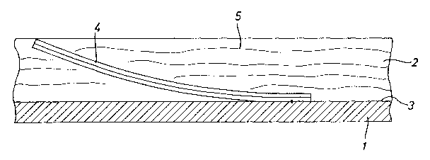
Figures 1 and 2 show a detail from a separator plate 1
of a fuel cell with a rectangular cooling channel 2.
Fastened to the channel base 3 at one end is a likewise
rectangular bimetal platelet 4. The bimetal platelet 4
is essentially of the same width as the cooling channel
2, the width extending perpendicularly in relation to
the plane of the drawing. A cooling fluid 5 circulates
in the cooling channel 2. If the cooling fluid 5 is at
too low a temperature for the operation of the fuel
cell, the bimetal platelet 4 bends up, so that the flow
cross section of the cooling channel 2 is reduced. In
the extreme case, the bimetal platelet 4 bends up to
such an extent that, as shown in Figure 1, it closes
the cooling channel 2 completely. If the cooling fluid
5 does not flow, or only a little, the cooling fluid 5
is heated up by the process taking place in the fuel
cell. As a result, the bimetal platelet 4 bends with
its free end in the direction of the channel base 3 and
increases the flow cross section. The cooling fluid 5
can flow in the indicated direction 6 without great
resistance.
In the description which follows, the same reference
numerals of elements already described are used for
elements with an equivalent function.
Figures 3 and 4 show a detail from a separator plate 1
of a fuel cell with a rectangular cooling channel 2.
On the channel base 3 there is a tongue-shaped notched
portion 7, which is freely movable at one end. Over
the length, the notched portion 7 is connected on the
CA 02494196 2005-02-09
WO 2004/025763 PCT/DE2003/002603
- 9 -
channel side to a metallic, rectangular platelet 8.
The platelet 8 has a coefficient of thermal expansion
that is different from the material of the notched
portion 7, so that the notched portion 7 and the
platelet 8 form a bimetal element. In the case of cool
cooling fluid 5, the notched portion 7 together with
the platelet 8 bends away from the channel base 3, as
represented in Figure 3, and reduces the flow cross
section. Figure 4 shows the state when the cooling
fluid 5 is heated up. The notched portion 7 together
with the platelet 8 returns into the channel base 3, so
that virtually the entire flow cross section is
cleared.
Figures 5 and 6 show a detail from a separator plate 1
of a fuel cell with a rectangular cooling channel 2. A
multiplicity of rectangular bimetal platelets 9-14 are
respectively fastened at one end to the channel base 3.
The fastening ends of the bimetal platelets 9-14 point
in the same direction. The bimetal platelets 9-14 may
be essentially of the same width as the cooling channel
2 or a number of such bimetal platelets 9-14 may lie
next to one another over the width of the cooling
channel 2. The lengths L of the bimetal platelets 9-14
are significantly smaller in comparison with the height
H of the cooling channel 2. Figure 5 shows the state
of the bimetal platelets 9-14 when the cooling fluid 5
is too warm. On account of the high temperature of the
cooling fluid 5, the bimetal platelets 9-14 are raised.
In this state, the raised bimetal platelets 9-14
increase the effective heat-dissipating surface area of
the channel base 3. The raised bimetal platelets 9-14
increase the roughness of the walls and thereby improve
the heat transfer into the material of the separator
plate 1. As a result of the small length of the
bimetal platelets 9-14, the flow cross section of the
cooling channel 2 is reduced only insignificantly.
Apart from on the channel base 3, the bimetal platelets
CA 02494196 2005-02-09
WO 2004/025763 PCT/DE2003/002603
- 10 -
9-14 may of course also be arranged on the other
channel walls of the cooling channel 2. In the case of
a low temperature of the cooling fluid 5, the bimetal
platelets 9-14 lie themselves against the channel base
3, as shown in Figure 6, whereby the contact area with
the cooling fluid 5 is reduced. The cooling fluid 5 is
in this case only cooled a little via the channel base
3.
Figure 7 shows a plan view of a cathode channel 15 of a
cathode channel system of a fuel cell which is formed
by a separator plate 16. The cathode channel 15 is
bounded by webs 17, 18, which lie against a membrane
electrode assembly. The cathode gas 19 flowing through
the cathode channel 15 contacts the membrane electrode
assembly and undergoes a chemical reaction there, with
the formation of product water. The cathode channel 15
is of a width B and a depth which extends in a
direction perpendicular to the plane of the drawing.
Swelling bodies 22, 23 are arranged lying opposite one
another on the side walls 20, 21 of the cathode channel
15. The swelling bodies 22, 23 consist of an elastic
material, which swells in the presence of moisture.
If, as shown in Figure 7, the cathode gas 19 has a low
water content, the swelling bodies 22, 23 are
constricted, so that the flow cross section for the
cathode gas 19 is scarcely reduced. There is a great
cathode gas flow 24, which is conducive for the
reaction at the membrane electrode assembly. The
strong reaction produces a greater amount of product
water. This brings about swelling of the swelling
bodies 22, 23, as represented in Figure 8. In this
situation, the swelling bodies 22, 23 reduce the flow
cross section, so that the cathode gas flow 24 is
reduced. In normal operation of the fuel cell, an
equilibrium is established between the flow rate and
the water content of the cathode gas 19 in or between
the cathode channels 15 of the cathode channel system,
CA 02494196 2005-02-09
WO 2004/025763 PCT/DE2003/002603
- 11 -
so that a homogenization or assimilation to a chosen
profile of the temperature or moisture between the
channels 15 is obtained. The swelling bodies 22, 23
may be present multiply in a cathode channel 15.
Represented in Figures 9 and 10 is part of a separator
plate 25, formed in which are a cathode channel 26 and
a cooling channel 27, which are separated from one
another by a web 28 of the material of the separator
plate 25. This arrangement comprising the cathode
channel 26, the web 28 and the cooling channel 27 is
present multiply on a separator plate 25. Incorporated
in the web 28 is a swelling body 29, which has on the
side of the cooling channel 27 a wall 30 of elastic,
water-impermeable material and on the side of the
cathode channel 26 a wall 31 of rigid, water-permeable
material. The wall 30 may consist of rubber and the
wall 31 may be made of metal mesh. In dependence on
the water content of the cathode gas 32 in the cathode
channel 26, the swelling body 29 swells to a greater or
lesser extent. As shown in Figure 9, there is less
water in the cathode gas flow 33, so that the swelling
body 29 is constricted and the wall 30 is drawn in.
The cooling fluid flow 34 can flow virtually unhindered
in the cooling channel 27, so that the cooling effect
is intensified in this region of a membrane electrode
assembly. If the active region of the membrane
electrode assembly is cooled, the state of saturation
of the cathode gas 32 is then reached, until water
discharge occurs in the cathode channel 26. The water
passes through the wall 31 to the swelling body 29,
which swells as a result, as represented in Figure 10.
The increase in the volume of the swelling body 29 has
the effect that the wall 30 expands in the direction of
the cooling channel 27 and reduces its cross section.
The cross-sectional reduction brings about a decrease
in the cooling fluid flow 34. In normal operation of
the fuel cell, an equilibrium is established between
CA 02494196 2005-02-09
WO 2004/025763 PCT/DE2003/002603
- 12 -
the water content of the cathode gas 32 in the cathode
channels 26 and the flow rate in the cooling channels
27, so that a homogenization or assimilation to a
chosen profile of the temperature or moisture between
the channels 26, 27 is obtained.
Shown in Figure 11 is a separator plate 1, on which the
flow field for a cooling fluid is formed. Collecting
channels 35.1, 35.2, 36.1, 36.2 are provided for the
supply and discharge of anode and cathode fluid. For
conducting a cooling fluid through, cooling channels 37
are impressed in the separator plate. Between the
cooling channels 37 there are webs 38. Seen in the
direction of flow 39 of the cooling fluid, at the
outlet of the cooling channels 37 there are bimetal
strips 40, which are configured in the way described
with reference to Figure 1. Since in the case of a
fuel cell the heat discharge varies greatly from
cooling channel 37 to cooling channel 37, dependent on
the operating conditions and ambient conditions, it is
of advantage if the cooling fluid flow can be
controlled to the optimum temperature in each
individual cooling channel 37. If air is used as the
cooling fluid, the air is forced through the cooling
channels 37 by a compressor. Depending on the heating
up of the bimetal strips 40, the bimetal strips 40 are
bent up to different heights and reduce the respective
cooling channel 37 in such a way that the desired
volumetric flows are obtained. That is to say that the
temperatures in the individual channels 37 or cell
regions are homogenized or assimilated to a chosen
profile.
As a difference from Figure 11, the flow field for a
cooling fluid in Figure 12 has apertures 41 between the
cooling channels 37. This configuration can be
advantageously used if the heat on a separator plate 1
is not homogeneously distributed or does not correspond
CA 02494196 2005-02-09
WO 2004/025763 PCT/DE2003/002603
- 13 -
to a desired profile on account of a reaction that does
not proceed homogeneously or an inhomogeneous heat
discharge.
In the case of the separator plate 1 shown in Figure
12, heat is produced to a proportionately greater
extent, seen in the direction of flow 39, in the last
third of the cooling channels 37. Therefore, it is
also only necessary here to control the volumetric
flows with bimetal strips 40 which are arranged in this
third. The fact that the cooling channels 37 are
connected to one another via the apertures 41 means
that there are cross-flows 42 of the cooling fluid
between the apertures 41 when the bimetal strips 40 are
in different positions.
In the case of the separator plate 1 shown in Figure
13, channels 37 are respectively interrupted by two
apertures 43, 44. Seen in the direction of flow 39,
three portions 45-47 are produced for each cooling
channel 37. In the two downstream portions 46, 47, a
bimetal strip 48, 49 is arranged in each cooling
channel 37. Consequently, the temperature on the
surface of a membrane electrode assembly can be
controlled independently in each portion 46, 47.
The distribution of the bimetal elements 4, 7, 8, 9-14,
40, 48, 49 and cross-section-reducing elements 22, 23,
29 for the open-loop or closed-loop control of the
moisture content or the temperature of fluids is
indicated in the figures and the description only by
way of example. The distribution of the elements may
be adapted to the respective conditions in an
electrochemical cell, in particular the temperature and
moisture distribution.
CA 02494196 2005-02-09
WO 2004/025763 PCT/DE2003/002603
- 14 -
List of reference numerals used
1 separator plate
2 cooling channel
3 channel base
4 bimetal platelet
5 cooling fluid
6 direction
7 notched portion
8 platelet
9-14 bimetal platelet
15 cathode channel
16 separator plate
17, 18 web
19 cathode gas
20, 21 side wall
22, 23 swelling body
24 cathode gas flow
25 separator plate
26 cathode channel
27 cooling channel
28 web
29 swelling body
30, 31 wall
32 cathode gas
33 cathode gas flow
34 cooling fluid flow
35.1, 35.2, 36.1, 36.2 collecting channel
37 channel
38 web
39 direction of flow
40 bimetal strip
41 aperture
42 cross-flow
43, 44 aperture
45-47 portion
48, 49 bimetal strip