Note: Descriptions are shown in the official language in which they were submitted.
CA 02494520 2005-01-25
WO 2004/011199 PCT/US2003/019171
Title
Assembly Device for Shaft Damper
Field of the Invention
The invention relates to an assembly device for a
shaft damper, and more particularly, to an assembly
device for installing a shaft damper in a predetermined
position in a shaft bore.
Background of the invention
Rotating shafts generally oscillate in various modes
depending on the type of service. Shaft vibrations
contribute to noise. Dampers are known which damp shaft
vibrations. The dampers reduce operating noise as well
as premature wear of the shaft and failure of the shaft
by fatigue.
Dampers may take the form of a flexible liner in a
drive shaft. They also may comprise a bending or
torsional damper comprising an inertial mass within an
annular chamber fixed to a shaft outer surface.
Means are available to install flexible or
compressible parts into a bore, such as an o-ring or
bushing insertion tool.
Representative of the art is U.S. patent no.
3,553,817 (1968) to Lallak et al. which discloses an o-
ring installing tool comprising a mandrel having a
generally W-shaped groove at one end and a retaining
sleeve slideable along the mandrel.
Also representative of the art is U.S. patent no.
6,209,183 Bl (2001) to Bugosh which discloses a tool for
installing a radially compressible bushing into a housing
of a rack and pinion steering system.
CA 02494520 2008-06-03
25145-416
- Reference is also made to U.S. Patent Publication
No. 2003-0139217A1 published July 24, 2003 which discloses a
shaft damper of the type disclosed herein.
What is needed is an assembly device for
installing a shaft damper in a predetermined position in a
shaft bore. The present invention meets this need.
Summary of the Invention
The primary aspect of the invention is to provide
an assembly device for installing a shaft damper in a
predetermined position in a shaft bore.
Other aspects of the invention will be pointed out
or made obvious by the following description of the
invention and the accompanying drawings.
The invention comprises an assembly device for a
shaft damper. The assembly device comprises a holding
member for holding a damper. The holding member is
releasably engaged with a pair of parallel elongate members.
An actuator is connected to the elongate members and to a
piston. A shaft damper is inserted into and temporarily
held by the holding member. The holding member containing
the shaft damper is inserted into a shaft a predetermined
distance. The actuator then slidingly retracts the holding
member while a pressing member at an end of the piston
simultaneously holds the damper in the proper position in
the shaft.
The invention also relates to an assembly device
comprising: a holding member for holding a resilient
member; the holding member removeably insertable into a
shaft to receive the resilient member; an elongate member
2
CA 02494520 2008-06-03
25145-416
releasably connectable to the holding member; a motive
member having a pressing member, the motive member engaged
with the elongate member whereby the elongate member is
axially moveable relative to the pressing member; and the
pressing member engageable with the resilient member whereby
the resilient member is urged from the holding member to a
position in the shaft by an axial movement of the elongate
member.
Brief Description of the Drawings
Fig. 1 is a cross-sectional side view of a shaft
damper.
Fig. 2 is a detail of a shaft damper.
Fig. 3 is a detail of a grooved inertial member
surface.
2a
CA 02494520 2005-01-25
WO 2004/011199 PCT/US2003/019171
Fig. 4 is a perspective view of the assembly device
for a shaft damper.
Fig. 5 is a cross-sectional view of the assembly
device for a shaft damper.
, Fig. 6 is an end view of the assembly device for a
shaft damper.
Fig. 7 is a cross-sectional view of a damper holding
member.
Fig. 8 is an end view of a damper holding member at
line 8-8 in Fig. 7.
Detailed Description of the Invention
Fig. 1 is a cross-sectional side view of a shaft
damper. Shaft damper 100 comprises elastomeric member 20
and inertial member 30 which are engaged with shaft 10 in
bore 40. Shaft 10 having a length L and a diameter D and
a shape. Shaft 10 as further described herein is
circular, but may also describe other cross-sectional
shapes including for example, oval, rectangular,
triangular or any other geometric shape as may be
required. The inventive assembly device can accommodate
any such geometric shape as may be required to install a
shaft damper.
Elastomeric member 20 and inertial member 30 are
located at a predetermined distance L1 from an end 50 of
shaft 10 in order to damp an oscillation of shaft 10.
Fig. 2 is a detail of a shaft damper. Elastomeric
member 20 is engaged between a shaft inner surface 11 and
an inertial member outer surface 31. Inner surface 11
may comprise a predetermined surface roughness to enhance
a surface coefficient of friction thereby enhancing an
engagement between the elastomeric member 20 and the
inner surface 11.
3
CA 02494520 2005-01-25
WO 2004/011199 PCT/US2003/019171
Elastomeric member 20 is compressed in a range of
approximately 5% to 50% between the inner surface 11 and
the outer surface 31 to assure proper retention of the
elastomeric member 20 and inertial member 30 in a
predetermined position. Inertial member 30 further
comprises relief surface 32 in outer surface 31 which
serves to further mechanically engage inertial member 30
to elastomeric member 20. Inertial member 30 may also
describe a bore 34. Inertial member 30 may also be a
solid disk without bore 34, depending upon a required
mass for inertial member 30, which in turn affects a
damping coefficient.
Surface 32 may comprise any suitable geometric shape
as may be required to mechanically fix a position of the
inertial member in shaft bore 40. The arcuate shape for
surface 32 is depicted in Fig. 2 by way of example and
not of limitation. A surface roughness to increase a
coefficient of friction may also be applied to surface 32
to enhance engagement between the elastomeric member 20
and inertial member 30, to thereby fix a predetermined
position of inertial member in bore 40.
Elastomeric member 20 comprises a resilient material
that may comprise any natural rubber, synthetic rubber,
any combinations or equivalents thereof, or any other
resilient material that is capable of withstanding a
shaft operating temperature and thermal and mechanical
operating cycles. For example, but not by way of
limitation, these may include EPDM (ethylene-propylene diene
rubber), HNBR (hydrogenated acrylonitrile-butadiene rubber),
PU (polyurethane), CR (chloroprene rubber), SBR (styrene-
butadiene rubber), NBR (nitrile rubber), plus any
equivalents or combinations of two or more of the
foregoing.
4
CA 02494520 2005-01-25
WO 2004/011199 PCT/US2003/019171
Fig. 3 is a detail of a grooved inertial member
surface. In this embodiment, inertial mass 30 comprises
a profile having grooves 33 extending parallel to a shaft
centerline SCL, or extending parallel to an inertial mass
centerline MCL. Grooves 33 create a mechanical locking
between the inertial mass 30 and the elastomeric member
20 in a radial direction, thereby enhancing engagement of
the damper within shaft 10.
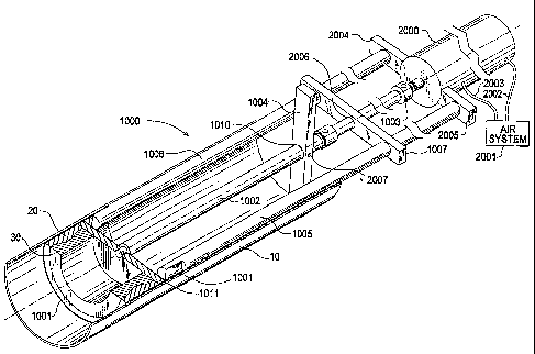
Fig. 4 is a perspective view of the assembly device
for a shaft damper. Assembly device 1000 comprises a
damper holding member 1001 and piston 1002. Elongate
members or rods 1005, 1006 are each attached to base
plate 1007 and members 2005, 2004 respectively. Piston
1002 extends parallel to rods 1005, 1006 through hole
2006 in base plate 1007.
Actuating cylinder 2000 is connected to an end of
piston rod 1003, which is connected to piston 1002.
Actuating cylinder 2000 is a motive member and may
comprise a pressurizable cylinder such as a hydraulic or
pressurized air cylinder, or an electrically actuated
screw or equivalents or combinations thereof. The
instant invention may also be operated by hand by an
operator by pulling on plate 1007 while simultaneously
pushing on piston 1002.
In the preferred embodiment cylinder 2000 comprises
an air cylinder connected by hoses 2002, 2003 to an air
system 2001. Pneumatic air systems are known in the art.
Stop 1004 is attached to a predetermined position on
piston 1002 by a set screw 2007 or other suitable means
of attachment. Stop 1004 extends across a width of shaft
10 in order to limit an insertion length L1, see Fig. 1,
of the piston 1002, and thereby establish a position of
the assembly device, and thereby a position of the shaft
damper, in shaft 10.
5
CA 02494520 2005-01-25
WO 2004/011199 PCT/US2003/019171
Pressing member 1011 is connected to an end of
piston 1002. Pressing member urges the damper
elastomeric member 20 and inertial member 30 out of the
holding member 1001 as the holding member is withdrawn
during installation of the shaft damper into shaft 10.
Pressing member 1011 hasa diameter less than an internal
diameter of holding member 1001.
Fig. 5 is a cross-sectional view of the assembly
device for a shaft damper. An end of rod 1005 comprises
pin 1008 extending radially outward. An end of rod 1006
comprises pin 1009 extending radially outward. Pins 1008,
1009 each engage a slot in damper holding member 1001,
see Fig. 7. Holding member 1001 has a concentric,
sliding fit within shaft bore 40.
Fig. 6 is an end view of the assembly device for a
shaft damper. Rods 1005, 1006 extend parallel to piston
1002. Stop 1004 has a width (A) exceeding a width of
shaft 10.
Fig. 7 is a cross-sectional view of a damper holding
member. Member 1001 is manufactured with an outside
diameter equivalent to the lowest tolerance for an
internal diameter of a shaft 10 in order to allow it to
have a concentric, sliding fit in shaft bore 40. It is
somewhat longer in length than elastomer 20 to
accommodate a connection with rods 1005, 1006.
Connection members 1020, 1021 and 1022 are each
disposed upon an inner surface of holding member 1001.
Each connection member describes an "L" shaped slot or
receiving member, 1020a, 1021a, 1022a, for receiving an
engaging member or pin 1008 or 1009 as described in Fig.
5. Four connecting members disposed about holding member
1001 allows for increased flexibility for releasably
connecting to rods 1005, 1006. One can appreciate that
only two connecting members need be used at any one time.
6
CA 02494520 2005-01-25
WO 2004/011199 PCT/US2003/019171
Any number of connecting members may be used in holding
member 1001, so long as they are present in pairs since
there are two rods 1005, 1006. The holding member 1001 is
releasably connected to rods 1005, 1006 by applying a
partial turn to the holding member to fully engage the
pins 1008, 1009 in each respective connecting member
slot, for example, 1020a and 1022a.
In use, the holding member 1001 is first releasably
connected to rods 1005, 1006 using members 1020, 1021
engaged with pins 1008, 1009. Elastomeric member 20 and
inertial mass 30 are then pressed into the holding member
1001 as shown in Fig. 4. Internal surface 1012 of the
holding member is polished for ease of inserting and
removing elastomeric member 20. A dry lubricant known in
the art, for example graphite but not limited thereto,
may be used to facilitate insertion of the elastomer into
the holding member. Preferably the lubricant is not
reactive with the material comprising the elastomeric
member 20 or shaft 10.
The elastomeric member and inertial member are
inserted into the holding member until they are
substantially flush with a holding member end as shown in
Fig. 7. The compression of the elastomeric member in the
holding member is somewhat greater than the compression
of the elastomer after it is installed in the shaft. For
example, for 25% elastomeric member compression in a
shaft, the elastomeric member compression in the holding
member is approximately 35% to 40%.
As described previously, connecting holding member
1001 to elongate members or rods 1005 and 1006 simply
requires that the holding member connection members 1020,
1021, 1022 be engaged with pins 1008, 1009. Pins 1008,
1009 are inserted respectively into the slots 1020a or
1021a or 1022a as required.
7
CA 02494520 2005-01-25
WO 2004/011199 PCT/US2003/019171
The assembly device with the holding member
connected is then inserted into shaft 10 by insertion of
the rods 1005, 1006 and piston 1002. Insertion of the
holding member 1001, rods and piston proceeds until stop
1004 engages the end of shaft 10. Stop 1004 is
positioned on piston 1002 relative to holding member 1001
in order to result in the holding member and thereby the
damper being placed in the proper installation position
within the shaft 10, for example, at position having a
distance L1 from end 50 as shown in Fig. 1. Set screw
2007 locks stop 1004 in place on piston 1002.
Once the holding member, and thereby the damper, is
properly placed, actuating cylinder 2000 retracts rods
1005,.1006 and thereby retracting holding member 1001.
Holding member 1001 is axially moved to extract it from
bore 40 while pressing member 1011 remains stationary by
operation of cylinder 2000. Therefore, pressing member
1011 holds the damper in place as the holding member 1001
is slidingly disengaged from the damper elastomeric
member 20 and thereby extracted from bore 40. As the
holding member is extracted from shaft 10, elastomeric
member 20 expands against the interior surface of shaft
10 to complete installation of the damper. The assembly
device can then be removed from the shaft and the process
repeated for the next damper installation.
The inventive tool allows the damper to be installed
in a shaft in a precise location without sliding or
rubbing the elastomeric member 20 against the interior
surface of the shaft as it is inserted to the desired
location in the bore. Movement of the elastomeric member
against a rough shaft interior would have a detrimental
effect on the elastomeric member, adversely affecting the
ability of the elastomeric member to engage the shaft, as
well as potentially modifying the damping capability of
8
CA 02494520 2005-01-25
WO 2004/011199 PCT/US2003/019171
the damper. The inventive tool also allows a shaft damper
to be installed without applying a lubricant to the bore
of a shaft.
Fig. 8 is an end view of a damper holding member at
line 8-8 in Fig. 7. Connection members 1020, 1021 and
1022 are shown in holding member 1001. Slots 1020a,
1021a, and 1022a are also shown for receiving pins 1008,
1009.
Although a form of the invention has been described
herein, it will be obvious to those skilled in the art
that variations may be made in the construction and
relation of parts without departing from the spirit and
scope of the invention described herein.
9