Note: Descriptions are shown in the official language in which they were submitted.
CA 02495461 2005-02-15
C GB0303839L
Printeda08-1 '1-2004 DESCPAIVID,
EPa - DG 1
- 1- 0 4.. 11. 2004
A METHOD FOR MAKING A SCREEN ASSEMBLY FOR A VIBRATORY
SEPARATOR
The present invention relates to a method for making
a screen assembly for a vibratory separator.
In the drilling of a borehole in the construction of
an oil or gas well, a drill bit is arranged on the end of
a drill string and is rotated to bore the borehole. A
drilling fluid known as "drilling mud" is pumped through
the drill string to the drill bit to lubricate the drill
bit. The drilling mud is also used to carry the cuttings
produced by the drill bit and other solids to "the surface
through an annulus formed between the drill string and
the borehole. The drilling mud contains expensive
synthetic oil-based lubricants and it is normal therefore
to recover and re-use the used drilling mud, but this
requires the solids to be removed from the drilling mud.
This is achieved by processing the drilling fluid. The
first part of the process is to separate the solids from
the solids laden drilling mud. This is at least partly
achieved with a vibratory separator, such as those shale
shakers disclosed in US 5,265,730, WO 96/33792 and WO
98/16328.
Shale shakers generally comprise an open bottomed
basket having one open discharge end' and a solid walled
feed end. A number of rectangular screens are arranged in
the basket, which are held in C-channel rails located on
the basket walls, such as those disclosed in GB-A-
2,176,424. The basket is arranged on springs above a
receptor for receiving recovered drilling mud. A skip or
ditch is provided beneath the open discharge end of the
basket. A motor is fixed to the basket, which has a drive
1 AMENDED SHEET t~4 11 2004
CA 02495461 2005-02-15
Printeci: 08-11-2004 DESCPAMD C G.B03,0'3$39~
- 2-
rotor provided with an offset clump weight. In use, the
motor rotates the rotor and the offset clump weight,
which causes the basket and the screens fixed thereto to
shake. Solids laden mud is introduced at the feed end of
the basket on to the screens. The shaking motion induces
the solids to move along the screens towards the open
discharge end. Drilling mud passes through the screens.
The recovered drilling mud is received in the receptor
for further processing and the solids pass over the
discharge end of the basket into the ditch or skip.
The screens are generally of one of two types: hook-
strip; and pre-tensiosned.
The hook-strip type of screen comprises several
rectangular layers of mesh in a sandwich, usually
comprising one or two layers of fine grade mesh and a
supporting mesh having larger mesh holes and heavier
gauge wire. The layers of mesh are joined at each side
edge by a strip which is in the form of an elongate hook.
In use, the elongate hook is 'hooked on to a. tensioning
device arranged along each side of a shale shaker. The:
shale shaker further- comprises a crowned- set of
supporting members, which run along the length of -the
basket of the shaker, over which the layers of mesh are
tensioned. An example of this type of screen is disclosed
in GB-A-1,526,663. The supporting mesh may be provided
with or replaced by a panel having apertures therein.
The pre-tensioned type of screen comprises several
rectangular layers of mesh, usually comprising one or two
layers of fine grade mesh and a supporting mesh having
30. larger mesh holes and heavier gauge wire. The layers of
mesh are pre-tensioned on a=rigid support comprising a
rectangular angle iron frame and adhered thereto. The
2 AMENDED SHEET 04-11-2004;
CA 02495461 2005-02-15
Printed: 08-11-2004 DESCP,4M D' c GB~3U3s3J
v. . .. . . ~7 ;.~iit:. .. , .,.
- 3-
screen is then inserted into C-channel rails arranged in
a basket of a shale shaker. An example of this type of
screen is disclosed in GB-A-1,578,948.
A further example of a known rigid support is
disclosed in PCT Publication No. WO 01/76719, which
discloses, amongst other things, a flat panel like
portion having apertures therein and wing portions. which
are folded to form a support structure, which may be made
from a single sheet of material. This rigid support has
been assigned the Trade Mark "UNIBODY" by the applicants.
The layers of mesh in the screens wears out
frequently and therefore needs to be easily replaceable.
Shale shakers are generally in the order of 5ft wide and
lOft long. A screen of dimensions 4ft wide by lOft long
is difficult to handle, replace and transport. It is
known to use two, three, four or more screens in a single
shale shaker. A standard size of screen currently used is
of the order of 4ft by 3ft.
It is important to achieve maximum screening area in
a gi.ven space and to obviate the need for mechanisms for
fixing screen assemblies to shakers which blind areas of
the screening material and which will decrease the screen
assembly's screen3.ng capacity.
The present invention attempts to provide a method
for tightening non-flat screening material on a screen
assembly; screens with such tightened screening material;
and methods for using such screens.
US 2002/0000399 co-owned by the applicant for the
present case, discloses inter alia a method of making a
screen comprising the steps of heating a perforate plate
in a heat press, dipping the perforate plate in a
fluidized bed of epoxy. The layers of screening material
3;, AMENDED SHEET 04-11-2004;
CA 02495461 2005-02-15
Printed: 03-1 1-2004 DESG,PAMD; C GB030A
4-
and the perforate plate are then placed on a TeflonPI
coated steel panel and a further Teflorn'K coated panel is
placed on top of the screening material and perforate
panel to form a sandwich which is then placed in an oven.
The present invention also attempts to provide a
screen assembly, which will increase the life of layers
of screening material arranged thereon.
WO 02/36237 co-owned by the applicant for the
present case, discloses inter alia a screen assembly
having layers of screening material sewn together with
sewing material.
The prior art discloses a wide variety of vibrating
screens, devices which use the, shale shakers, and
screens for shale shakers. The screens catch, filter, or
remove solids from fluid to be treated by a vibratory
separator or shale shaker.
Certain prior art screens and screen assemblies for
vibratory separators and shale shakers have areas of
screening material which are improperly tensioned,
including but not limited to, screen assemblies with
areas of screen material surrounded by epoxy_ With
certain such screens, these areas of screening material
are often rippled, or wavy, i.e., it is not flat and not,
therefore, properly tensioned or not optimally tensioned.
A variety of problems and disadvantages are associated
with such screens that have areas of rippled screening
material: poor conveyance of solids across a screen;
reduced screen life; and increased screen cost.
The present invention discloses, a method for makixlg
a screen assembly for a vibratory separator, the method
comprising the steps of sewing together with sewing
material at least two layers of fine screening material,
4 AMENDED SHEET 04-11-2004'
CA 02495461 2005-02-15
.u õ# _ ...
Printecl: 08-11-2004 DESCPAMD: C CB0303S39R
- 5-
characterised in that the sewn-together at least two
layers of fine screening material is placed in a heated
platen apparatus, placing a coarse mesh layer adjacent
the at least two layers of screening material on the
heated platen, placing adjacent the coarse mesh layer a
support with heat activated material thereon for adhering
the support to the coarse mesh layer, and heating the
coarse mesh layer, the sewn together at least two layers
of fine screening material, and the support to adhere the
support to the coarse mesh layer and the at least two
layers of fine screening material to the coarse mesh
layer.
The number of layers of fine screening material may
be two, three, four or more layers.
Preferably, the method further comprises the step of
preheating the sewn-together at least two layers of fine
screening material prior to placing them on the heating
apparatus. Advantageously, the sewn-together at least two
layers of fine screening material are preheated for
between thirty and sixty seconds. Preferably, the at
least two-layers of fine screening material are comprised
o a plurality of interwoven wires and wherein the
preheating is sufficient to effect elongation of the
wires of the at least two layers of fine screening
material.
Preferably, the method further comprises the step of
applying glue to the coarse mesh layer. Advantageously,
the glue is applied.in at least one line on the coarse
mesh layer. At least one line on the coarse mesh layer or
in a plurality of spaced-apart lines. The line(s) may be
straight, curved, zig-zag, patterned, wavy, etc.
Preferably, the at least one line is at least two spaced-
5': AMENDED SHEET 04,11-2004
CA 02495461 2005-02-15
C:GBt~3Q~3391x
Printecl: 08-11-2DO4 DESCPANID~~
- 6-
apart lines. Advantageously, the at least one line is
applied lengthwise on the coarse mesh layer. Preferably,
the at least one line is applied in an amount sufficient
to effect.a barrier to solids migration between the
coarse mesh layer and a lowermost layer of the at least
two layers of fine screening material, the lowermost
layer adjacent the coarse mesh layer.
Preferably, the coarse mesh layer ranges between 15
mesh and 25 mesh. Advantageously, the at least two layers
of fine screening material comprises a first layer and a
second layer of fine mesh.Advantageously, -one of the two
layers of fine mesh ranges between 30 mesh and 200 mesh
and the other layer ranges between 50 mesh and 300 mesh.
Preferably, the support is a frame. Advantageously,
the support is a perforate plate.
Advantageously, the heat activated material is epoxy
adhesive. Preferably, following adhering of the coarse
mesh layer to the support, cure of the epoxy adhesive is
accelerated. Advantageously, the heat activated material
is hot melt glue. Preferably, the curing of the hot melt
-glue is facilitated by moisture.
Preferably, each of the at least two layers of fine
screening material are comprised of interwoven wires, the
coarse mesh layer is comprised of interwoven wires, and
wires of the coarse mesh layer have a diameter at least
three times a diameter of wires of the at least two
layers of fine screening material. Preferably, the
heating coarse mesh layer, the sewn-together at least two
layers of fine screening material, and the support is
heated in the heatecl platen apparatus for between 10
minutes and 18 minutes. Advantageously, the heating
coarse mesh layer, the sewn-together at least two layers
6 AMENDED SHEET p4-11-2004
CA 02495461 2005-02-15
Printed: 03 11 2004; DESCPAMDI C CB0'~C~3.d39 7-
of fine screening material, and the support is heated in
the heated platen apparatus at 232 Celsius (450 F).
Preferably, the heat activated material is curable and
wherein the coarse mesh layer, sewn-together at least two
layers of fine screening material, and the support is
heated in the heated platen apparatus until the heat
activated material is cured. Advantageously, the heated
platen apparatus comprises a bed and an upper heated
member.
7 AMENDED SHEET 04-11-2004
CA 02495461 2005-02-15
Printp-ci: 08-11-2004 DESCPAMD cGB03C~3839
.. ~ ,.
_ 8_
For a better understanding of the present invention,
reference will now be made, by way of example, to the
accompanying drawings, in which:
Figures 1A and 1B are cross-section views of a
screen assembly in accordance with the present invention;
Figures 2A is a top view of a frame for a screening
assembly in accordance with the present invention;
Figure 2B is a top view of screening material for a
screen in accordance with the present invention; Figure
2C is a top view of a screen assembly in accordance with
the present invention with a frame as in Figure 2A and
screening material as in Figure 2B;
Figure 3 is=a cross-section view of a glue bead for
screening material combinations in accordance with the
present invention;
Figure 4A is a top view of a screen assembly in
accordance with the present invention; Figure 4B is a
bottom view of the screen assembly of Figure 4A; Figure
4C is an end view of one end of the screen assembly of
Figure 4A -(and the opposing end is identical to that of
Figure 4C) ; Figure 4D is a side view of one side of the
screeri assembly of Figure 4A (and the opposing side is
identical to that of Figure 4C); Figure 4E is a partial
bottom perspective view of the screen assembly of 4A;
_Figure 4F is a partial bottom view of the screen assembly
of Figure 4A;
Figure 5 is a perspective view of a shale shaker in
accordance with the present invention;
Figure 6 is a perspective view of a screen assembly
in accordance with the present invention;
Figure 7A is a side view and Figure 7B is a front
view of a heating apparatus;
8 AMENDED SHEET t~~-11;2004
CA 02495461 2005-02-15
P-rinted: 08-11-2004; UESGPf/~N1D; C C~BO3 C~~8'~9
.__..... ..._.... : :;.
- 9-
Figure 8A is an end exploded view of a screen
assembly in accordance with the present invention;
Figure 8B is a top view of a coarse mesh layer of the
screen assembly of Figure 8A; Figure 8C is a top view of
the screen assembly of Figure 8A;
Figure 9 is a top view of a screen assembly in
accordance with the present invention;
Figures 10 and 11 are cross-section views of parts
of the screen of Figure 56;
Figure 12 is a top view of a screen assembly in J
accordance with the present invention;
Figures 13, 14, 15, 18 and 19 are cross-section
views of screen assemblies in accordance with the present
invention;
Figure 16 is a top view of a screen assembly in
accordance with the present invention;
Figure 17 i.s a top view of a screen assembly in
accordance with the present invention;
Figures 20A and B are schematic views showing steps
in a method in accordance with the present invention for
making screen assemblies in accordance with the present
invention;
Figure 21 is a schematic view showing steps in a
method in accordance with the present invention for
making screen assemblies in accordance with the present
invention;
Figure 22 is a perspective view of a screen assembly
in accordance with the present invention.
Figure 23A is a top schematic view of part of a
screen assembly in accordance with the present invention;
Figure 23B is a side view of the screen assembly of
Figure 23A;
g! AMENDED SHEET 04-11-.2004;
CA 02495461 2005-02-15
Pr-inteci` 08-11,2004 [:)ESCPAMD i C GB03C~ 36~B9"
- 10-
Figure 24A is a top schematic view of part of a
screen assembly in accordance with the present invention;
Figure 24B is a side view of the screen assembly of
Figure 24A;
Figure 25 is a top view of a screen assembly in
accordance with the present invention;
Figure 26 is a top view of a screen assembly in
accordance with the present invention;
Figure 27 is a side view of a ridge of three-
dimensional screen assembly in accordance with the
present invention;
Figure 28A 3.s a top view of screen assembly in
accordance with the present invention; Figure 28B is an
end view of the screen assembly of Figure 28A;
Figure 1A shows a glued-together screen combination
10 with lower coarse mesh 11 and upper fine mesh or
meshes 12. Following the gluing operation and curing of
the glue 131, portions of the upper mesh or meshes are
rippled, wavy, or non-flat (as shown). Following
mounting (by epoxy powder or by hot melt glue) of such a
screen combination 10 to a tubular frame and then
subjecting the resulting screen assembly to vibration on
a vibratory shaker while fluid at a temperature above
ambient temperature (e.g. at least five to twenty degrees
hotter than ambient and including, but not limited to
drilling fluids from a weil]aore up to 71 Celsi.us (160 F)
or higher) is fed to the screen assembly, the non-flat
portions of the screening material tighten and flatten,
as shown in Figure 1B.
Figure 3 shows a cross-section or one glue bead's B
profile applied to a screen S. The distance "a" is, in
this embodiment, about one-sixteenth of an inch but may
10 AMENDED SHEET 04-11-2004
CA 02495461 2005-02-15
Printed: 03-11-2004 DESGPAMD C GB0303839~;
- 11-
be any desired height as applied. Preferably the
distance "b" is as thin as possible. Alternatively, the
raised portion (all above the level "b") is,deleted.
Figure 2C shows a screen assembly 100 in accordance
with the present invention which has screening material
102 (Figure 2B) secured onto a tubular frame 104 (Figure
2A). in other aspects the frame 104 is deleted and a
hookstrip (of any known shape and/or configuration) is
connected to each of two spaced-apart sides of the
screening material 102. The screening material is any
multi-layer screen in accordance with the present
invention with two, three or more layers glued together
as described herein with moisture curing hot melt glue in
accordance with the present invention. The multiple
layers of glued together screening material 102 and the
tubular frame 104 are encapsulated with a powdered epoxy
in a semi-cured state and then the semi-cured powdered
epoxy is heated, bonding the screening material to the
frame 104. Following cooling, the cured powdered epoxy
encapsulates the screen material, adjacent to the frame
and the frame forming a unitary structure.
The tubular frame 104 has a plurality of
crossmembers 106 that extend between and whose ends are
connected to sides 107, 108 of the frame 104. End
members 103, 105 are at the ends of the frame 104. In
certain aspects there are nine crossmembers 106. The
tubular frame 104 and its parts may be made of hollow or
solids beams, tubes, bars, or rods of metal (e.g. steel,
aluminum, zinc, stainless steel and/or alloys of any of
these), plastic, or fiberglass. Metal and/or plastic
parts may be welded together.
In one particular aspect the frame 104 is made of
11; AMENDED SHEET 04-11=2004'
~ , .,... , .
B 303639,~
Pi-inted: 03-11-2004 DES!CPAMD C G
qp,
- 12-
hollow square cross-section tubes 103, 104, 107, 108 with
a 0.766 inch square cross-section and round cross-section
tubes 106 with a 0.601 square inch cross-section. The
screen assembly 100 (and the frame 104) may have any
.5 suitable desired length and width. In one aspect the
screening material is made 'of strands of 304, or 316
stainless steel and the frame is made of carbon steel.
In another aspect the crossmembers 106 and/or end members
103, 105 are made of 'tubular members with a circular,
oval, or elliptical cross-section.
In one aspect the screening material is bonded to
the frame with a powdered epoxy material. The frame is
heated then dipped into a fluidized bed of the powder
which completely encapsulates the frame in a semi-cured
state and, in one particular aspect, with a thickness of
about 35 mils. The frame and screening material are put
on a heated platen with the screening material (in one
case three layers 170 x 105 mesh, 105 x 64 mesh and 19
mesh glued together with a method in accordance with the
present invention) below the frame. Upon heating to
about 232 Celsius (450 degrees F), the powdered adhesive
is heated and flows down over the wires of the screening
material. In one aspect the wires are partially coated
and in another they are, preferably, completely
encapsulated with the adhesive. The frame with the
screening material on it is left on the heated platen
until the coating is cured, being heated when it is
curing. In one aspect the coating encapsulates the
frame. Any glue bead pattern and application method
described in the parent patent applications of this
invention may be used in accordance with the present
invention.
CA 02495461 2005-02-15
12; AMENDED SHEET 04-11-2004
CA 02495461 2005-02-15
,.....
Printed: 00-11-20042 DESCPAMD C_G3,O303839-
- 13-
Figures 4A - 4F show a screen -assembly 40 in
accordance with the present invention which has a tubular
frame 42 with ends 44 and interconnected sides 45. A
screening material combination 50 is bonded with epoxy
powder to the tubular frame 42. A crossmember 41 (of a
plurality of spaced-apart crossmembers 43 that extend
between and have ends connected to the sides 45) has two
notches 46 for receiving an upstanding member of a shale
shaker deck.
In certain shale shakers in which screen assemblies
without crossmembers such as the crossmember 41 are used,
one or more upstanding members are used for proper screen
assembly positioning or for stabilizing screen assemblies
in position. Rather than removing such upstanding
member(s), a screen assembly in accordance with the
present invention may be installed on such a shaker deck
so that the upstanding member (which is perpendicular to
the crossmember 41 as viewed from above or below) is
received in and projects into one (or more) of the
notches 46. With a screen assembly 40 as shown, the
cros-smembers 43 on either side of the crossmember 41 are
suffici.ently spaced-apart from the crossmember 41 that
the upstanding member does not contact the adjacent
crossmembers 43. Although only one notch 46 can
accommodate an upstanding member, by using two notches
46, proper emplacement of the screen assembly 40 over the
upstanding member is made "fool proof" - i.e. whichever
side of the screen assembly is placed nearest the
shaker's exit end (or fluid introduction end) one of the
notches will be above the upstanding member. Of course
it is within the scope of the present invention to place
aligned notches on adjacent crossmembers to accommodate
13 4 AMENDED SHEET 04 11 2004
CA 02495461 2005-02-15
~
Printed: 03-11-2004 DESCPAMD C CSta 303b39i
- 14-
an upstanding member of length sufficient to extend
beyond the distance separating two, three, four or more.
The screen assembly 40 as shown has a multi-layer
combination 50 of layers of screening material glued
together with moisture curing hot melt glue in a glue
pattern 62. The multi-layer glued-together combination
60 is bonded to the tubular frame 42 with cured epoxy
powder. As shown the screen assembly 40 has not yet been
vibrated with fluid flowing onto it and areas 64 of
screening material between glue lines is non-flat or
rippled (as shown). Subjecting the screen assembly 40 to
vibration and fluid flow in accordance with the present
invention will result, in accordance with the present
invention, in the tightening of the non-flat screening
material in the areas 64.
It is within the scope of the present invention to
provide a screen assembly with a support for glued-
together combination of multiple layers of screening
material (e.g. any glued-together multi-layer combination
disclosed herein or in parent patent applications of this
invention) that is a perforated plate (instead of the
tubular frame, e.g. -3:rnstead of the tubular frame 14,
-E'igure 1B; the tubular frame 42, Figure 4A; or the
tubular frame 104, Figure 2A). Any known perforated
plate may be used. Such a screen assembly with a
perforated plate is within the scope of the present
invention with or without non-flat screening areas; and
such a screen assembly may have spaced-apart side
hookstrips for mounting in a shale shaker.
30, Tightening of non-flat screening areas (e.g. as in
the screen assemblies.of Figures 1A, 2A and 4A) may, in
accordance with the present invention, be facilitated by
14'; AMENDED SHEET 04-11-2004
CA 02495461 2005-02-15
L004il D FSC,'PANI D' C u
Pririfeci: 08 1 1-... ~B 03.t~3~S39~
- 15-
flowing fluid onto the screen assemblies that is above
ambient temperature. In certain aspects the fluid
temperature is between five degrees to twenty degrees
above ambient temperature. Such a temperature may be
achieved using any known heater apparatus and/or by
pumping fluid, e.g., but not limited to, pumping fluid
with the typical known fluid pumping apparatus associated
with known shale shakers. In other aspects, when the
fluid pumped onto the screen assemblies is drilling fluid
from a welibore being drilled, the drilling fluid having
drilled cuttings, etc. therein, the fluid temperature may
be between 49 Celsa.us (120 F) and 71 Celsius (160 F) or
higher.
In one particular embodiment a screen assembly as in
Figure 4A was run on two commercially available King
Cobra shale shakers for a total of about 96 hours with 16
pound oil-based drilling fluid with drilled cuttings and
shale solids therein being treated by the screen
assembly. Following this use the screening material
areas which were non-flat were tightened. in another
embodiment, a screen assembly as in Figure -4A was run on
a Kirig Cabra_ shaker for 120 hours and fluid slightly
above ambient temperature (e.g. four to twelve degrees F
above ambient) was fed to the screen assembly, the fluid
weighing about` nine pounds per gallon and containing
sand, water, and bentonite (by weight, about 92% water,
4% sand and 4% bentonite). Following this use screening
material areas that were non-flat were tightened.
It is within the scope of this invention to tighten
non-flat screening material areas between glue lines of a
multi-layer screening material combination of a screen'
assembly by vibrating the screen assembly for a
15 . AMENDED SHEET 04-11-2004
CA 02495461 2005-02-15
._..e ........ ...... . 1
Print,eci: 018-1 1-2004 DESCPAMD C GB0303839,1
__,..
- 16-
sufficient time period on a shale shaker while feeding
fluid thereto at a sufficiently high temperature to
effect tightening of the non-flat areas. Such fluid may
or may not contain drilled cuttings, sand, and/or other
solids.
In one method in accordance with the present
invention a combination of two layers of screening
material is sewn together by any sewing method or
technique described herein with any stitch or stitch
pattern described herein. In one aspect, the two layers
range between 30 and 250 mesh; in one aspect one layer is
between 30 and 200 mesh and the other layer is between 50
and 300 mesh; and in one particular aspect one layer is
160 mesh and the other is 180 mesh - both mesh layers of
stainless steel wire. The two-layered combination is
placed on the bottom base of a heated platen and a layer
of coarse mesh (e.g. between 18 to 30 mesh and i.n one
aspect 20 mesh) is placed on top of them. A frame (or
plate) previously coated with adhesive material, e.g. but
not limited to, powdered epoxy material, is then placed
on top of the coarse mesh. One or more lines of glue are
on the- coarse mesh layer (lengthwise, widthwise, curved
and/or in any known pattern or spacing). The heated
platen' s top member is then lowered down onto the frame.
8y heating these components in this manner, the two fine
screening mesh layers are glued together and the frame
(or support) is adhered to the mesh layers. All three
mesh layers are bonded together at points where they are
contacted by the epoxy material. Preferably, at least
some of the wires of the coarse mesh layer and/or of the
two screening materi.al layers are encapsulated in the
adhesive. Optionally, the two layers of screening
16 AMENDED SHEET 04 1.1 200~
CA 02495461 2005-02-15
Printed: 05-11-2004;, DESCFAMD' c GB03C) 3=81 39:=
- 17-
material and the coarse mesh layer with one or more glue
lines are all three preheated together and joined
together and then the fraame is joined to the three
layers.
Any suitable glue (in one aspect, a heat activated
glue that is quick curing), epoxy, or adhesive (although
these are not equivalents of each other) may be used to
adhere the frame to the mesh layers. The frame (or
support) may be adhered over substantially all its area
to the coarse mesh layer and there may also be adherence
to one or both of the other screening material layers
depending on the epoxy, glue or adhesive used and on its
amount. In one particular aspect the frame (or support)
is heated and then coated (e.g. in a fluidized bed or
with a spray system) with epoxy powder as described
herein (or according to any method for such coating as is
well known in the prior art) and the epoxy powder is only
partially or semi-cured. Any suitable epoxy material
known in the prior art may be used. In one particular
aspect one, two, three, four or more glue beads (any
dis_c-losed herein) are applied lengthWise and/or across
-the width of the coarse mesh layer (e.g. in any pattern.
and -by any glue machine or glue apparatus in accordance
with the present invention, disclosed herein, or referred
to herein) prior to its imposition on top of the two
sewn-together mesh layers.
In those embodiments in which a three layered screen
panel - lowermost coarse mesh beneath two fine mesh
layers - is preheated prior to its connection to a frame,
plate, or support, wires of the two fine meshes expand
and elongate more than the wires of the coarse mesh
layer. For example, with a top mesh layer of 180 mesh
17 AMENDED SHEET 04-11 .22004
CA 02495461 2005-02-15
Printed: Qc 11 2004 DESGRA`MD C GB0303839:
- 1$-
made of wire .0012" in diameter; a middle mesh layer of
160 mesh with wire of .00141' diameter; and a coarse mesh
layer of 20 mesh with wires of .0065" diameter, the finer
mesh wires elongate more and more quickly than do the
wires of the coarse mesh layer. Thus it is preferred for
such an embodiment that the pre-heat time (prior to
imposition of a frame, etc.) be sufficient to allow the
wires of the coarse mesh to elongate to the same extent
as the wires of the fine meshes. Optionally, following
imposition of the epoxy-coated frame on the coarse mesh
layer, the cure of the epoxy can be accelerated (e.g.
with cure accelerator materials and/or by mechanical
cooling apparatus) to prevent 'the coarse mesh wires from
returning to their original size. If the cure is not
rapid enough, quick contraction of the coarse mesh wires
can crack the epoxy and result in a loss of desired
tension in the fi.ner meshes. in one aspect the wire
diameter of the coarse mesh wires is at least three times
that of the wire diameter of the fine mesh wires and in
one particular aspect at least four times.
Also, the present inventors have found that the
addi=tion of adhesive promoter materials and/or particles
of color pigment (e.g. red pigmentation material) to
epoxy material to produce a hardened epoxy bond on a
frame, support, or screen assembly, can result in
undesirable cracking and non-uniform curing of the epoxy
,material. Preheating a combination of screen layers and
a support together can also result in undesirable
cracking. Such cracking and non-uniformity is reduced by
using a method as described above in which a frame with
epoxy material in a semi-cured state is placed with
layers of screening material and then these components
18+ AMENDED SHEET 0~ ~ 1-2004
CA 02495461 2005-02-15
_. _ ......... .,
Pr-inted: 08-11-^iJ04~1 DESCPAMD C CCBU3C-;;839,k
- 19-
are heated as described, e.g. in a heated platen
apparatus. In one particular aspect of such a method to
produce such a screen assembly, a two layer screen
combination with a layer of 160 mesh and a layer of 180
mesh, both stainless steel wire meshes, is produced by
sewing the two layers together in accordance with the
present invention with a stitch pattern in accordance
with the present invention, including, but not limited
to, with a lock stitch. A layer of coarse mesh (20 mesh,
stainless steel) with one, two or more lengthwise glue
beads (in one aspect, four equally spaced-apart glue
beads from one side to the other, straight or in a curved
shape as viewed from above; and in one aspect a plurality
of glue beads about 78mm (3 1/16") apart or about 33mm (1
11/32") apart) (produced by a glue machine in accordance
with the present invention) is placed on top of the two
finer mesh layers in a heated platen and a tubular frame
made of carbon s-teel with four sides and a plurality of
crossbars (e.g., but not limited to, nine spaced-apart)
is placed on top of the coarse mesh, the tubular frame
coated with -semi-cured epoxy material, e.g., but not
limited to as- descxibed in U.S. Patents 6,267_,247;
6,290,0-68e and 5,876,552, all incorporated fully herein
for all purposes. The platen is closed and the
components are heated at about 232 Celsius (450 F) for
about 10 to 18 minutes. The resulting screen assembly is
removed from the platen and allowed to cool. Optionally,
only one fine mesh layer is used. Optionally, preheating
for any step of any method her,ei.n can be accomplished in
an oven. Optionally, the coarse mesh layer is first
joined to the two layers of screening material and then
the resulting three layer combination is joined to a
10 ` AMENDED SHEET 04-11-2004
CA 02495461 2005-02-15
Printed: 05-11'-2004 DESGPAMc- GB0303839
- 20-
frame or support.
Figures 7A and 7B show a heated platen apparatus for
use in methods described above with an upper movable
heatable member 91 and a tray, bed or support 92 on which
screen assembly layers and frame (or plate) are
positioned. The member 92 is movable by a moving
apparatus 93 shown schematically in Figures 7A and 7B.
Alternatively, the tray 92 can be heated with or without
heating the member 91.
The glue of the glue lines or beads placed on a
lower coarse mesh provides a barrier that prevents the
migration of solids across the screen assembly between
the coarse mesh layer and the fine mesh layer above the
coarse mesh layer. For example, if a hole is made in the
upper fine mesh layers permitting solids to flow through
them, such solids can move across the screen assembly on
top of the coarse mesh layer (beneath the fine mesh
layers) causing additional damage. A glue line or bead
on the coarse mesh layer acts as a barrier to the
movement -of such solids. I-n certain aspects these glue
-beads are generally oval, circular, or generally semi-
oval or semi circula.r in cross-section with a diameter or
height between 3mm (1/8") and 4.7mm (3/16") . In certain
aspects glue in a pattern or series of beads on the two
fine mesh layers is between 1.6mm (1/16") to 3mm (1/8")
in height or diameter. In certain aspects after being
heated by the platen, the glue beads are flat.
Referring now to Figure 5, a shale shaker 210 in
accordance with the present invention has a screen
assembly 220 (with screen or screening cloth or mesh as
desired) in accordance with the present invention mounted
on vibratable screen mounting apparatus or "basket" 212.
2Q AMENDED SHEET 04-11-2004
CA 02495461 2005-02-15
Pr-inted: 0~ 11 `00 ~ DESGP,4MD" C GBG3~33;3
....._... , u
- 21-
The screen assembly 220 may be any screen assembly
disclosed herein or have any combination of any feature
or features of any screen, screen assemblies or screen
part disclosed herein in accordance with the present
invention; and any such screen may be used with any
appropriate known shaker or screening apparatus
including, but not limited to, a vibratory separator like
the shale shaker 210. The basket 212 is mounted on
springs 214 (only two shown; two as shown are on the
opposite side) which are supported from a frame 216. The
basket 212 is vibrated by a motor 202 and interconnected
vibrating apparatus 218 which is mounted on the basket
212 for vibrating the basket and the screens. Elevator
apparatus 208 provides for raising and lowering of the
basket end. The screen assembly 220 may be any screen
assembly disclosed herein in accordance with the present
invention.
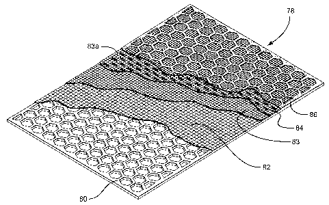
Figure 6 shows a screen assembly 78 in accordance
with the present invention (shown with various layers
partially cut away but which extend across the surface of
the screen assembly). made by a method in accordance with
the pres-ent invention as described above wherein the two
upper fine mesh layers are sewn-together screening
material layers 83 and 84 sewn together with stitching
83a (which extends over substantially all the surface of
the two layers but is only shown partially for purposes
of illustration); the coarse mesh layer is layer 82; the
support is a perforated plate 80 which is initially
coated with epoxy 86 which upon curing, assumes a pattern
like that of the openings of the perforated plate 80.
Optionally either layer 83 or 84 may be deleted (thereby
eliminating the step of sewing two fine mesh layers
21 AMENDED SHEET 04-11-2004
CA 02495461 2005-02-15
. ..... . u~:
P `~ L~ESCP~,NiD C ra BC~3 A) 3839t
rin~~eci: 0~ 11-2Q0 ~ = F,
- 22-
together).
Figures 8A - 8C show a screen assembly 110 in
accordance with the present invention which has two sewn-
together upper screening layers 111, 112 made of fine
screening material [sewn by any method described herein,
e.g. with thread 111a shown for the purposes of
illustration loose and not in a tightened sewn stitch]; a
coarse mesh layer of screening material 113; and a
perforated plate support 114. Hookstrips 115 extend
along opposed sides of the screen assembly 110. The
hookstrips 115 are shown as "C" shaped, but it is within
the scope of this invention to use any known hookstrip
shape or configuration. Any known fine screening mesh
and coarse mesh may be used for the layers 111, 112 and
113, respectively, including, but not limited to, those
described or referred to above. Any suitable known plate
may be used for the plate 114.
Figure 8B shows a plurality of glue beads 116
extending across the coarse mesh layer 113 (the actual
mesh and weave of the coarse mesh layer is not shown in
Figure 8B)_ . Any desired number of beads 116 may be used
from one-to seven or more_. Optionally, the beads extend
lengthwise (from top to bottom in Figure 8B) rather than
across the coarse mesh layer. Optionally a pattern of
beads that intersect is used on the coarse mesh layer,
including, but not limited to, in any pattern disclosed
or referred to herein. Optionally, the plate 114 is
deleted. Optionally, the plate 114 and hookstrips 115
are deleted and a frame or strip support is used.
Optionally the plate 114 is deleted and a strip support
is used.
Figure 9 shows a screen assembly 3000 with some
22': AMENDED SHEET 04-11-2004
CA 02495461 2005-02-15
Priaated: 0 11 200~ DESCPAMD`( C'GBQ303~39=
- 23-
parts like those of prior art U.S. Patent 4,575,421;
however as described below, various parts of the screen
assembly 3000 are held together by sewing material (e.g.
thread, wire, string, filaments, cord, twine, yard or
fiber). U.S. Patent 4,575,421 is incorporated here fully
for all purposes, including; but not limited to the parts
of the screen assembly 3000 which are like the parts of
the screen assemblies in the patent. Sides 3008 may be
any known channel-shaped member, hookstrip, or frame
sides. Alternatively a rigid frame with four sides may
be used.
A plurality of layers of screening material 3002,
3003, and 3004 are positioned above a plate 3001 (like
the plates, including but not limited to the plate 11, in
U.S. 4,575,421). The layers 3002, 3003 and 3004 are like
the layers, respectively, 24, 25, 26 as described in U.S.
4,575,421. It is, however, within the scope of this
invention to delete any one or two of the layers and for
any of the layers 3002, 3003, 3004 to be any screening
material or mesh disclos_ed herein or combination thereof;
anc3. rt is within -the scope of this invention for the
plate 30-01 to be any support plate structure screen,
frame, or series of strips (although these things are not
legal equivalents) known in the art.
The layers 3002, 3003, 3004 are sewn together by
sewing material. Exemplary'lines of sewing material 3014
and 3016 are shown in Figures 9, 10,'and 11. It is to
be understood that such lines of sewing material sewing
_ the layers together may extend in spaced-apart fashion
over substantially all of the surface of the layers with
any desired spacing between lines of sewing material. it
is also within the scope of this invention for the sewing
23, AMENDED SHEET 04-11=2004:
CA 02495461 2005-02-15
,
Printed Q8-11-20F04,, DESCPA'MD CGB-03018u0
- 24 -
material to be in lines that are generally parallel to
the sides of the screening layers, as shown; for the
sewing material lines to extend diagonally across the
screening material; for the sewing material lines to be
at an angle other than diagonal across the screening
material; and/or for lines of sewing material to
intersect, forming any desired pattern including, but not
limited to, a pattern corresponding to shapes formed by
members of a lower supporting mesh, structure or plate.
Such lines of sewing material may also be used to join
together either layers 3002 and 3003, 3002 and 3004,
and/or layers 3003 and 3004.
Lines of sewing material 3010 and 3012 sew together
the plate 3001 and the layers 3002, 3003 and 3004. The
lines 3010 and 3012 may take any of the forms and
positions described above for the lines 3014, 3016. In
one aspect "edge stitching" may be used to sew screening
material to the plate. It is also within the scope of
this invention to sew one, two., three or more layers of
screening material to a frame that supports the screening
material.
The sew3.-ng material used to sew together any two or
more layers -of screening material and/or mesh, or any
support structure or plate and one or more layers of
screening material may be any suitable known sewing
material, including, but not limited to, thread, wire,
yarn, string, twine, cord, and filament line (any of
which may be mono- or multi- strand or filament -with
different or similar strands or filaments in multi-
component sewing material). Such sewing material may be
made, e.g., of natural, plastic, or synthetic thread,
yarn, cord or wire materials; composite materials;
24 AMENDED SHEET 04-11-2004
CA 02495461 2005-02-15
_ ._.
õPrinteci: 08 11'-20041 DESGPAN1D` C,GBO303839
- 25 -
polymer(s); elastomer(s); rubber; phenolic resin(s);
metal (including but not limited to steel, stainless
steel, bronze, brass, copper, zinc, aluminum and any
combination or alloys of theya) ; KEVLAR material; and
polytetrafluoroethylene or Teflon material - any of
which may be coated with plastic, metal, polymer,
elastomer, or resin. Sewing material of any cross-
sectional surface area and/or cross-sectional shape (or
of any suitable diameter) may be used. Different sewing
materials may be used for different stitches and/or lines
of stitches on a single screen or screen assembly. The
needle(s) used may be any suitable known needle and may
be made of any suitable metal, plastic, composite, and/or
fiberglass material. In one particular aspect KEVLAR
thread with a diameter of .009 inches is used. In one
particular screen using such REVLAR thread there are
three layers of screening material sewn together.
The sewing together of any two or more items may be
done in accordance with the present invention by hand,
with a manually operated sewing device or machine, or
with an.y automatic -sewing' machine. Any known sewing
stitch or pattern may be used. In certain aspects a
sewing needle is used which is sized so that damage to
the layers and/or support is minimized or eliminated. In
one such aspect, a needle is selected of such size that
it penetrates between and moves between adjacent wires or
screen components rather than making a dent, gouge, gash,
tear or recess in a wire (or screen component) of a
screen and rather than breaking or weakening a wire of a
screen.
Any stitch or line of sewing material may,
optionally, be deleted from the screen assembly 3000 (or
' 25. AMENDED SHEET 2004
CA 02495461 2005-02-15
' . ' _ ~p = ~
~ Printed: õOS 11 20~%t~ DESCPAIVID C GB03t~383~ 1
~,, . . .~
- 26 -
from any sewn screen assembly disclosed herein). It i,s
within 'the scope of this invention to delete all lines
3012, 3014 and all lines sewing together the layers of
screening material 3002, 3003, 3004 and to rely on the
lines 3010, 3012 and others spaced-apart from them that
sew together all of the layers of screening material and
the plate 3001. Alternatively between lines like the
line 3010, lines like the line 3014 may be used to hold
the layers 3002 - 3004 together (and likewise for lines
like 3012 and 3016).
U.S. Patent 4,575,421 refers to an adhesive or
bonding that secures parts together. The screen 3000 may
be made with no such adhesive or bonding. Alternatively,
such adhesive (e.g., but not limited to, glue or epoxy)
or bonding may be used in addition to any sewing material
described above; or a combination of one or more spaced-
apart lines of sewing material and adhesive between
and/or on or beneath such lines may be used. In one
aspect the layers 3002 - 3004 may be adhesively secured
together and lines like the lines 3010 and/or 3012 used
to sew the layer-s to the plate 3001, or the layers 3002 -
3004 are sewn together and then adhesively secured to the
plate 3001. Any- two or more metal layers and/or plate
may be sintered together over a portion or over
substantially all of this area. One or more separate,
individual stitches or knots of sewing material may be
used instead of a line of a continuous thread, etc. for
any line of sewing material described herein.
Figures 23A and 23B show screen assembly 3108 in
accordance with the present invention with a perforated
plate 3110 (which may be any plate referred to herein and
any plate used in the prior art) which has a plurality of
26 AMENDED SHEET 04-11-2004
CA 02495461 2005-02-15
Pr-inte-tt: 08-1r1-2004 DESCPI:CM ~~ '~ c ~~B03.038
..~
- 27 -
apertures, holes or openings 3112 therethrough. A wire
mesh layer 3114 is secured to the plate 3110 with thread
stitches (or knots) 3115. The layer 3114 may be any
known suitable mesh or screen, meshes or screens, with
one, two, three, or more layers.
Figures 24A and 24B show a screen assembly 3120 in
accordance with the present invention with a perforated
plate 3121 (like the plate 3110, Figure 23A) with
apertures, etc. 3122 therethrough. Wire or screening
mesh layers 3124 are sewn together with thread stitches'
(or knots) 3126. The layers 3124 are sewn to the plate
3121 with thread stitches (or knots) 3125. Suitable
staples may be used for any stitch in the screen
assemblies 3108 and 3120.
The plates and screen assemblies of Figures 23A and
24A are shown partially; but it is to be understood that
the apertures, mesh, stitching and plates are on their
entire breadth and surfaces as shown partially.
Figures 12 and 13 show a screen assembly 3020 in
accordance with the present invention which has parts
like those of U.S. Patezit 5-, 417 , 858 (incorporated fully
herein for all- purpos-es, including, but not limited to
the parts of the screen assembly 3020 which are like
parts of the screen assemblies in the patent). However,
as described below, various parts of the screen assembly
3020 are held together by sewing material.
The screen assembly 3020 has a plate 3021 (like the
plate 3001 described above) on which are positioned a
coarse support screen 3022 and a fine screening screen
3023. The screens 3022, 3023 may be, respectively, like
the layers 32, 33 in U.S. 5,417,858. Optional sides 3024
may be like the channel shaped members 23 in U.S.
~7' AMENDED SHEET 04-1172004
CA 02495461 2005-02-15
Pt-inte'ti: 08-11-2004 DESCPAMD ; C G80~03~39f~
- 28-
5,417,858 or may be any known hookstrip or frame sides.
Sewing material 3025 is used to sew and secure the
layers 3022, 3023 to the plate 3021; and sewing material
3026 may be used to sew and secure the layers 3022 and
3023 together. As shown the size (diameter) of the
sewing materials 3025, 3026 (and also of the material of
the sewing lines in Figures 9 - 11) is, for some
embodiments, greatly exaggerated and could be depicted by
a single point in the drawing; but it is within the scope
of the present invention to use sewing material - yarn,
cord, line, thread, wire, etc. - of any suitable
diameter. For any stitch, knot, series or line of
stitches and/or series or line of knots disclosed herein
for any screen assembly or screen in accordance with the
present invention, a staple or a series of staples may be
used. Such staple(s) are applied with any suitable known
stapling machine or apparatus and/or by hand. Either
individual separate stitches -or knots of sewing material
may be used for the screen assembly 3020 (and for any
screen assembly disclosed herein); or lines of sewing
material in any desired stitch or stitch pattern (e.g. as
the lines of the-s-creen assembly 3000-) may be used.
Figure 14 shows an alternative configuration for the
layers of screening material in which ridges and valleys
have a more rounded shape (viewed in cross-section) as
compared to the screening material of Figure 13. Also,
optionally, a third layer of screening material 3027 is
beneath two upper layers of screening material 3028,
3029. A plate 3021a is like the'plate 3021, Figure 9.
Sewing material 3025a is like screening material 3025,
Figure 9 and sewing material 3026a is like screening
material 3026, Figure 9. The layers 3027 - 3029 may be
28 AMENDED SHEET 04-11-2o04
L...
CA 02495461 2005-02-15
Pr,inteci: 08-11 ~2004.: DESCRAMD C GBO'3U3839
- 29-
as the layers 77, 79,.80 in U.S. Patent 5,417,858; or
they may be made of any desired screening material and/or
mesh, metal or synthetic, as may be any layer disclosed
herein. In addition to securement together with sewn
sewing material, any part or substantially all of the
surface area of the layers around openings in the plate
3021 may be bonded or adhered with suitable material,
glue or adhesive. In one aspect, screening layers are
thus bonded together and the combination of these layers
is sewn to the plate, or vice-versa (as can be done with
any screen assembly disclosed herein).
Figure 15 illustrates a version of the screen
assembly of Figure 14 in which one or more individual
stitches 3030 - 3032 extends through and from the
screening layers 3027 - 3029 to and through holes or
perforations the plate 3021 beneath and within ridges
formed by the undulating shape of the screening material.
Any desired number of such individual stitches or knots
may be used within a ridge, e.g. one, two, three, four,
five, or more; or a series of them may be beneath a ridge
extending frflm: one end tYiereof to the other. Also, the
sewing material may extend through -all the layers of
screening material or through only one or two layers. If
the sewing material is metal and the plate is also, the
sewing material may be sintered to the plate; similarly,
with metal screening material and metal sewing material
the sewing material may be sintered to the screening
material.
Figure 15 also illustrates that an area of excessive
wear or abrasion in a screen assembly (any in accordance
with the present invention) may have.a plurality of
either individual stitches or knots of sewing material or
n9
AMENDED SHEET 0=~-11-2004
`;
.~..
CA 02495461 2005-02-15
Pr-i:ntecl: Qo-11-2004; DESGPAMD; C G30302839
30 -
a line of a plurality of sewn stitches. As shown in the
left-most valley 3034 of Figure 15, three stitches of
sewing material 3025 are located in the valley. As shown
in the right-most valley 3035 five stitches of sewing
material 3026 secure the screening layers together at
this location. Also, the tops of ridges of an undulating
or corrugated screen assembly may have such a plurality
of stitches or knots, an individual stitch or knot, or an
individual staple or staples. It is within the scope of
this invention to use any desired number of stitches
and/or lines of stitches in any area of a screen assembly
and, in one aspect, to do so for areas of anticipated
excessive wear and abrasion.
Figure 16 illustrates that in accordance with the
present invention a screen identifier -"No. GLM III" -
and/or a logo or trademark - "BIG MC" - can be sewn into
a screen 3037. The screen 3037 can be single or multi-
layer (and can be any screen assembly disclosed herein).
Figure 17 illustrates a screen 3040 in accordance
with the present invention which has different stitching
patterns 3041, 3042, 3043 with differen-t stitch densities
in different areas of a screen. The screen 3040 may be
any screen or screen assembly disclosed herein and the
sewing material for the stitches may be any sewing
material disclosed herein. Any one or two of the
patterns 3041 - 3043 may be deleted. It is also within
the scope of this invention to use any desired pattern of
stitching at any location on a screen.
It is also within the scope of this invention to
delete the plates (3001, 3021) from the embodiments of
Figures 9 and 12 and to use a plurality of stitches,
knots, and/or lines thereof (all in one general direction
30', AMENDED SHEET a4 11 ~004
CA 02495461 2005-02-15
0 3i
Pr i~tec~: 0~ t1 2~ 0~ DESCPAM D` c GE0303839.,
- 31-
parallel to each other or a plurality of intersecting
lines) instead of such a plate; and such a plurality of
stitches, etc., is not a legal equivalent of any frame or
of any plate as in U.S. 4,575,421; 5,783,077; 5,720,881;
5,417,793; 5,417,859; or U.S. 5,417,858. it is also
within the scope of this invention to delete the plate or
frame from any of the subject matter of U.S. Patents
4,575,421; 5,783,077; 5,720,881; 5,417,793; 5,417,859;
and 5,417,858 (or from any known flat or 3-D screen
assembly) and to use instead a plurality of stitches,
knots, and/or lines of sewn sewing material. Figure 16
shows a version of a screen as in Fig 14 but with no
plate 3021. Pluralities of lines (as viewed from above)
of stitching material 3025a and 3026a extend across the
screen assembly from one side to the other. Other lines
(not shown) may be provided at an angle or perpendicular
to these lines of material 3025a and 3026a.
Figure 19 shows a flat screen 3041 with layers as in
U.S. 4,575,421 (or any multi-layer screen disclosed or
referred to herein), but with no lower plate. Lines of
stitching 3042 extend across the screen 3041 from one
side to the other. Other lines (not shown) may be
provided at an angle or perpendicular to the lines 3042.
As shown in Figure 14, a stitch or line of sewing
material 3045 may be used to prevent a ridge of screening
material from expanding and/or flattening. Any desired
number of such lines or stitches. may be used along the
length of a ridge (including any ridge or ridges of a
series of ridges on any screen including any screen
disclosed herein).
Figures 20A and 20B illustrate steps in a method in
accordance with the present invention for producing
31 : AMENDED SHEET 04-11-2004~
CA 02495461 2005-02-15
~
-Pr-inteci: 08-11-~004 DESCPAMD~F GG6,03038-3 3Ã
- 32 -
screen assemblies in accordance with the present
.invention. A piece of screening material 3052 of
relatively fine'mesh (e.g., but not limited to, 24 mesh
to 500 mesh; made, e.g., of metal, steel, stainless
steel, natural fiber such as cotton, or synthetic
material such as nylon, polyester, polypropylene,
polyethylene, or KEVLAR material) is combined with a
piece of screening material 3054 of a medium mesh (e.g.,
but not limited to, 32 mesh to 400 mesh made, e.g. of the
materials as for piece 3052) and a piece of screening
material 3056 of coarse mesh (e.g., but not limited to, 1
mesh to 30 mesh made, e.g., of the materials as for piece
3052). It is within the scope of this invention to add
an additional layer of screening material as any of the
pieces 3052, 3054, 3056 and to position it on top of any
of the other pieces present. It is within the scope of
this invention to delete any of the pieces 3052, 3054, or
3056. The straight sides of the glue pattern 3058 may be
deleted.
0ptionalllr a glue pattern, e.g. as i-n the glue
pattern 3058- is applied to the- screening material piece
3052. Alternatively, or -additionally, such a glue
pattern is applied to piece 3054 and/or piece 3056. Glue
(or any suitable plastic, flexible adhesive, or fusible
material) in any pattern or configuration may be used for
the glue pattern. In certain aspects a glue pattern is
applied over substantially the entire area of piece(s) of
screening material, in one aspect to coincide with a
stitching pattern, so that it a. inhibits during handling
or use tearing of screening material between stitches
and/or holes made by a sewing needle; b. seals around
sewing material, etc.; and/or c. so that glue "heals"
32E AMENDED SHEET t,04-11-2004;
CA 02495461 2005-02-15
. ... ._.... . ..y õ ., . _ . .. :: ! '
P,riritecl: 08-~1 1-200!~~s DESCPA~MD c GB030383
- 33 -
holes made by. a sewing needle passing through the glue
when the needle is retracted - i.e., the glue around a
hole tends to contract somewhat back into the hole
reducing the hole size or substantially closing off the
hole. Glues and materials that may be used include any
known in the art, any disclosed above, and, PUR glues,
polyethylene, rubber, nylon, plastic, polyurethane,
silicone, any suitable adhesive and epoxy. Optionally a
piece of solid plastic corresponding to the stitching
pattern, with or without perforations over its surface
area, is used instead of or in addition to a glue
pattern. Any glue, epoxy, or other adhesive may be used
solely to prevent tearing;.or it may also, in certain
aspects, be applied in such a manner that it also bonds
screening layers together and/or to a lower plate, frame,
or support. A solid plastic piece may be molded with
perforations or the perforations may be made after the
piece is made.
Optionally strips 3063 of screening material may be
applied along edges of the piece 3052 (and/or along edges
of any of the other pieces 3-054, 3056) for a purpose
described in detail belo.w. -The strips- 3063 are also
shown on the piece 3052.
The combined structure 3050 (including pieces 3052,
3054, 3056) is glued or bonded together or sewn together
in any manner as described herein using any stitch or
sewing pattern as described herein. In one aspect, the
stitching follows the glue pattern 3058 with the needle
or needles piercing the glue. Such a structure, without
further processing, is substantially flat and may be used
in a substantially flat screen assembly. It is within
the scope of this invention to sew together only the
"3 AMENDED SHEET Q~ 11 2004
CA 02495461 2005-02-15
C
Printecl: 0S 1 1-2004 ; DESCPAM041 ~
-Im
- 34 -
pieces 3052,'3054 or 3056 and to glue or bond the other
piece to them.
in one aspect the structure 3050 is, optionally,
notched, with notches 3059 along its edges, and is also
corrugated. Prior to corrugating, one or more splines of
epoxy or plastic 3067 may be applied to the structure for
added strength and rigidity. Alternatively or in
addition to the splines, additional lines of sewing
stitches may be used. Ends 3064 of ridges 3066 of the
corrugated structure are either plugged, covered with
material (perforated or unperforated, solid or mesh or
screening material) , or, as shown, ends 3068 are formed
of the screening material. Alternatively, an additional
strip or strips of screening material, mesh, or a
combination thereof (as described above) are added (e.g.,
but not limited to the strips 3063) and the ridge end
coverings are formed of these strips. In one aspect the
formed ends are the ends and/or bulbous ends described in
co-owned PCT Publication No. WO 01/19492 (U.S.
Application Ser. No. 09/634,610 filed 8/5/00). Any
screen or screen -assembly in PCT Publication No. WO
01119492 (U.S. Ser. No-. 09/63-4, 61-0) may- have -layers
connected together by sewing as described herein.
The resulting structure 3060 may, in accordance with
the present invention, be combined with a lower support
mesh piece 3070 [e.g. made of steel, wire, composite, or
other suitable (zinc, brass, bronze, aluminum, or any
alloy thereof or combination thereof) material or metal
with mesh ranging between one mesh and ten mesh, in one
aspect four mesh] or with a lower support plate or series
of support strips. Flat top wire cloth may be used for
the piece 3070.
34-t AMENDED SHEET 04711-2004
CA 02495461 2005-02-15
= Pr-inteci: 08-11-2004, DESGPANw G GBU303~339,
. F -. . 1
- 35-
In one aspect a screen assembly 3080 (like the
structure 3060) is mounted with the structure 3060 on a
piece 3070, producing a screen assembly 3090 (like screen
assemblies disclosed in PCT Publication No. Wo 01/19492
(U.S. Application 09/634,610 filed 8/5/00)). The piece
3070 may be connected to the other parts by sewing as
described herein; by welding; with fasteners; and/or with
glue or epoxy.
A version 3094 of the screen assembly 3090 has side
hookstrips 3091 for mounting of the screen assembly to a
vibratory separator for liquid/solid and/or solid/solid
separation e.g., but not limited to, a shale shaker for
treating drilling fluid or mud with drilling solids,
debris, and/or cuttings entrained therein. A version
3092 of the screen assembly 3090 includes a frame with
sides 3095, 3096, 3097 and 3098. Optionally cross
support members 3099 may be included in the frame.
Figure 26 shows a screen assembly 3100 in accordance
with the present invention which is -7:ike the screen
z0 assembly of Figure 9(iike numerals indicate like parts).
Instead of the thread and stitching of the screen
assembly of Figure 9, the screen assembly- -3100- has lines
of staples (or rivets) 3102, 3104 and 3106, 3108.
In certain aspects the thread, etc. used for three-
dimens3.onal screens and screen assemblies of the present
invention is used in such a pattern and location that it
presents a projecting series of thread parts that project
out from ridges of a screen. Viewing such a ridge 3130
from the side as shovun in Figure 27, the thread portions
3132 direct solids flowing generally in the direction of
the arrow in Figure 27 up or down the ridge. This
increases the length of travel of these solids from one
35,. AMENDED SHEET 04-11-2004
CA 02495461 2005-02-15
,. y
F'rinteci 08 11-2004 DESCPA=MD- C CrB03' 038-,J1
r.. . _ ,M ,. ~
- 36-
end of the screen to the other (they do not travel in a
straight line across the screen) and thereby increases
their time on the screen surface so that liquids have
more time to leave the solids and pass through the
.5 screen.
Any ramp base or portion described above that is
connected to a screen, mesh, or layers thereof may be
connected by sewing (or staples) above as described
above; or in addition to the connection or securement
method previously described sewing (or staples) as
described above may also be used.
Figure 25 shows a screen assembly 3150 in accordance
with the present invention which has a layer of screening
material 3152 over a series of support strips 3154. Side
hook strips 3156 provide for mounting of the screen
assembly. Alternatively, a frame or perforated plate may
be used (although there are not legal equivalents of a
series of. support strip.s and they are not the legal
equivalent of a screen with layers sewn together and they
are not the legal equivalent of" a- lower supporting coarse
mesh). The screening material 3152 may be : any
screening material or mesh disclosed herein or any
combination of layers thereof disclosed herein or any
suitable layer or layers of screening material.
A piece 3160 of screening material is sewn (or
connected with rivets and/or staples) to the screening
material 3152 with stitching 3161. A solid p3.ece of
material 3162 is sewn to the screening material,3152 with
stitching 3163, 3165. A perforated piece of material
3164 with a plurality of perforations 3166 is sewn to the
screening material 3152. Any one or two of the pieces
3160, 3162, 3164 may be deleted. Stitches 3168 sewing
36' AMENDED SHEET 04-11-200 }
CA 02495461 2005-02-15
Ptinted: 05 11-2004i QESCPAMD, C GB'~303~3J`f
. . ... ... , . ., , ,,. . . `J. . . -
- 37-
the piece 3164 are surrounded by an amount of glue 3170
that extends around stitch holes through the piece 3164
and around portions of stitches through the screening
material 3152.
It is within the scope of this invention for any
hole for any sewing material, rivet or staple to have
such glue as glue 3170 around it or any other material
that will contract around the sewing material, etc. upon
removal of a needle and will contract around a part of a
rivet or staple to help "heal" a hole and to seal around
the material, etc.
it is within the scope of this invention to have a
plurality of pieces like the ps.ece 3160 (two, three,
four, five, six or more) spaced-apart on the screening
material 3152. Similarly there may be multiple pieces
3162 and/or 3164 in any position or desired combination
with or without pieces 3160. In certain aspects a piece
or pieces 3160, 3162, and/or 3164 are wed at locations of
relatively high or excessive screen wear. Any such piece
or pieces may be used on any two-dimensional or three-
-dimensional screen, either on top of or beneath (or both)
screening material.
Figures 28A and 28B show a screen assembly 3200 in
accordance with the present invention which has a layer
3202 of coarse mesh and side hooks strips 3205. On the
coarse mesh layer 3202 are sewn two offset series of
ridges/valleys 3204, 3206.
Sewing material 3210 is sewn in a desired pattern
across substantially all of the surface area (as viewed
from above as in Figure 28A) of the screen assembly.
A middle portion or strip 3212 of the screen
assembly 3200 includes a layer 3214 of fine mesh (e.g.
37; AMENDED SHEET 04,11-2004
CA 02495461 2005-02-15
Pririted 08-11-2004" DESC, PAMD; C CB03t,)3 839,
- 38 -
but not limited to 200 mesh) on a layer of less-fine mesh
(e.g. but not limited to 19 mesh, not shown). These two
layers extend for a length 3216. A similar strip (like
the strip 3212) is used at each end 3218, 3219 of the
screen assembly 3200 between the ridge/valley parts and
the coarse layer 3202.
The sewing material 3210 may be used only in
selected areas of the screen assembly instead of over
substantially all of its area. Glue or other material
may be used in the same pattern as the stitching to close
off and/or "heal" or seal holes or the area around the
outer surface of stitching material (or rivets or
staples). In one aspect the sewing material is KEVLAR
thread between 1.6mm (0.063 inches) and 1.1mm (0.045
inches) in diameter. Thread of circular, oval, or
elliptical cross-section may be used. For any screen or
screen assembly herein, the sewing material may be any
thread, including but not limited to moisture-resi.stant
or mo.isture-absorbing thread or may be any wire of
circular., oval,_ or elliptical cross-section. In another
aspect, ends of peaks and valleys, instead of being
located at the end boundaries of the. screen assembly as
shown in Figure 28A, are spaced-apart from their ends.
in one particular aspect of such a screen assembly, the
peaks and valleys ends are formed integrally of screening
material that is pushed out from an initial relatively
flat layer or layers so that, there are never any open
ends that need to be closed off or sealed (as for the
example the open ends of the screen assemblies of U.S.
Patents 5,417,793; 5,417,858; 5,417,859).
In one particular embodiment of the screen 3200 the
ridge/valley portions 3204, 3206 are made from multi-
38` AMENDED SHEET 04-11,2004'
Pr4,nted: 08-11-2004 DESCPAMD~ C GBa'3 03839
- 39-
layer pieces of screening material sewn together with
ridges with integral bulbous ends pushed out from the
screening material. The ridge/valley portions 3204, 3206
are then placed on the strips 3212 and the end strips
(like the strip 3212) and sewn thereto. The resulting
structure is then sewn to the layer 3202. alternatively
the structure may be produced by gluing or using epoxy
to bond layers together (which is not the legal
equivalent of mechanically connecting the layers together
with sewing material, rivets, or staples). Alternatively
the structure (sewn or bonded) may be connected to the
coarse layer by gluing or using epoxy - or both methods
may be used on a single screen assembly.
In any screen in accordance with the present
invention when sewing material (rivets, or staples) is
used instead of glue, epoxy, or plastic and the surface
area of the thread presented to material to be treated is
less than that of the glue, epoxy, or plastic, then there
is that much more increased open area of screening
material for screening the material to be treated. Also
with such a screen in accordance with the present
invention there is more relative movement between- layers
which tends to reduce or prevent screen blinding and
plugging. Certain pi.pe dopes stick to plastic on a
screen and inhibit the conveyance of solids - which is
reduced by using non-plastic sewing material in certain
screens in accordance with the present invention. In
accordance with the present invention screens with
different thread or other sewing material can be quickly
changed in response to changes in conditions such as
temperature changes, fluid changes, or chemical changes.
Alternatively, or in addition to sewing the pieces of the
39 CA 02495461 2005-02-15 AMENDED SHEET 104-11-2004
CA 02495461 2005-02-15
= ..v , , , . _..._..
Printed: 08-11-2.0`04 DESCPA MD~~ GBC13o3
83J
~~ .. ~. ;
- 40-
strips 3212 and the end strips together, the pieces may
be bonded together with epoxy 3213. Similarly epoxy may
be used to bond the layer 3202 to the other parts. The
ends of the ridge/valley portions 3204, 3206 (when there
are initially open ends) may be closed off in any known
manner with plugs, screening material, etc. In certain
aspects this may be done with screening material of a
mesh size like that of the ridge/valley portions. Sewing
material, rivets, and staples are not the legal
equivalent of each other. Any ramp disclosed herein may
be attached to a lower support or lower layer by any
sewing method disclosed herein (or by rivets and/or
staples). Any end of any screen disclosed herein that is
initi.ally open may be closed off and/or sealed by
connecting material over the open end by any sewing
method and/or rivets, and/or staples disclosed herein.
40 ; AMENDED SHEET 04.-11-2604